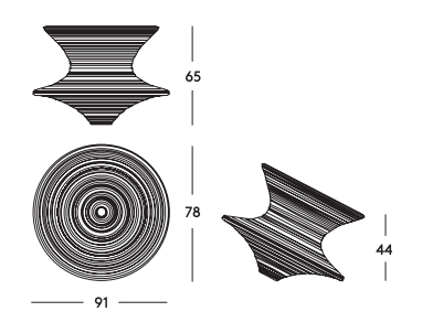
When designing moving objects, one has to keep in mind the momentum and forces that will be applied onto the object. With a chair that rocks and spins, it's essential to get the correct ratio between the base, the side rim and the seat rim, in order to have the chair functioning as it is supposed to. I used the basic dimensions provided with the original chair to model my design parametrically.
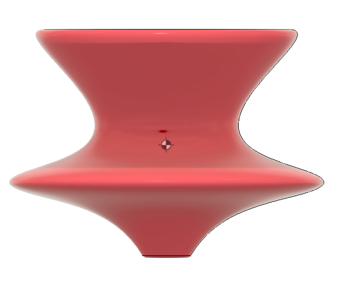
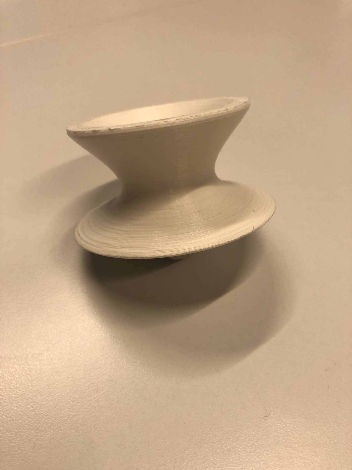
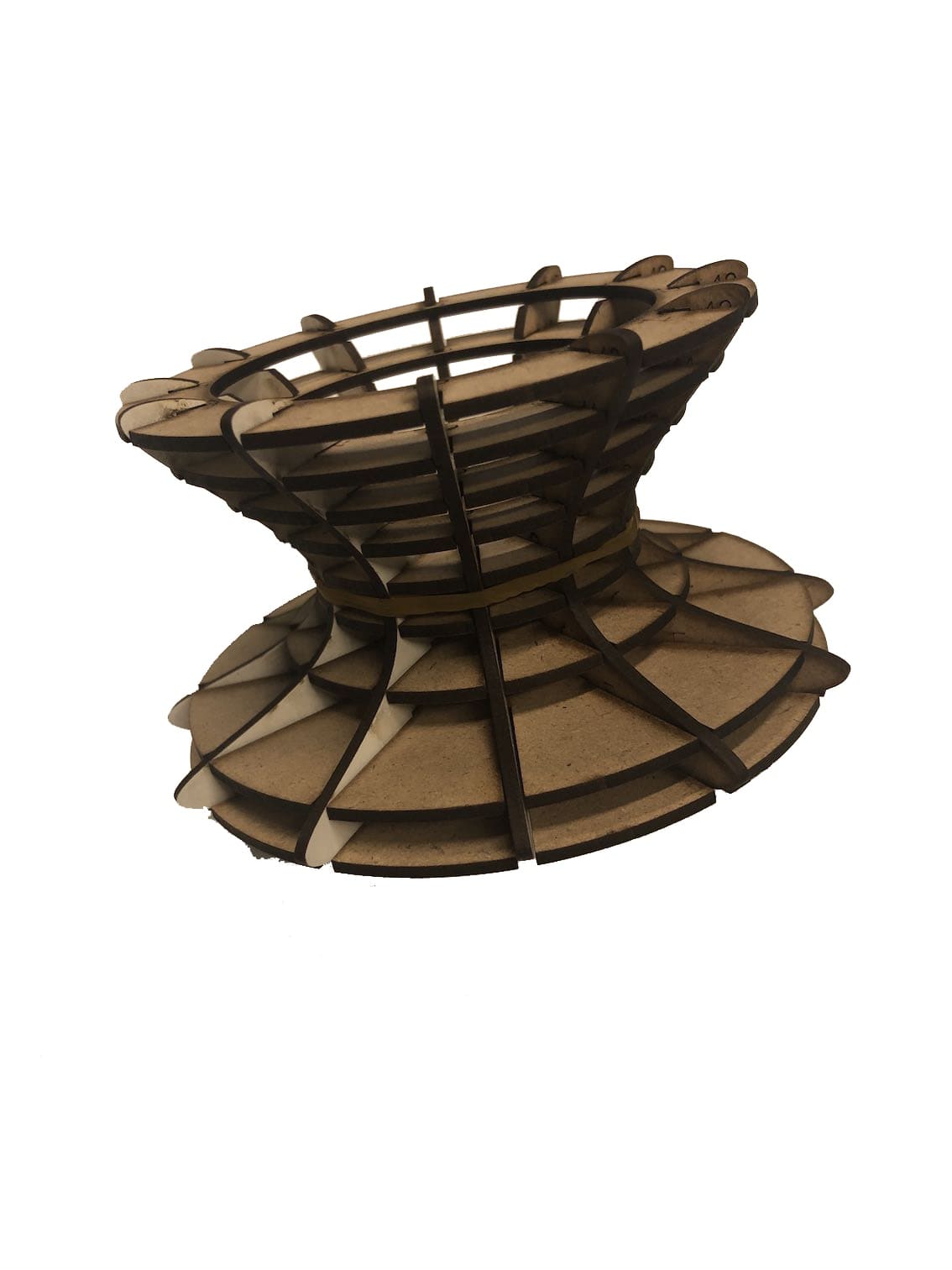
To test the basic design and ratios, I first found the center of gravity as I dont think any fancy simulations will provide any benefitial results. As seen below, the center of gravit is below the middle rim, which means it's stable enough standing alone. So I decided to take it a step further and produce a 3D-printed model to see how easily it would topple over with different directional forces applied to it. The model surprisingly robust and was extremely hard to topple over the side rim. I was now ready to move on to designing the parametrically sliced model.
Center of Gravity
3D printed part
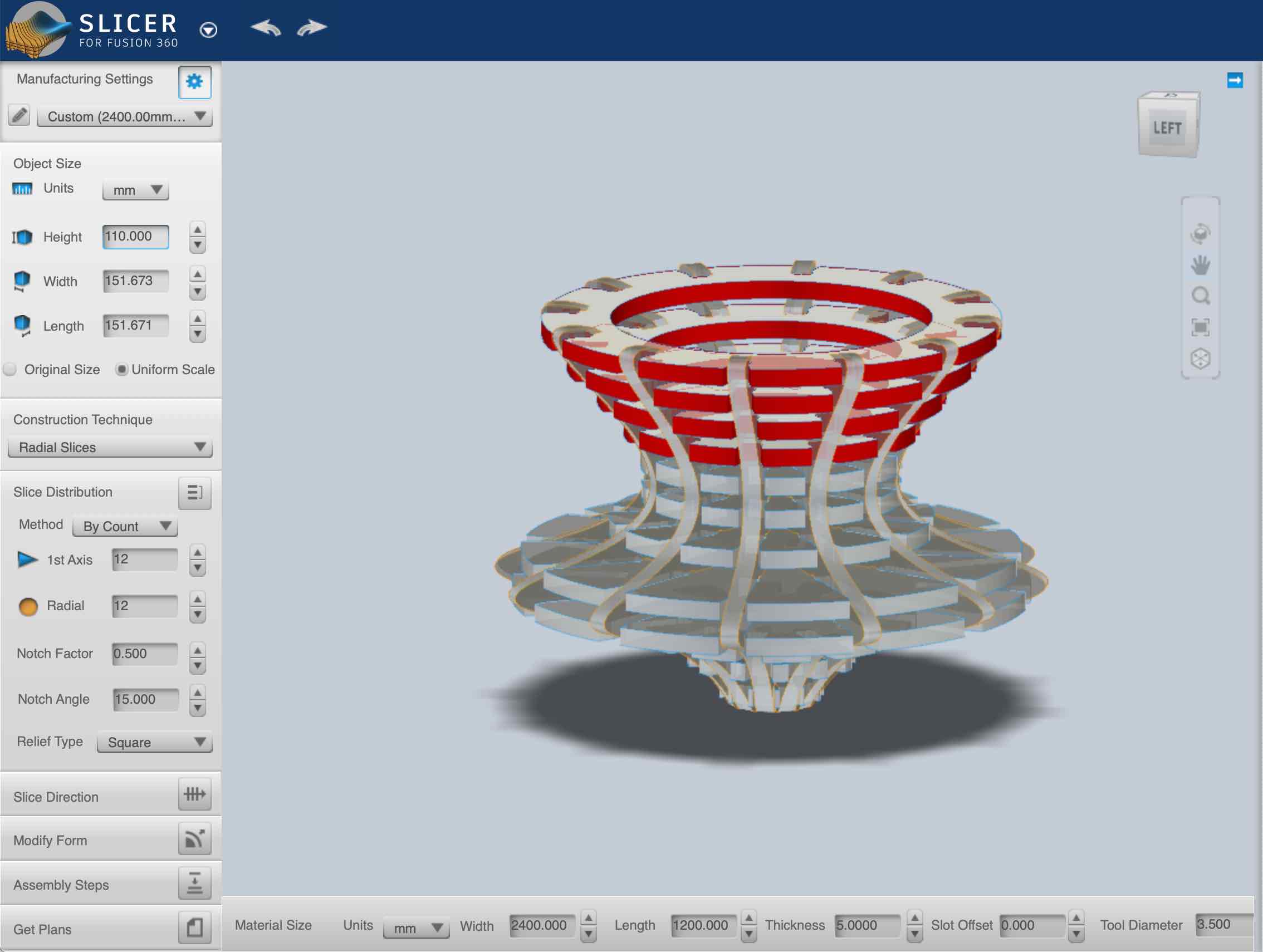
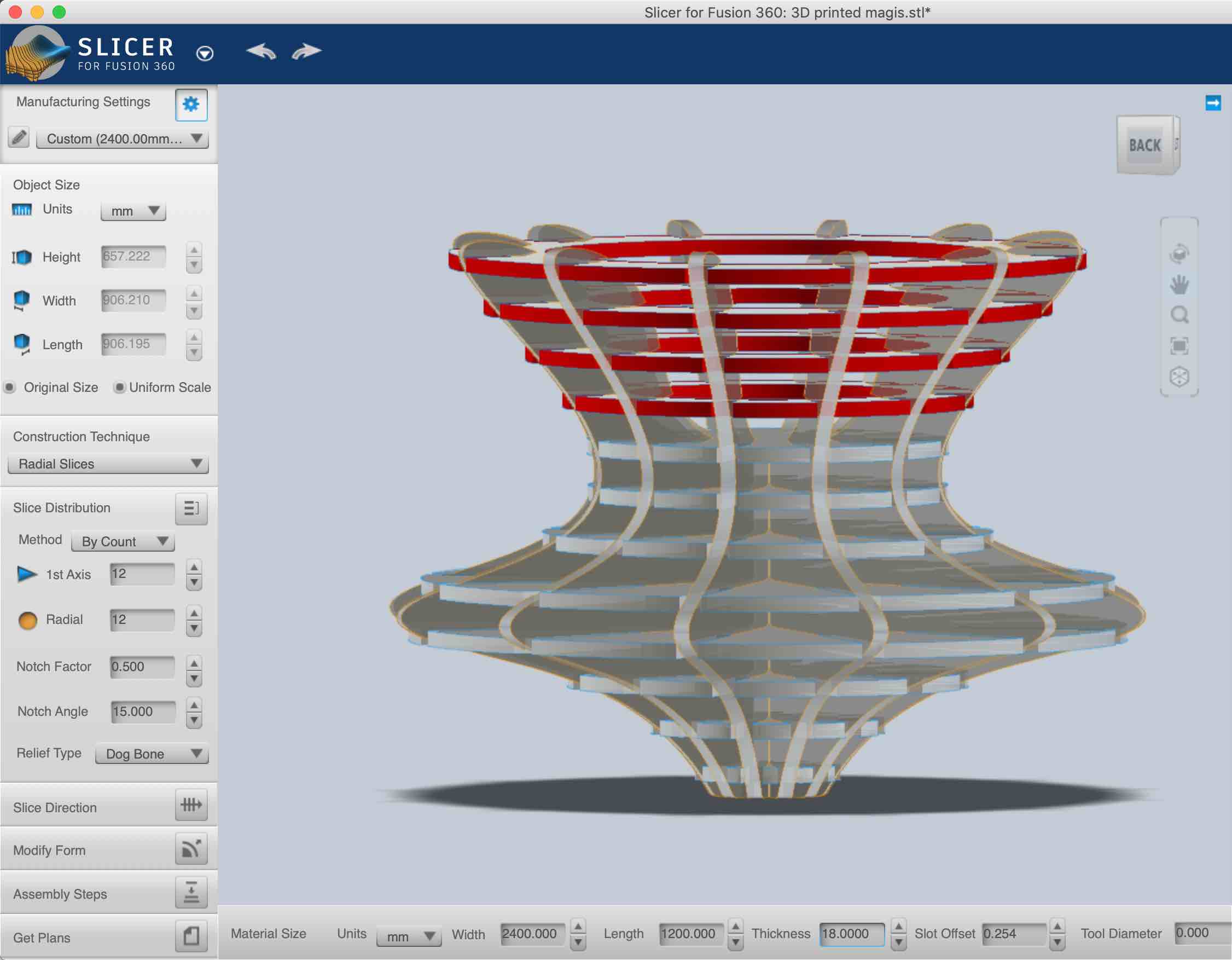
As mentioned in the overview, the spinning top model is going to be redesigned, since manufacturing it using a CNC will require a large ammount of material and a multi-axis CNC with 4 or more degrees of freedom, which also isn't available. To create a skeleton of the model, per say, I used Autodesk's Slicer for fusion, previously known as 123D.
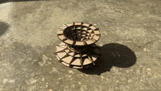
The program performs various types of model transformations and can slice it into layers, cross panels, radially, etc... Since I had used slicer during computer controlled cutting week, I was familiar with the interface and had only to tailor the settings for a shopbot machine rather than a laser cutter. Before doing that, I decided to test out a radially sliced version of my model and produce a 1:6 scaled down prototype using the laser cutter.
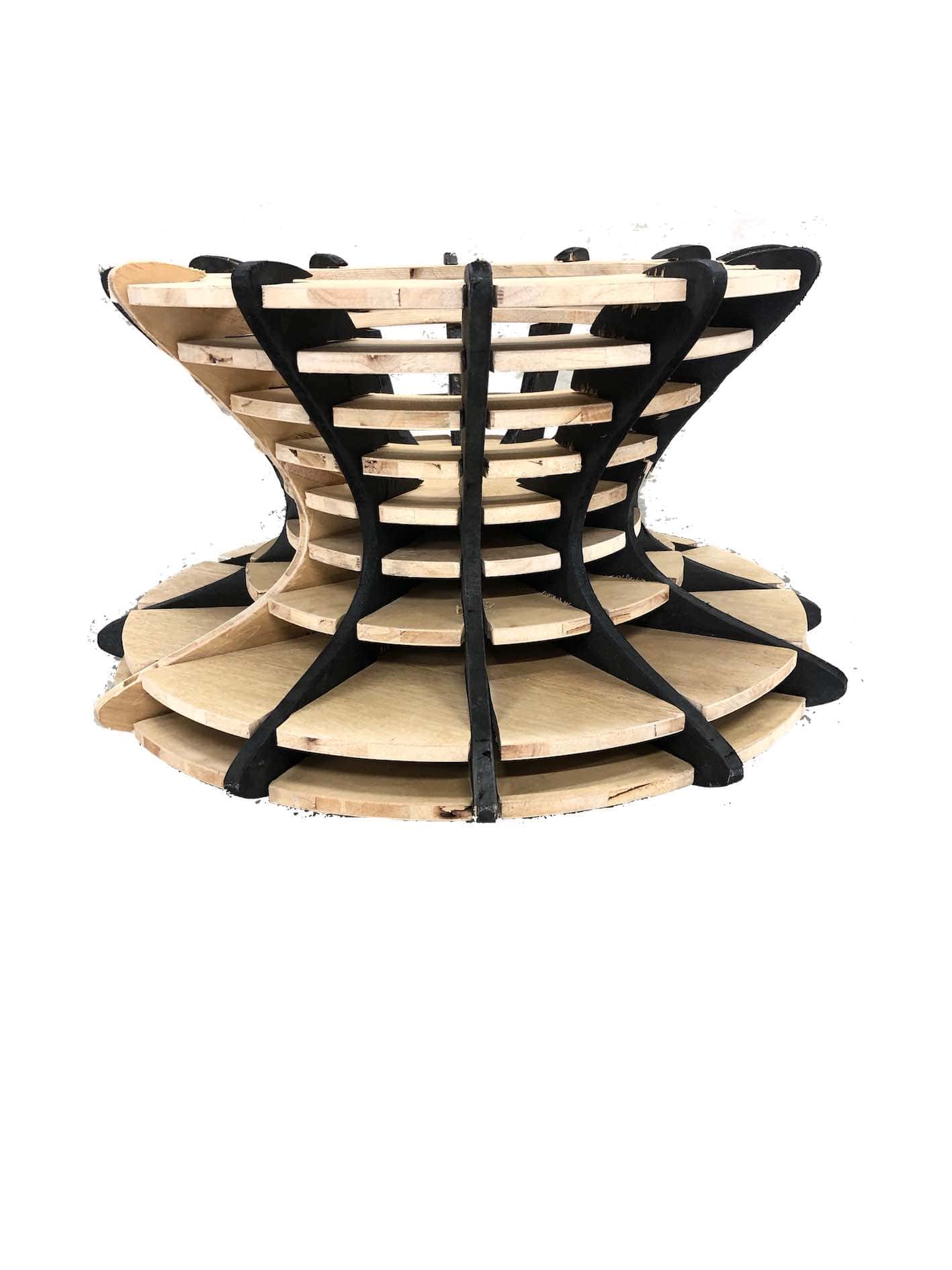
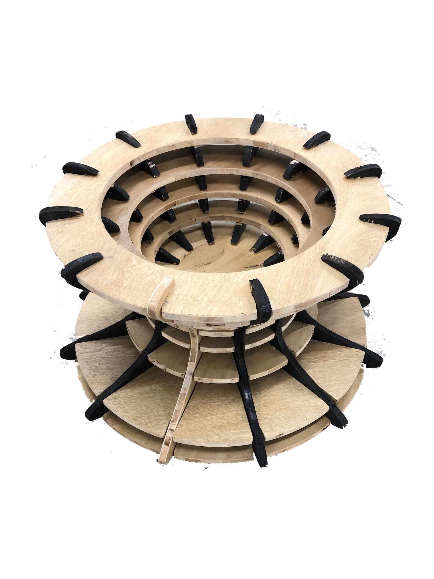
The pieces fit together well, but the kerf allowed slight wiggle room for the pieces at this size. Since there is only tolerance fit and no kerf with CNC cutting, this shouldn't be a problem in the larger scale model.
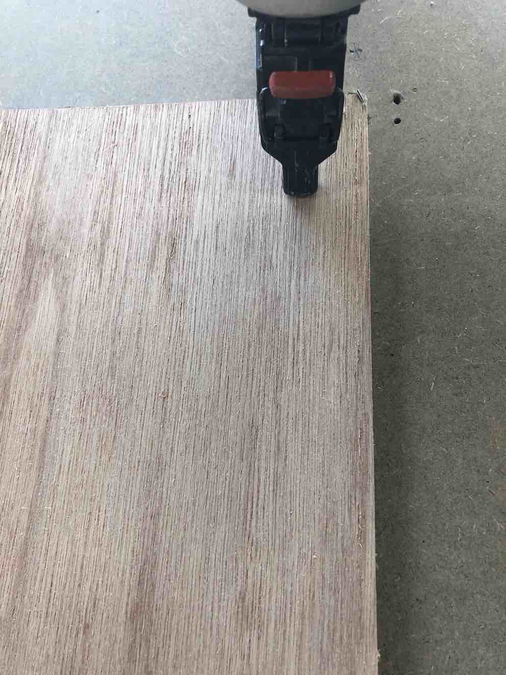
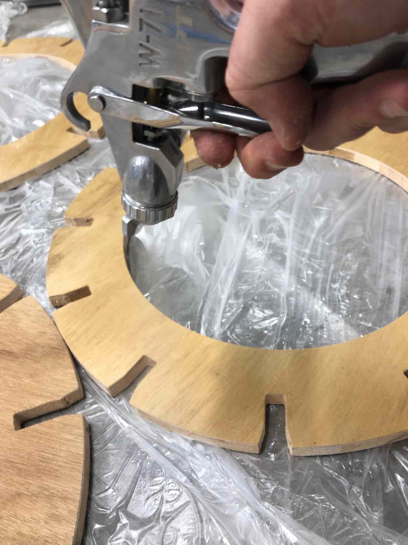
Before setting up the CAM for computer controlled machining of the pieces, I went back to slicer and setup the material settings required. I used 18mm, which I later realised should have been 185 to account for easier fit. I also added dogbones to the holes, since 2.5D CNC machining cannot achieve 90 degree sharp corners.
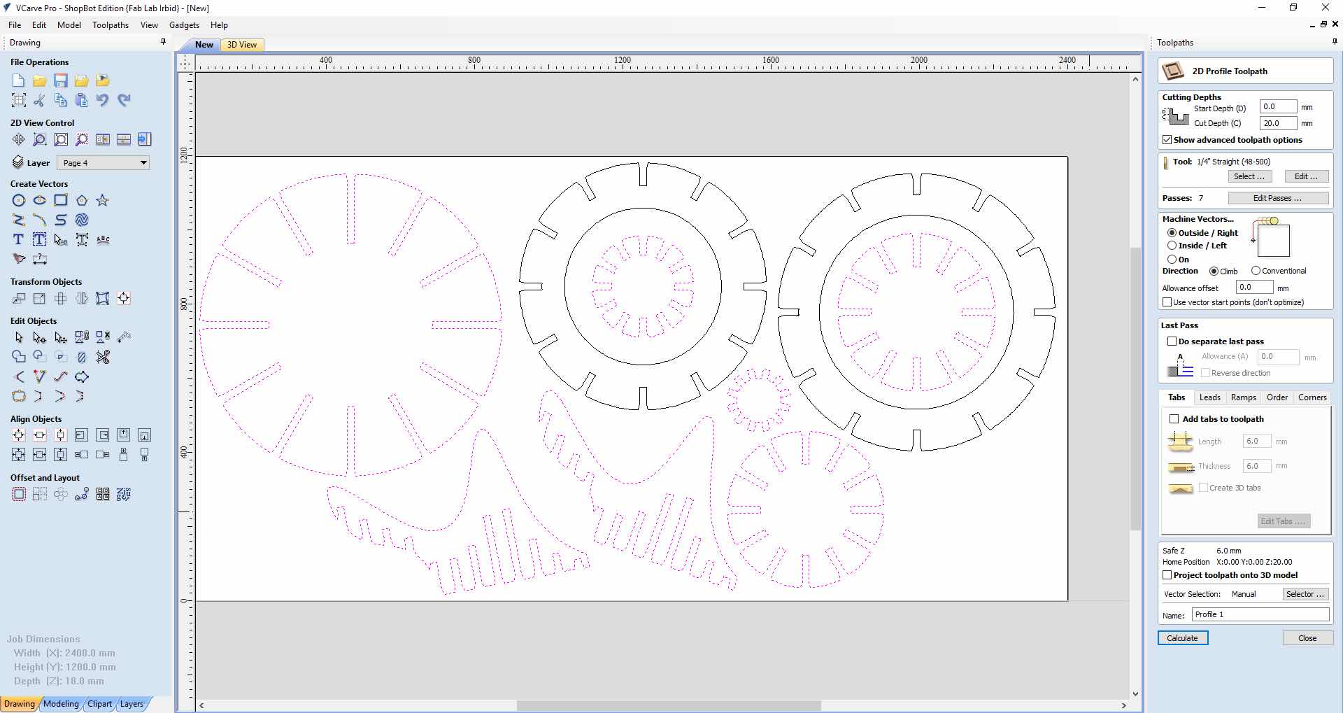
Once the model files were ready, I output a DXF which I imported into Shopbot's CAM workspace, Vcarve pro. I created the CAM toolpath for a 1/4 inch flat endmill. I set both the step down and step over to 50% of the endmills diameter, 0.125 inches. The step down and step over specify the degree of the finish, to a certain point, the small these values the better the finish. The spindle was set to 19000 RPM since it was relatively worn down. I then proceeded to creating the toolpath, starting with the inner paths which are any holes, or hollow areas and then setting up the outer cutting toolpath for the outer edges of the pieces. I oriented the pieces in a way to avoid material waste and produce as many pieces as I could per board. Due to the different sizes I was able to fit some pieces inside eachother, and therefore had to create a seperate toolpath for the outer pieces after the inner ones where cut out.
Inner toolpath
Cutout of inner pieces
Outer toolpath
In order to nest the pieces and organize them in the most efficient way, I resorted to the manual way, trying to fit parts in eachother and next to eachother with the minimum ammound of space in between. I was made aware by my global evaluator that this feature can be done automatically in fusion, but that was after I completed the cutting process.
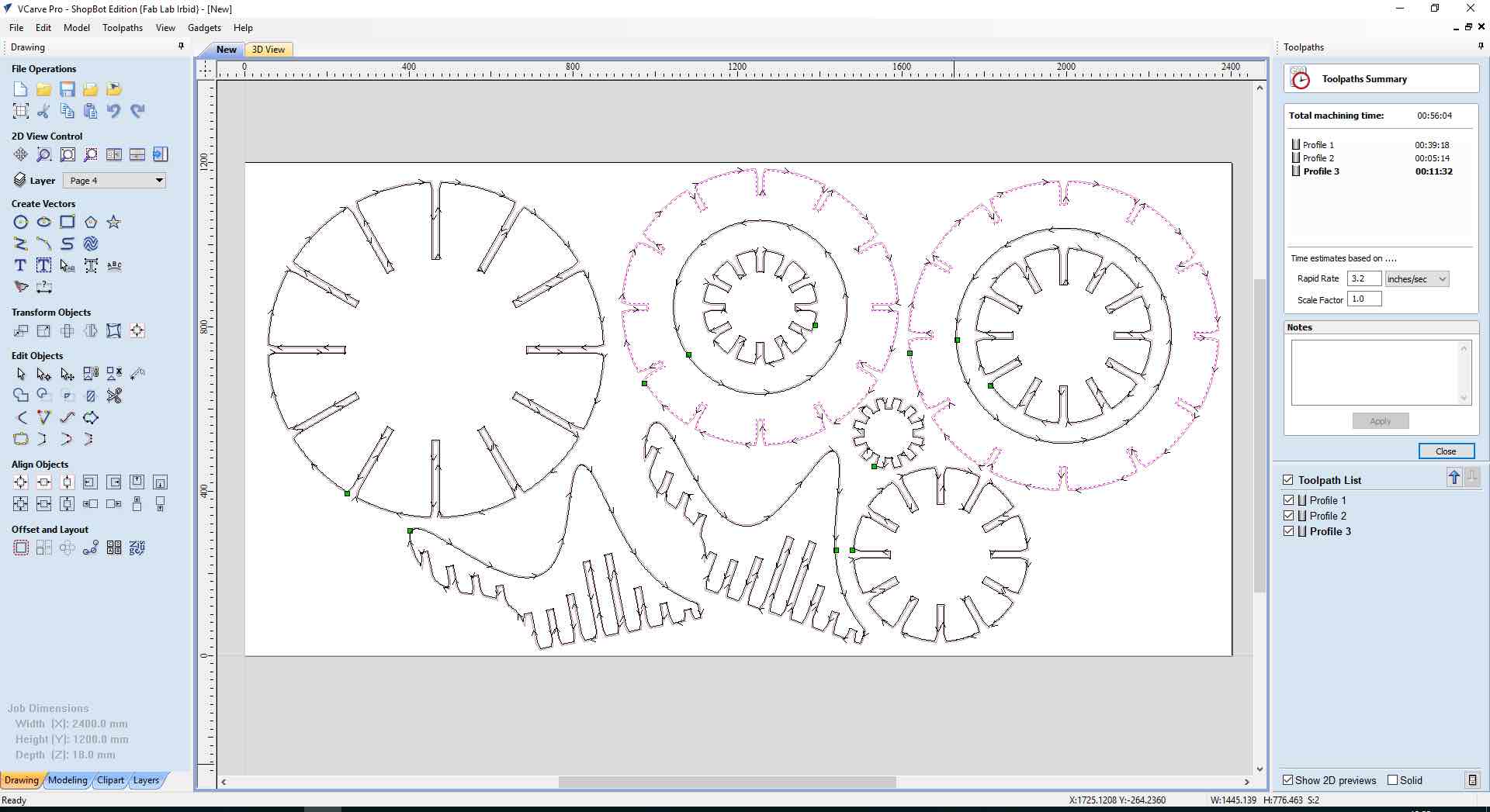
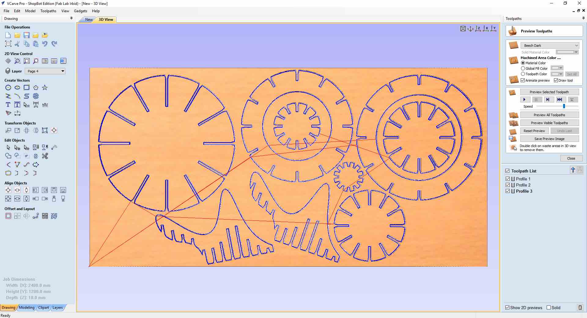
I then simulated the cutting paths to ensure everything worked as planned. The speed of simulation can be controlled using the slider at the bottom.
Once I was sure of the cutting toolpath and tool settings I exported the gcode using the button shown on the right. I also saved the Vcarve file incase I needed to go back and change some settings to output another gcode.
I then fixed the sheet of wood to the router's sacrificial layer using a nail gun. I avoided the use of screws to avoid the endmill from coliding with a screw, which is both dangerous and bad for the endmill.
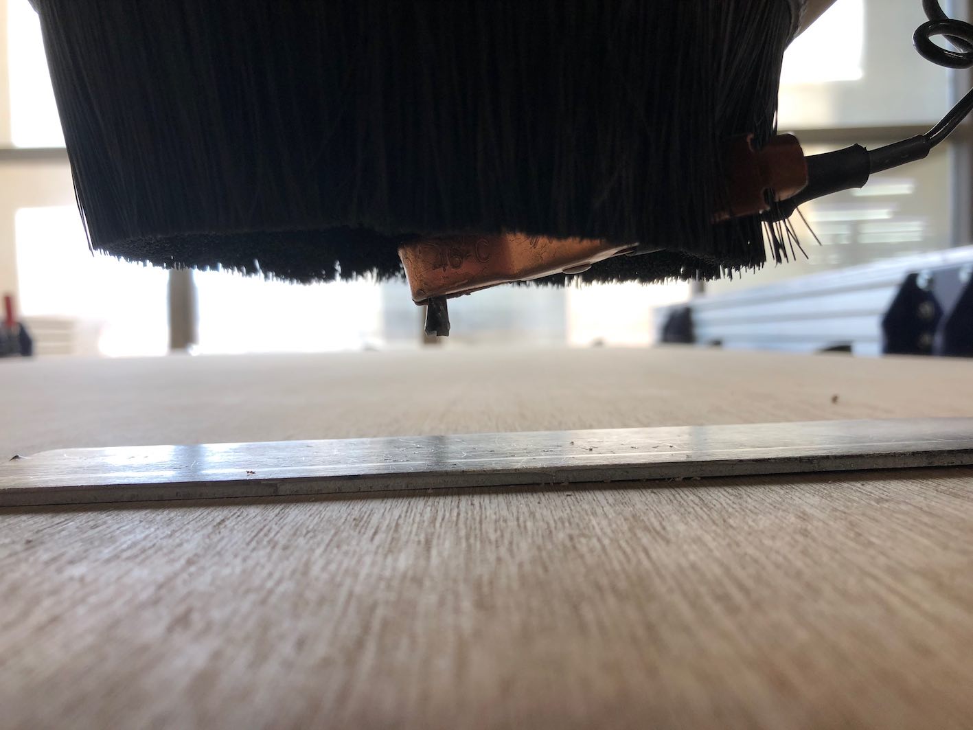
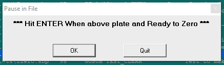
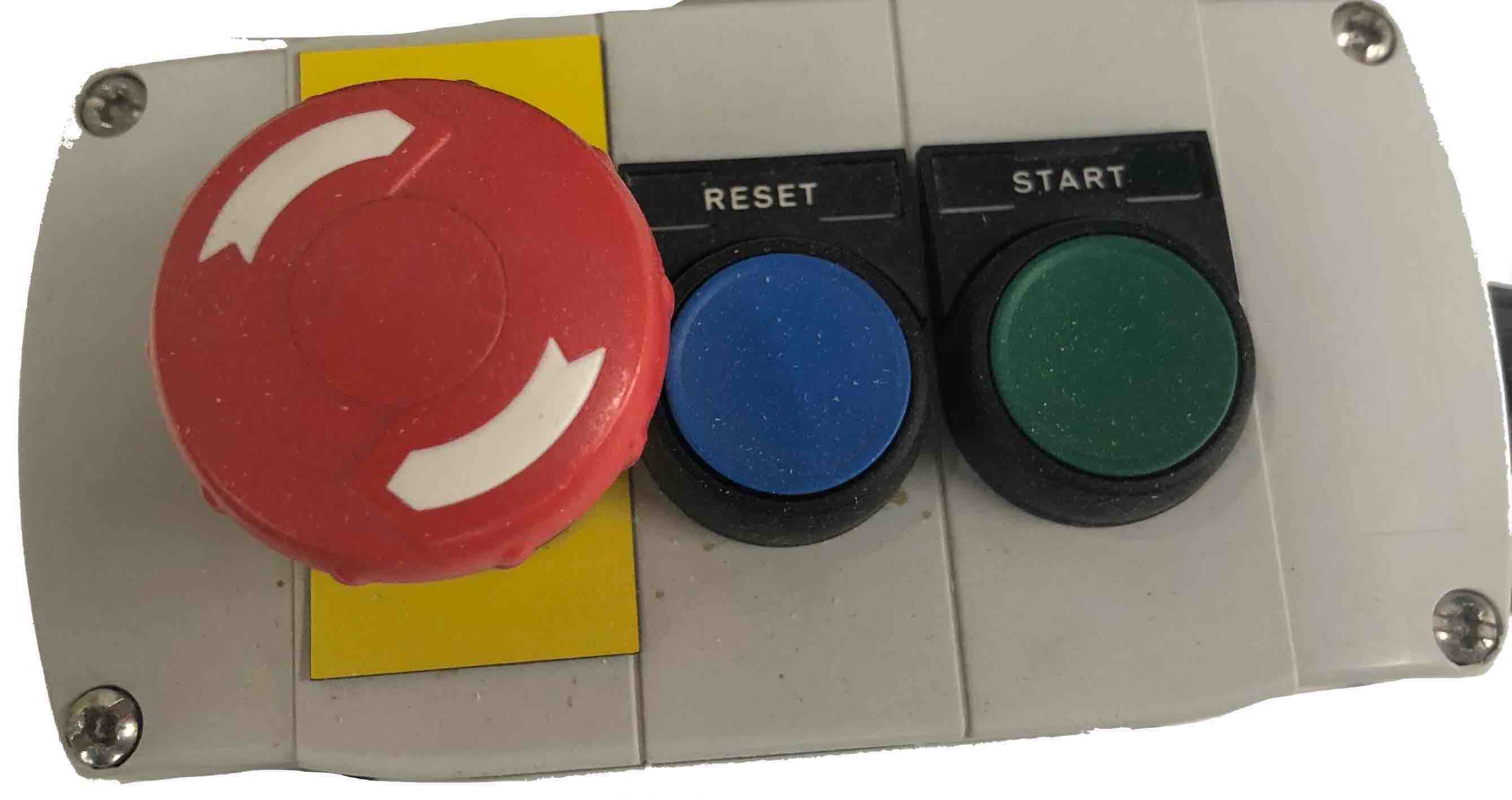
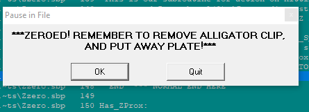
Now that the cutting GCode was ready to be output to the machine, I had to fix the board, place the metal plate right under the endmill and the copper clip on the endmill. Once all is ready, I clicked the zero axis button on the shopbot controller, then hit the green button to start the process, the machine decends twice until the endmill comes in contact with the metal plate. Once the process is done a message will come up reminding you to put away the alligator clip and plate. Note: the red button is used to emergency stop the machine whenever.
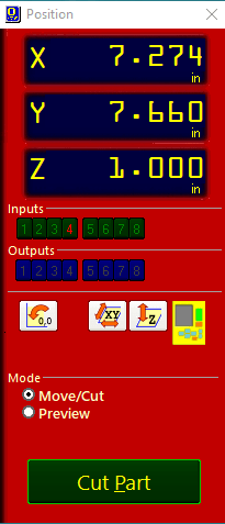
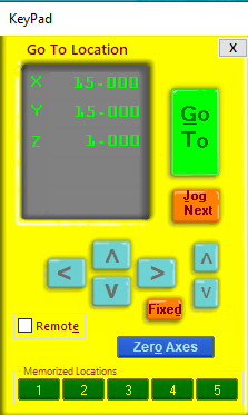
This is the main control panel for the shopbot it is used to start the job, open the movement control panel shown below, which is used to zero the axis.
Then the X and Y zeros where set by moving the endmill to the correct position, using the control interface. Afterwards set the desired position as the home.
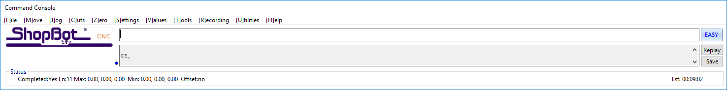
Then start the spindle warmup before starting the previously saved gcode file. Both these actions are done from the shopbot terminal shown to the right. The warmup routine is chosen from the Cut menu while the File is chosen from the file menu. Both are initiated from the start cut followed by the manual green button.
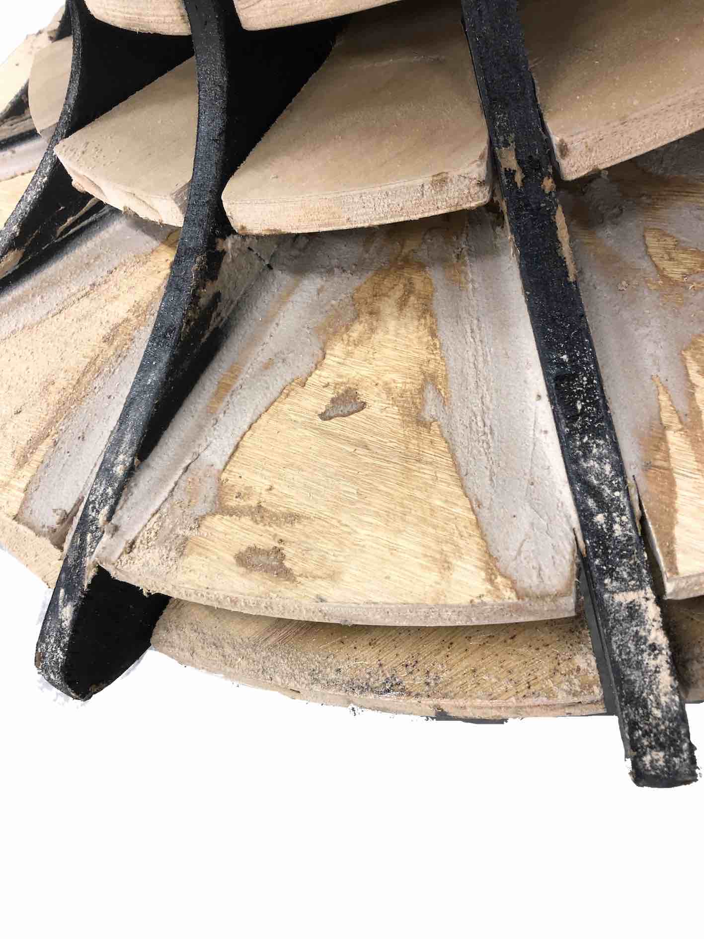
For post processing, I initially did some sanding to smoothen the edges and a file to remove any splints. I then moved on to spraying the cut pieces with laquer and paint. This was done by mixing 1 part laquer with 2 parts water (since it was water-based laquer). Once a milk consistency was acheived, I filled up the spray gun and from a 30 cm distance sprayed the pieces using a consistent panning movement. Unfortunately the pieces didn't fit as easily as I expected and it turns out I had to sand the sockets even more. I sanded a few millimeters out of every socket and then put the pieces together. Now that I had an assembled model, I decided to take the finishing to the next step and fill in all the holes and paint it all to cover up all the joints.
For the first step of the additional finishing I created my own filler by mixing together wood glue and sawdust until I achieved a paste consistency.
The finishing is still underway and since its additional to the requirement I will be following up the updates once it's done.
-min.png)