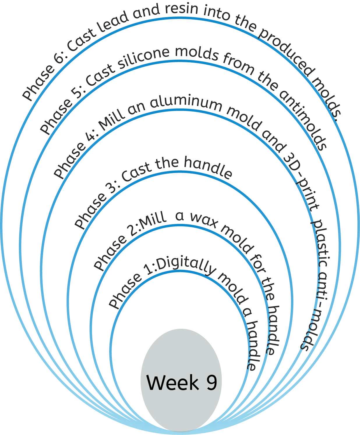
This week was focused on molding and casting. We had to experiment with three stage molding and casting. It was a very interesting week, allowing me to experiment with different materials and production techniques. My goal was to produce a multi-stage multi-material logo for my final project. But since the wax milling required some time, I was simulaneously working on producing handles for my final project using other techniques.
Making a mold and cast of an SLA print
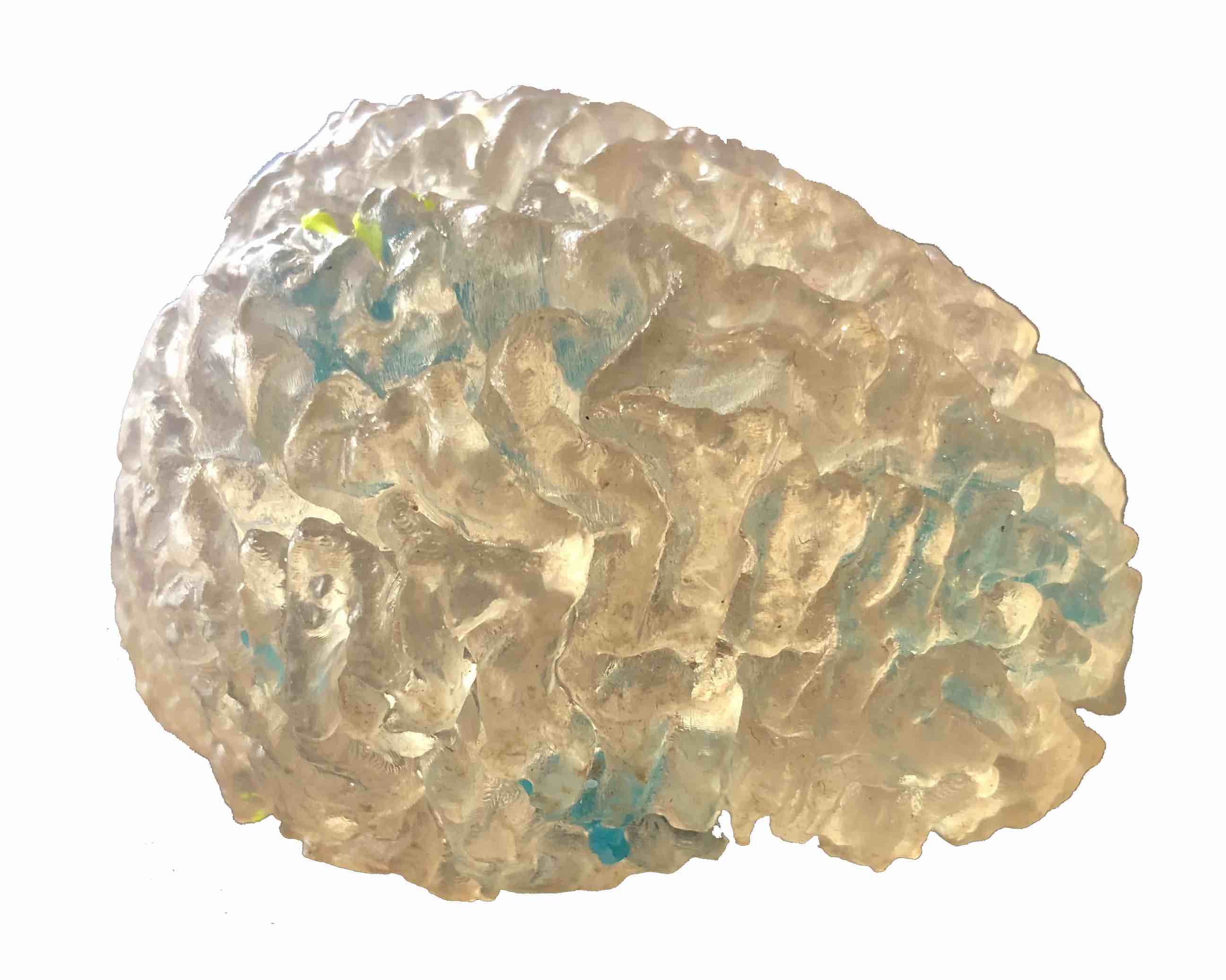
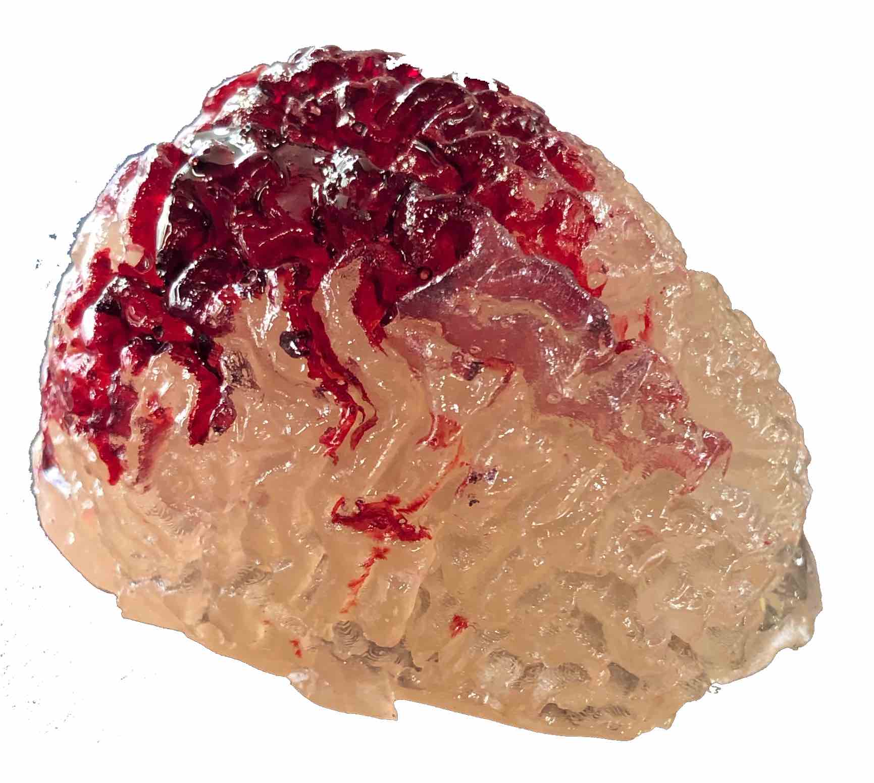
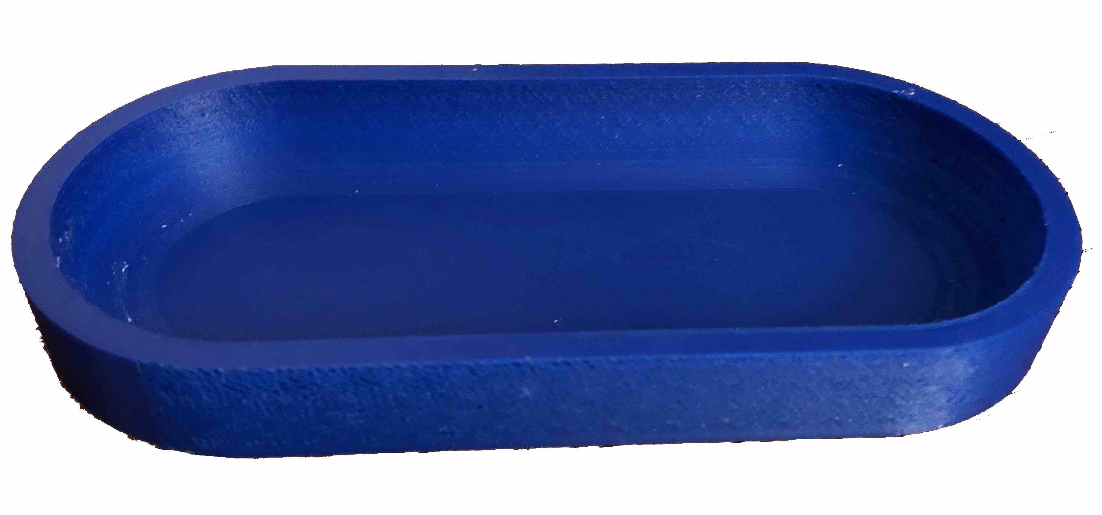
To first try out the colours and experiment before making the parts I wanted to casts, I used an SLA print of a brain and used it as a trial part for the colour of the molding and casting material. The reason why the colour of the molding material is important is because I will be using it as casting material instead for the handle grips of my final project.
To create the mold I found an empty plastic box with a size large enough to encapsulate the brain model but small enough so as not to waste material. I used double-faced tape to stick the model to the bottom of the box. Afterwards, I poured a Smooth-on's Moldstar 30, which comes in a blue color. Before mixing parts A and B of the molding material, I added some yellow pigment to acheive a turqoise colour.
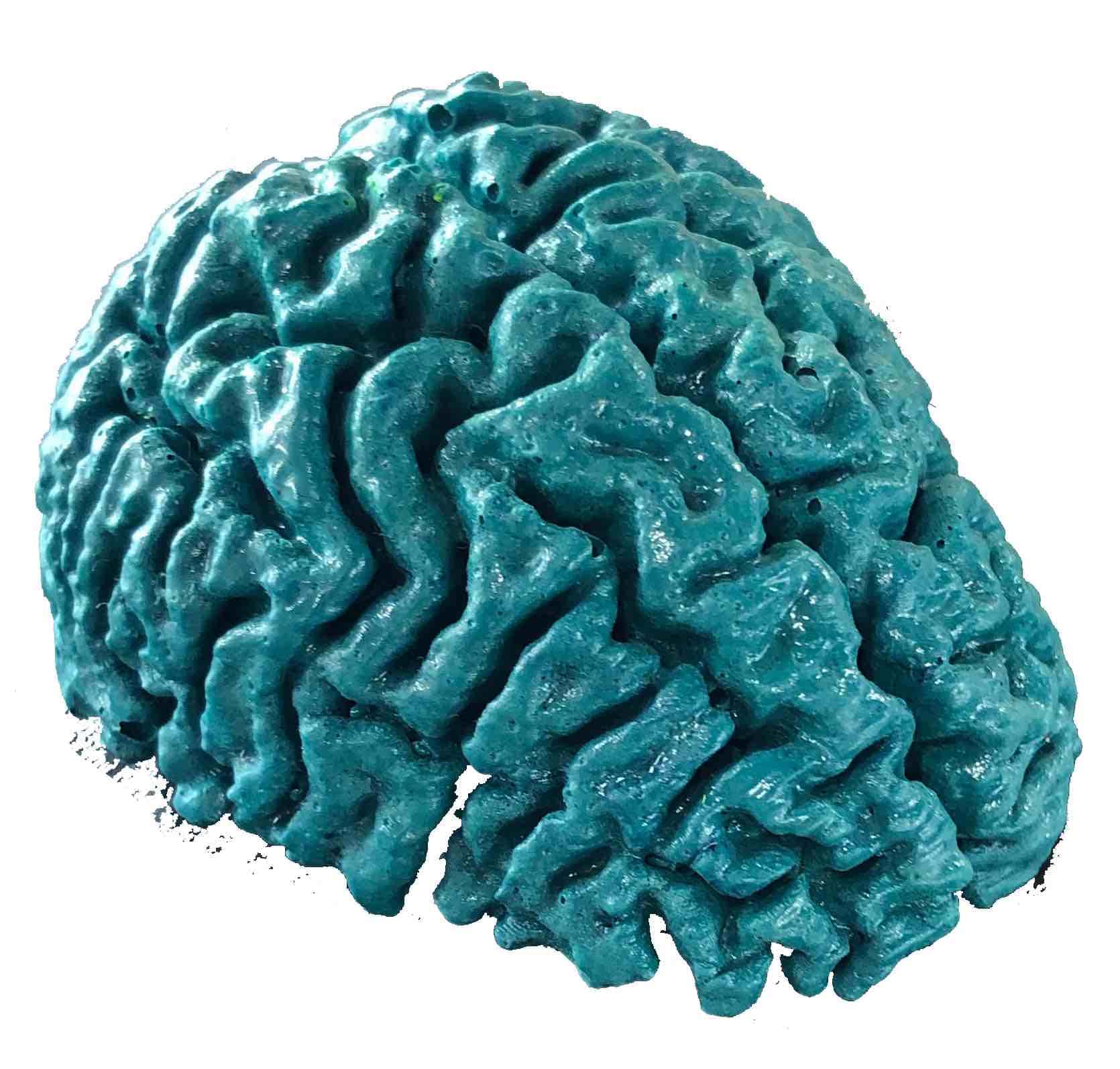
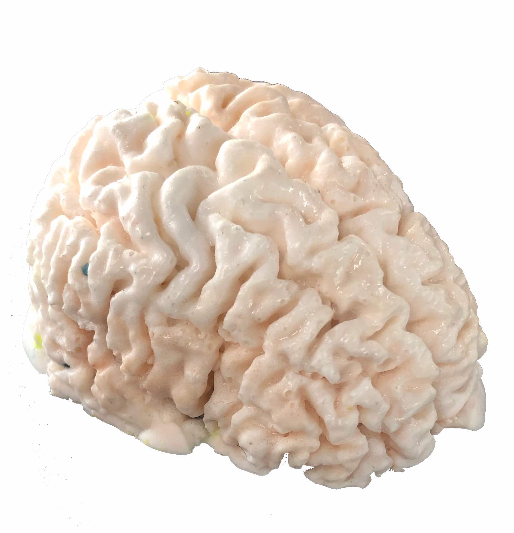
Then the mold was then used to cast remaining casting material and produce very cool looking brain models. The first was cast with the remainder of the liquid plastic used for the letters, the second with the liquid plastic used for the back panel and the third using the resin from the capsule with two drops of red pigment placed in the mold before casting to produce a blood effect.
Turqoise Liquid Plastic
Flesh Colored Liquid Plastic
Flesh colored resin with unmixed red pigment
Digital molding and designing the handle
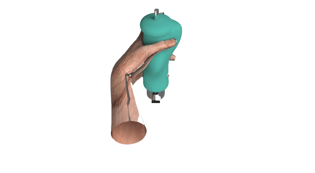
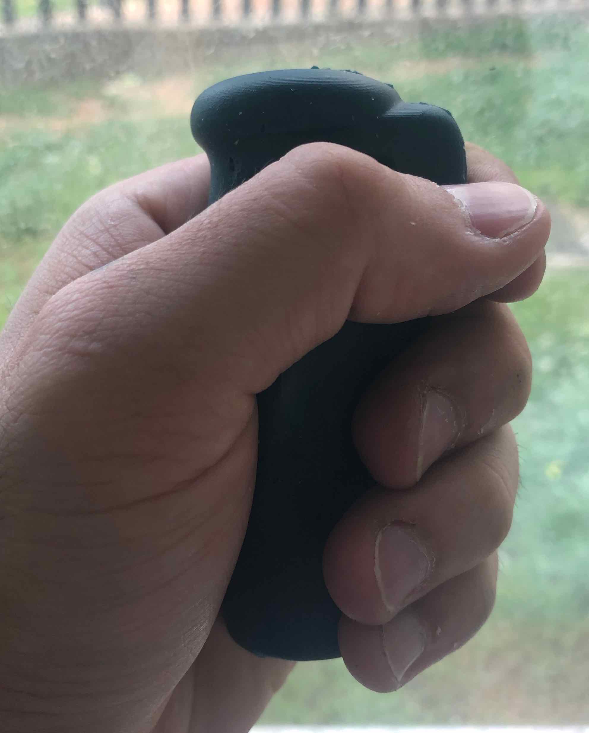
To design the handles for my final project, I opted to model a grip that would take into consideration arthritis patients. The ergonomic design was achieved by referring to this study on ergonomic grips for hammer as well as sculpting the surface according to an imported model of a half clenched hand.
Then I created a box around the model equal to two blocks of wax and subtracted the model from the box. I also created an extrusion which extends to the aluminum extrusion in the middle. The aluminum extrusion is represented by a 3D printed piece of plastic that has two extrusions at the bottom and a thin pole extruded from the top to ensure correct placement within the molds once the silicone is cast.
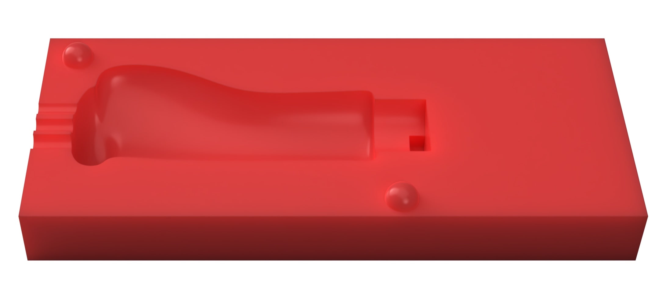
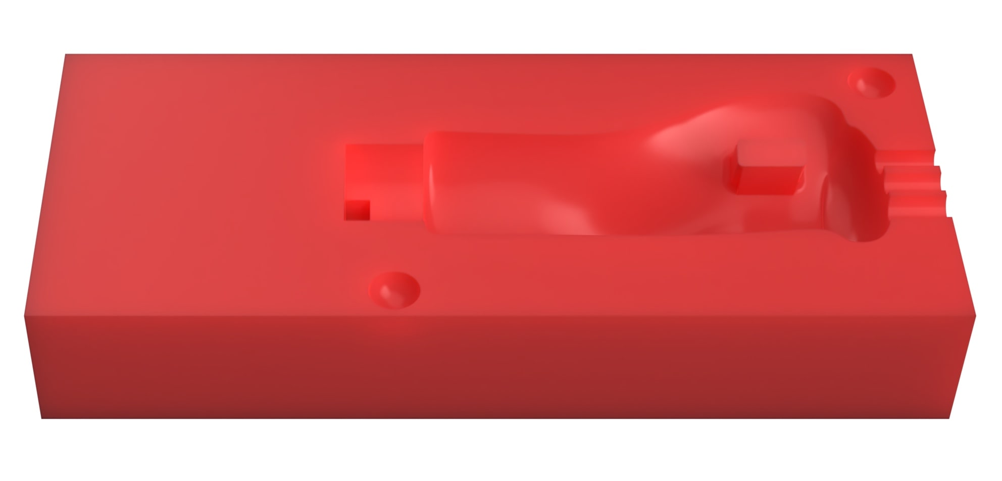
Top mold
Bottom mold
Aluminium shaft
Milling the handle molds
I milled each side using a different CAM program for the sake of learning and comparing between both workflows. For the first mold I used Modela and for the second I used Roland's SRP player. In both workflows, I used a 1/8 inch flat endmill for the roughing process and a 1/16 ballnose endmill for the finishing process. In both cases I zeroed the Z-axis by placing 1mm paper under the mill and slowly wend down. Once there was resistance when moving the paper, I took the Z-axis 1mm downwards and set the home. As for the X and Y axis, I drew an X from the corners of the wax block and centered the endmill at the cross-section of both lines.
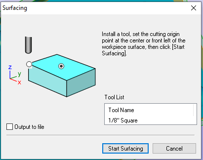
For the SRP player workflow, I initially started by sending a surfacing job. This was simply done by selecting surfacing from the tools menu. I input the dimensions of the block then in the next screen of the wizard selected the XY home in the middle.
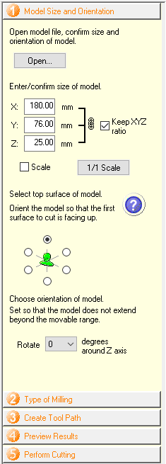
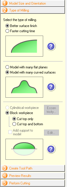
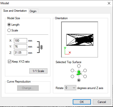
Before setting up the toolpaths, I must first import the model by locating it from the open button. Afterwards setting the dimensions of the wax block, orientation of the model and XY home position. Then the next step is to specify the type of milling and edges in the model. As is obvious, this program is quite automated and doesn't allow much personalization at first. The next step before simulation would be creating the toolpath.
Size and orientation
Milling specification
Toolpath creation
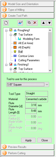
Although the toolpath is automatically created, one has the option to go through the edit menu and change certain parameters. As seen in the screenshot on the right, the roughing and finishing toolpaths are shown seperately with the parameters and properties of each. In my case, I changed the tools to the 1/8 flat and 1/16 ballnose. If anything was changed, remember to create the toolpath once again.
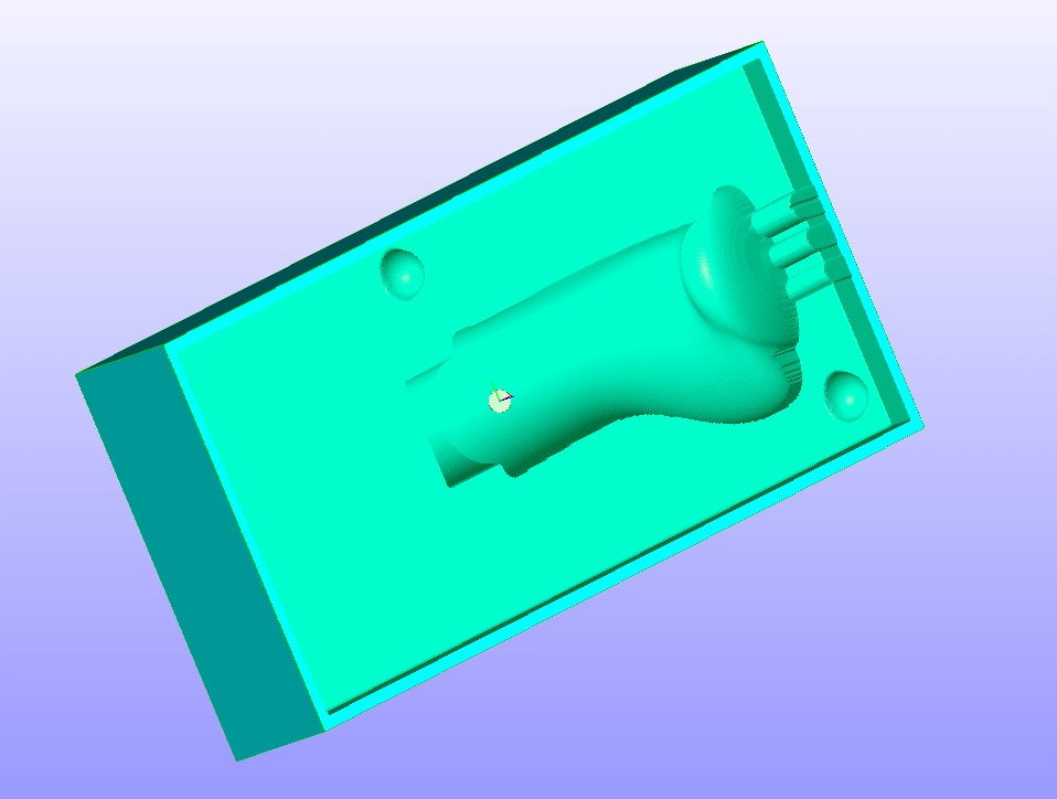
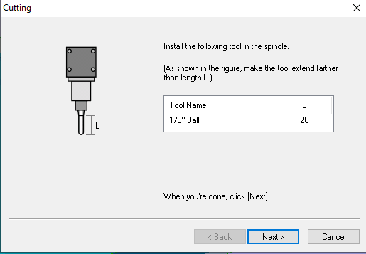
Once all the settings were entered and the toolpath created, I simulated the milling job and inspected the resulting model before going ahead with the actual job. A window will appear once a toolpath is complete to instruct you to change the tool, if required.
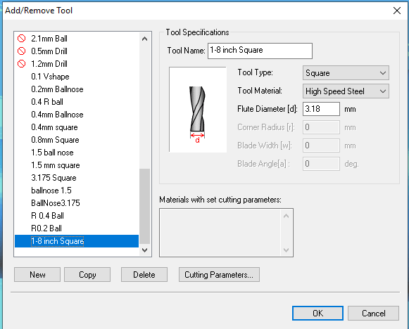
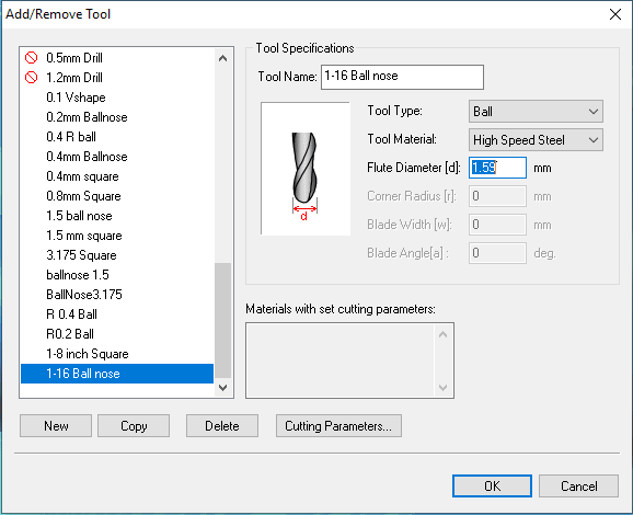
For Modela, I imported the model and input the correct size and orientation in the pop-up window that appears. Then I had to introduce the tools I will be using as they weren't available available in the tool library. Luckily, this was easy as after inputing the flute diameter, Modela can automatically generate suitable cutting parameters.
Import model window
1/8 flat tool
1/16 flat tool
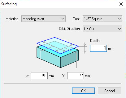
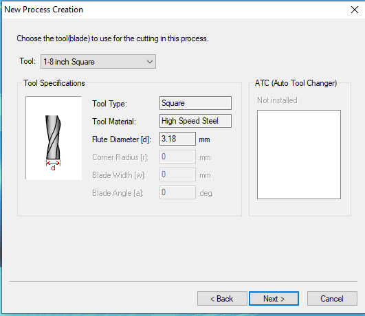
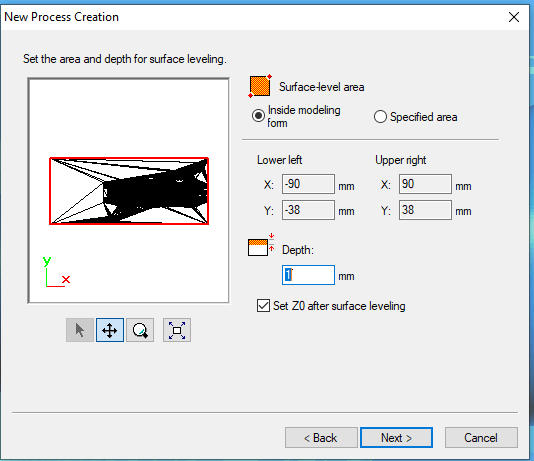
As opposed to SRP player's user-friendly path creation, modela requires the creation of each path seperately. This means increased control over the job and how the model is milled. The first toolpath would be the surfacing toolpath, so after creating a new toolpath, I was guided through a wizard. I selected surfacing, then selected the tool I will be using, then specified the paramaters and depth of the surface leveling, 1mm in this case.
Toolpath creation
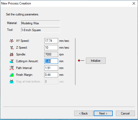
Tool selection
Surfacing depth
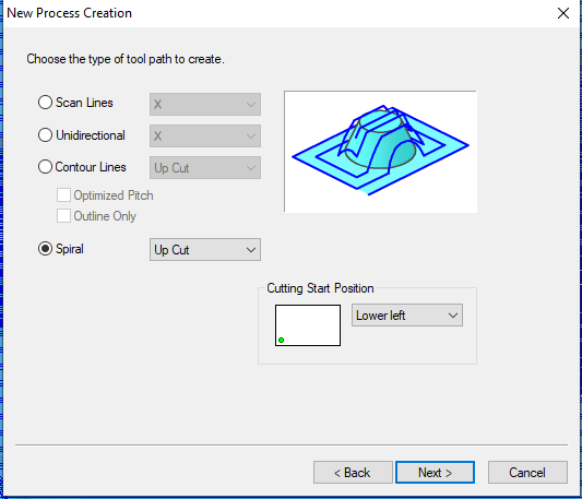
For the roughing and finishing jobs, the wizard is pretty much the same, however the settings differ. I left in 0.44mm when roughing, to be removed in the finishing jobe. Also to achieve a better finish for the curved surfaces in 3D, I chose the spiral upcut toolpath.
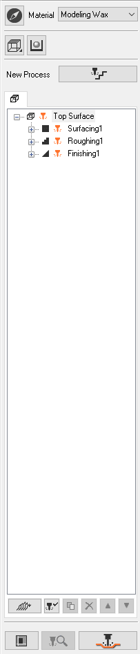
Once all toolpaths were created, they can all be viewed and edited from the window on the right. The next step after checking the toolpath parameters is to simulate the model CAM and then output the file. Note: This is also the side window from which new toolpaths are created and the model is output.
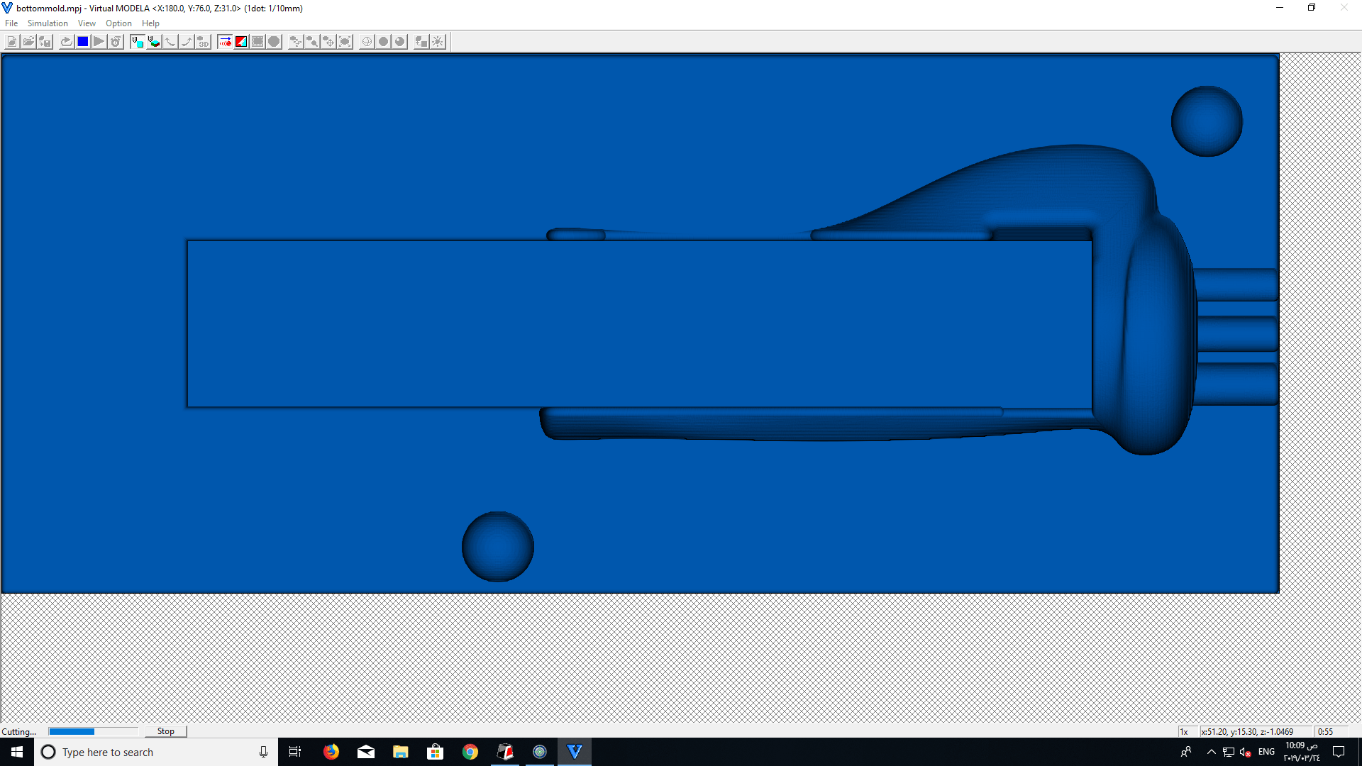
I ran the simulation and the model shown on the left looked like everything was okay and ready to be output to the milling machine.
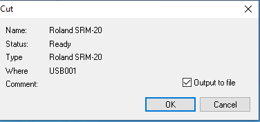
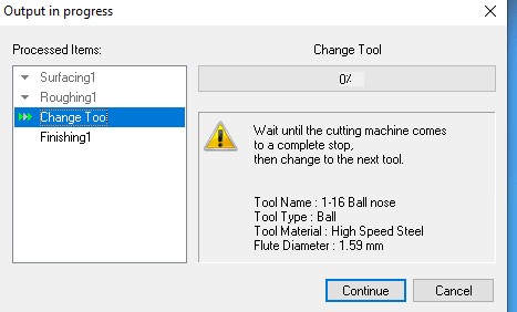
To output the file, choose the SRM-20. The progress window will indicate the progress of the job and instruct you to change the tool once a tool change is required.
Output to machine
Change tool (progress window)
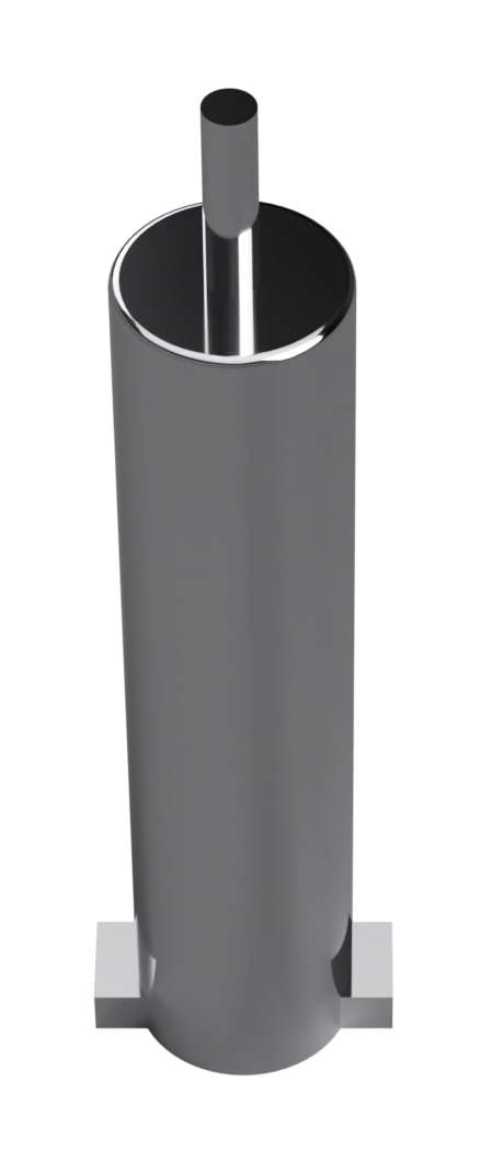
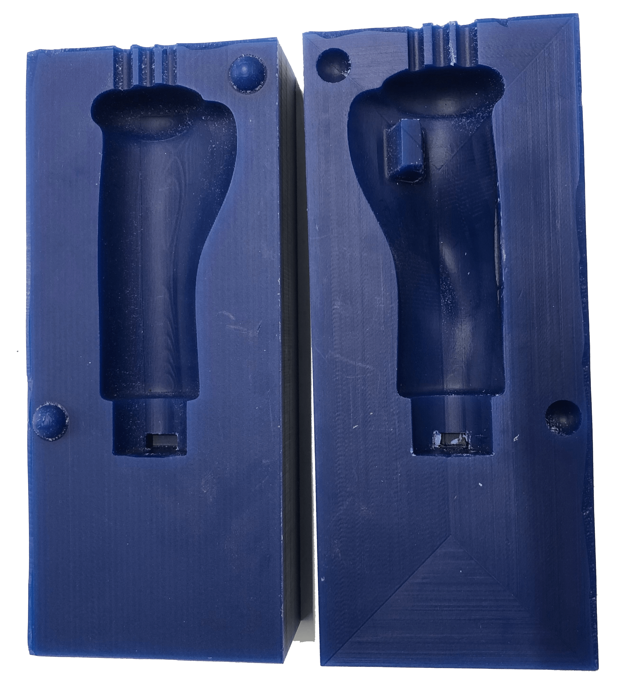
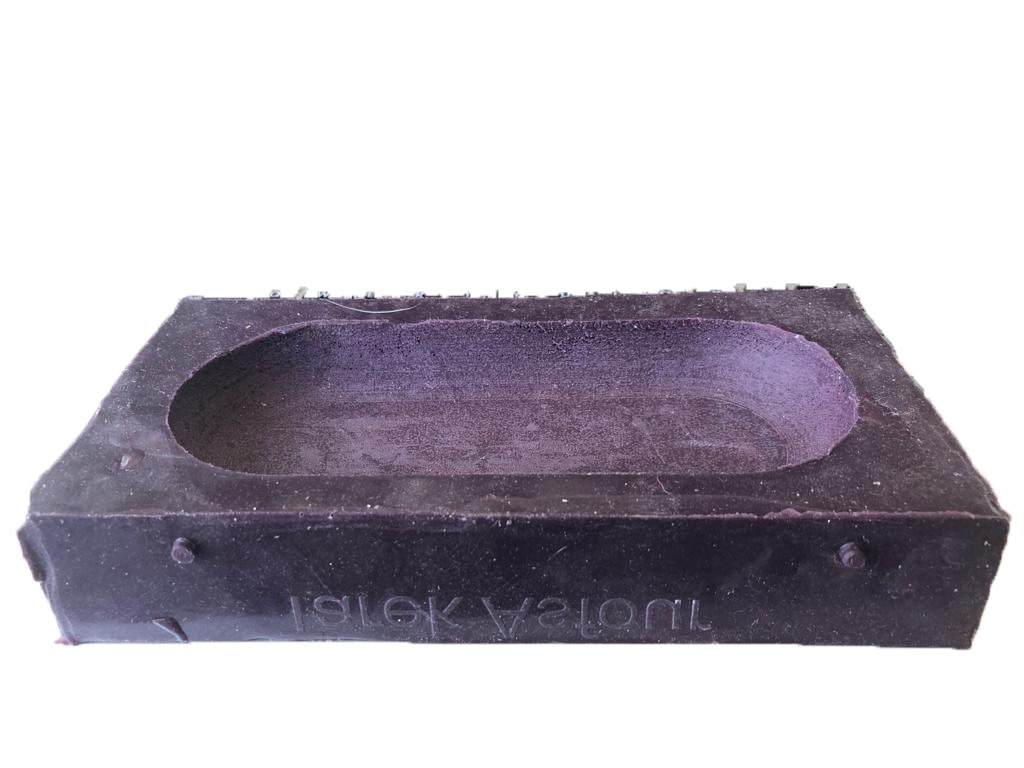
Below is a picture of the resulting wax molds.
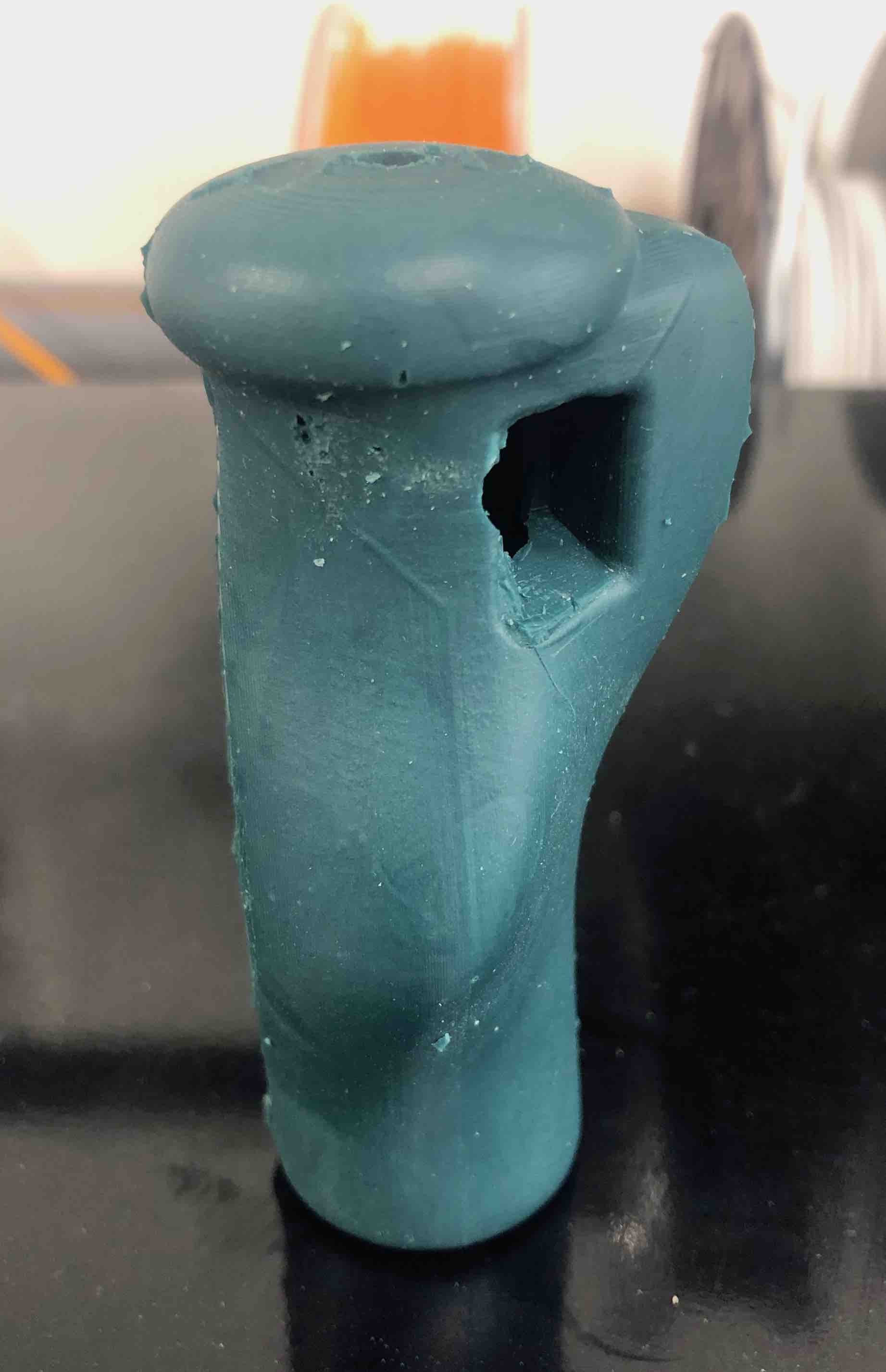
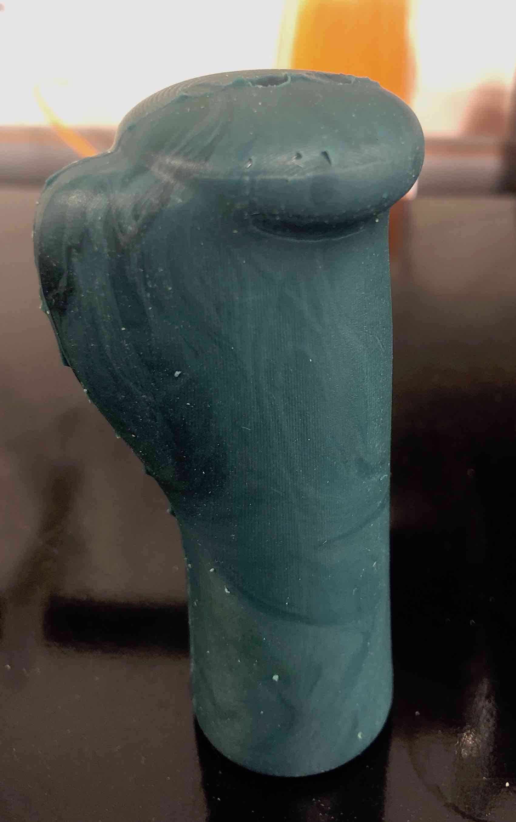
Casting the handle
Before mixing the MoldStar 30 silicon elastomer material, I did some research and refered to the , in order to check the pot time and cure time for the material, in addition to the mixing volumes and preferred temperature. So with a 45 minute pot life and a 6 hour curing time, I mixed together a volume of 1:1 of A and B, and poured it into the milled wax molds. I then pressed the molds against eachother and sealed them flush using one-handed bar clamps. 6 hours later, I pulled the molds apart and removed the model. Finally, I removed the excess silicon at the seam line using a box cutter. The following images and video show the complete process.
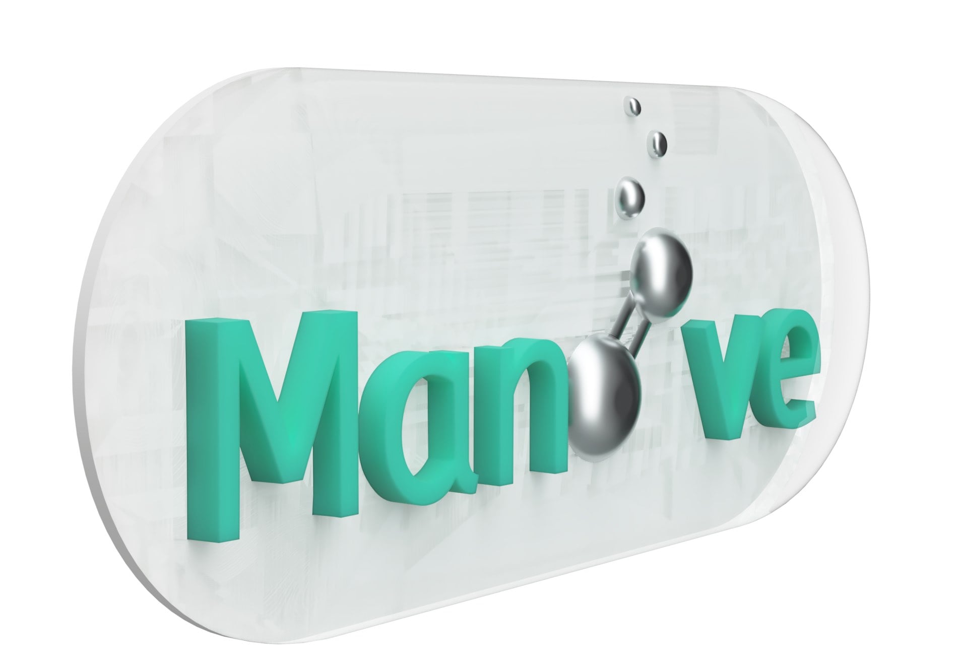
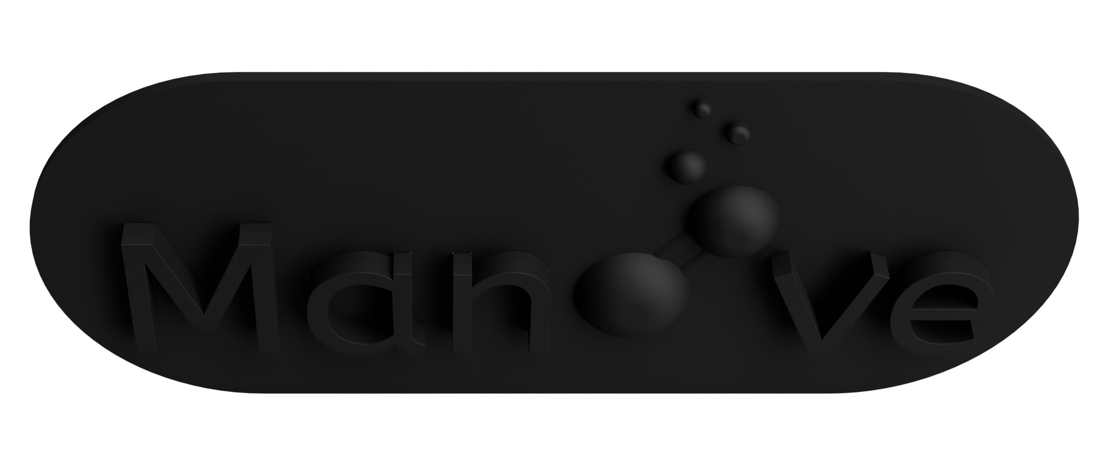
Designing the digital logo designs
The first step in manufacturing the logo was designing the logo itself in 3d including the negative molds that will be fabricated in order to cast into them. For the logo itself, I simply extruded the letters out and made the O's and bubbles into half spheres.
The next step was to design a 3D printed version of the logo including the back piece to be able make a mold in which the letters and bubbles would be set in place and connected to the back panel.
Then I designed a negative of the transparent capsule shape that will encaspsulate the logo from the front.
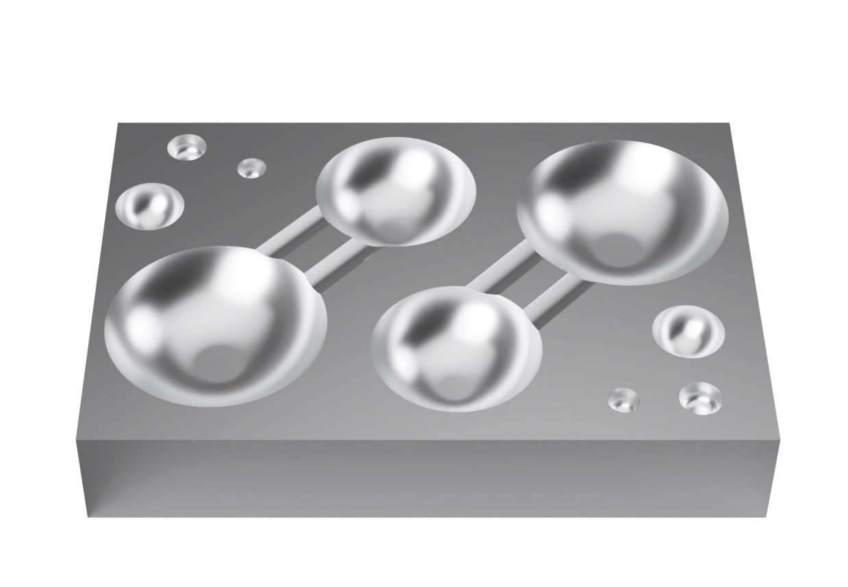
Finally, I created two copies of the bubbles and arranged them side by side in an efficient manner. Afterwhich, I created a negative of the model. This was the lead mold that will be milled out of aluminum using the tormach 1100.
Milling the metal mold
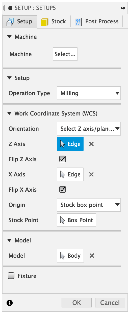
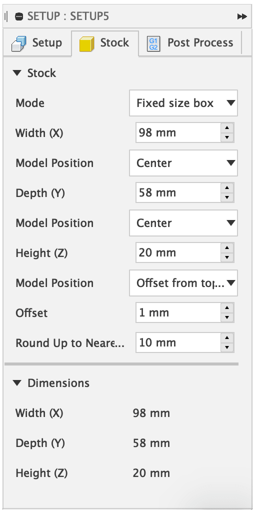
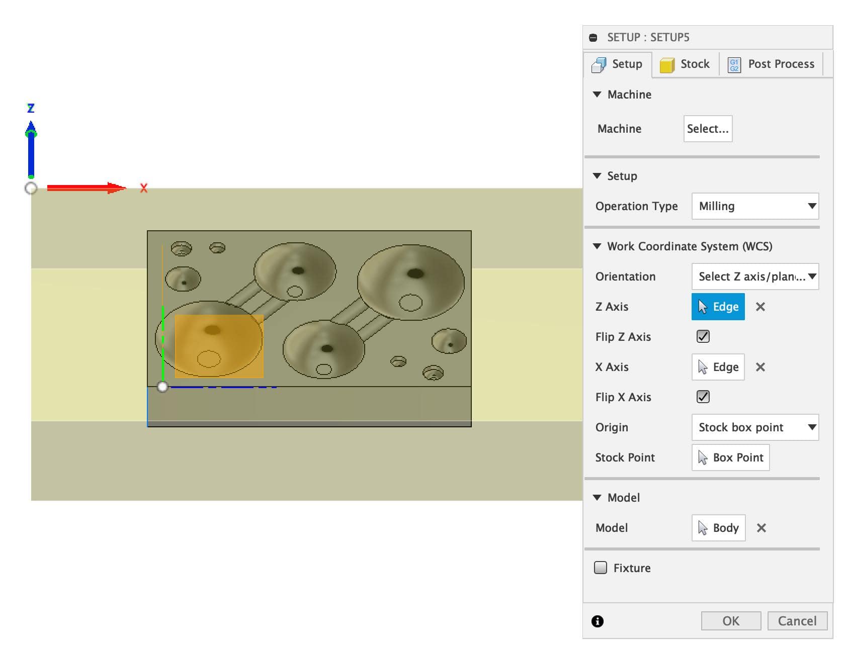
This was my first time using fusion360 CAM for practical application. Therefore, it took sometime for me to understand each setting and choose the correct technique/tool to simulate a CAM job and produce a part of the correct specifications. The first step was to measure the aluminium block available and input the dimensions of the block. Then I had to specify the origin point in reference to the job.
Job setup
Stock setup
Origin point setup
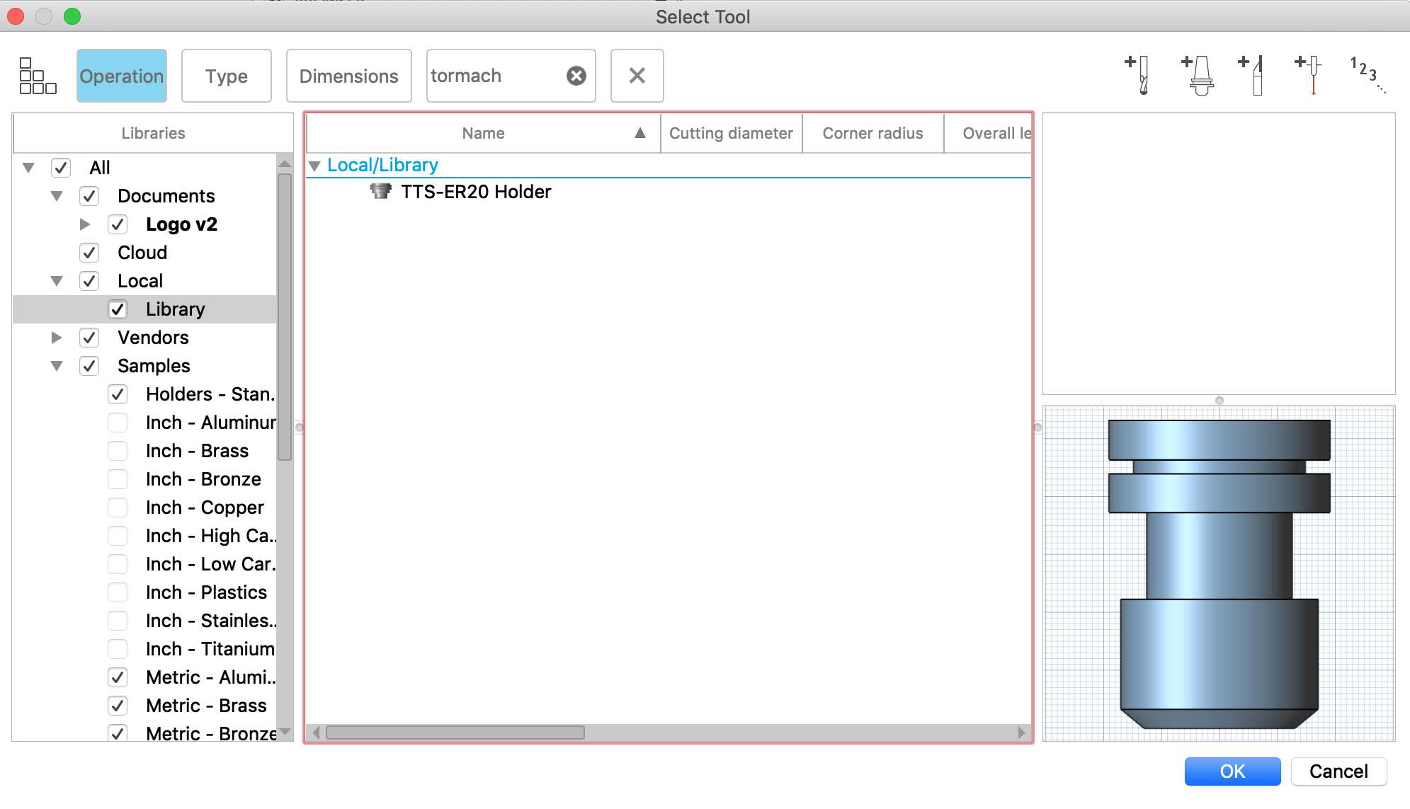
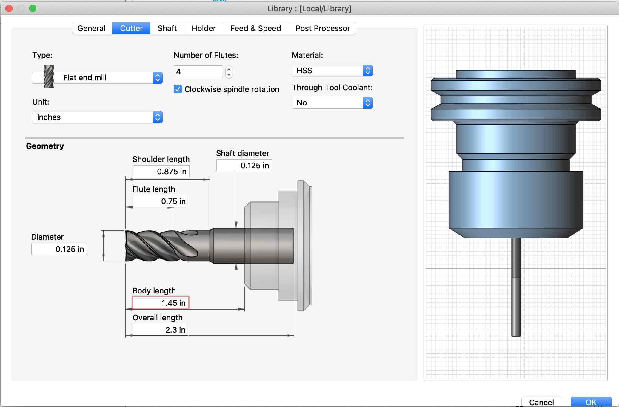
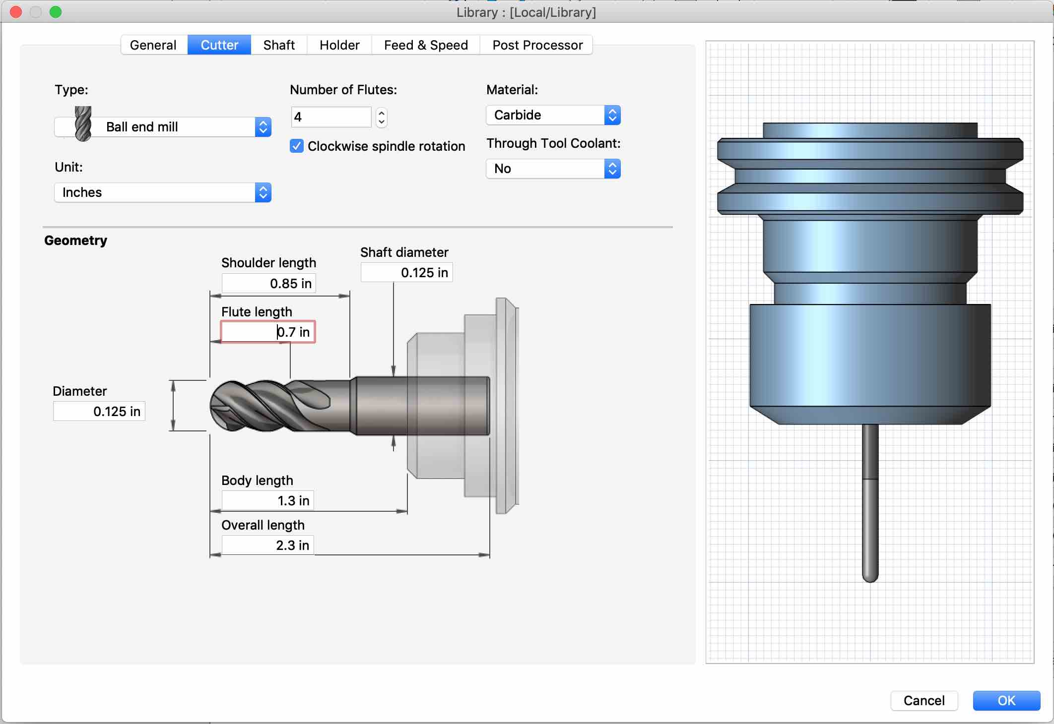
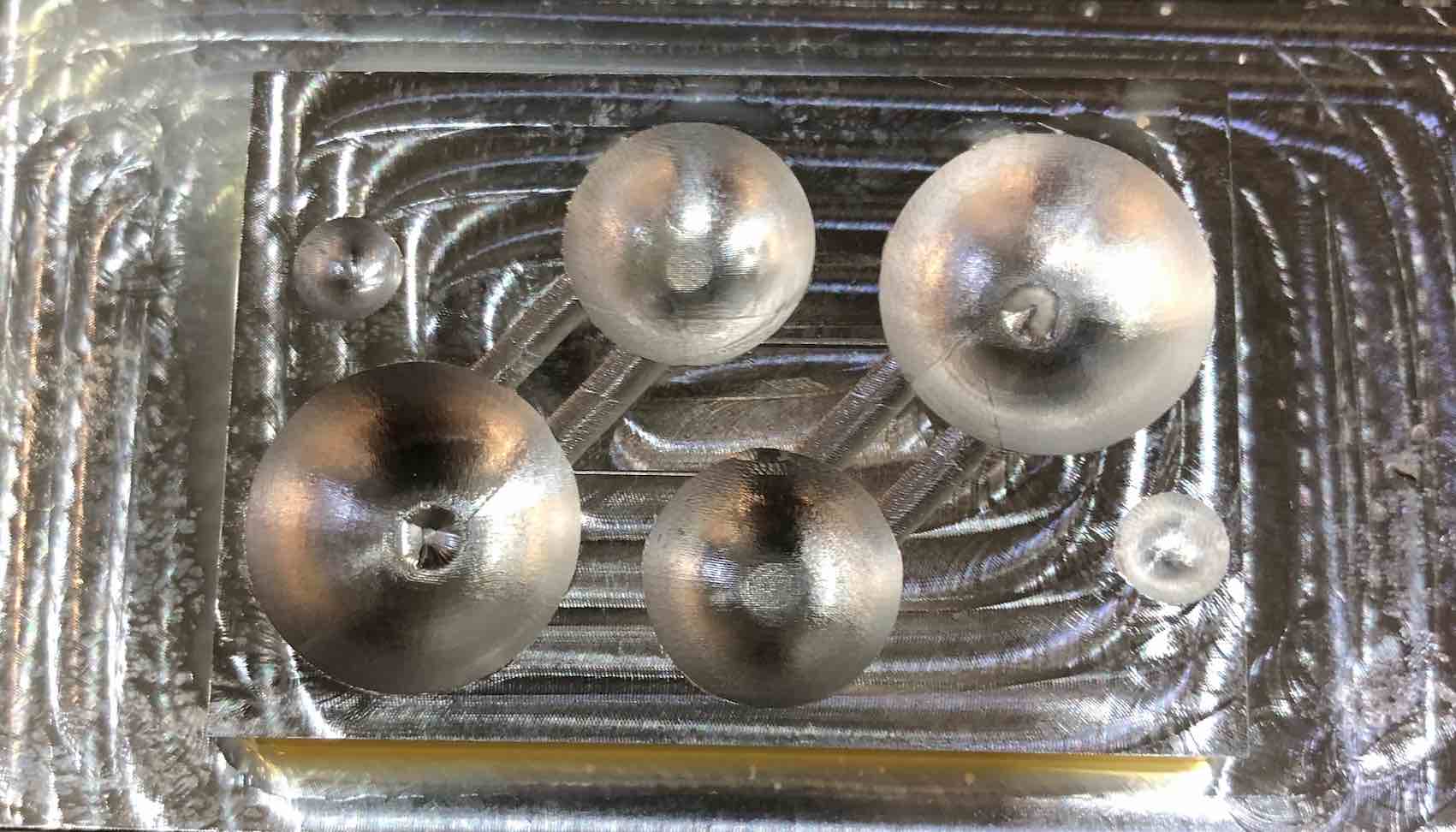
One the job setup was complete, I proceeded to add the holder and tools I will be using for this job. I chose to use a 3/8 inch flat 2-flute endmill to do the initial adaptive cut and material removal, leaving behind some extra stock for removal during the finishing jobs. Then I used 1/8 inch ballnose 4-flute endmill using a morphed spiral technique for the finishing of the larger spheres. Then, I used a 2-flute 1/16 flat nose to finish the horizontal surfaces and perform morphed spiral roughing, leaving behind some stock for the two smallest spheres. Finally, I finished the the smaller spheres with a 2-flute ballnose endmill. All the tools were done by measurement using digital calipers.
Holder
Flat nose tool
Ball nose tool
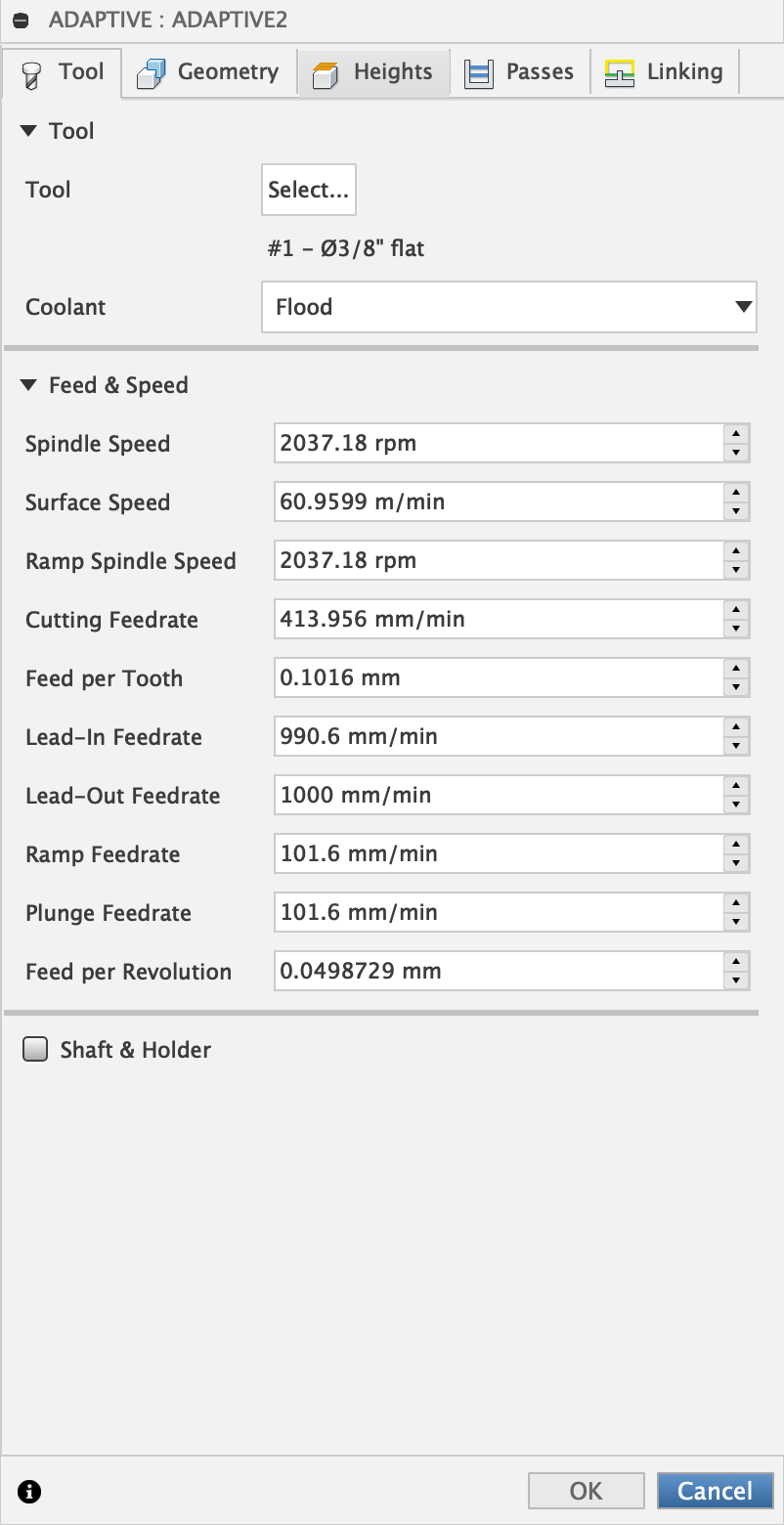
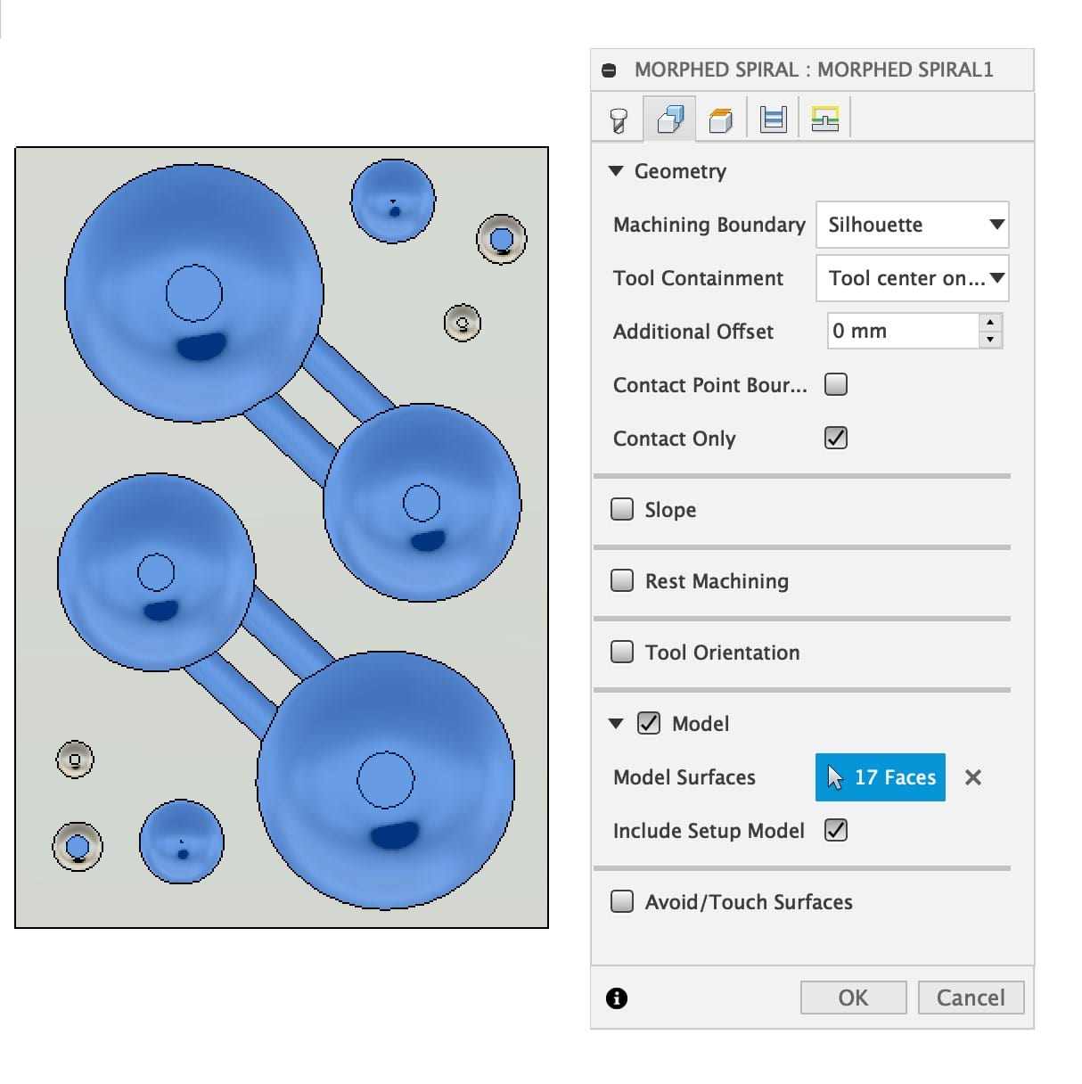
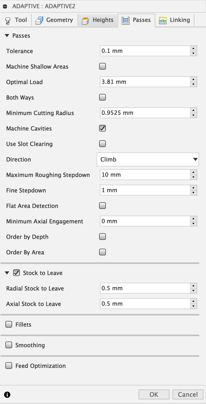
For each job , the technique is first picked, afterwhich, the speeds and parameters are set. The area in which the machine is allowed to work, as well as areas that this job will be performing can be specified. For roughing jobs, the stock to leave can be specified. For finishing jobs, the stepover and stepdowns can also be specified to achieve the desired precision and quality.
Spindle and endmill settings
Job settings (area)
Stock to leave and steps
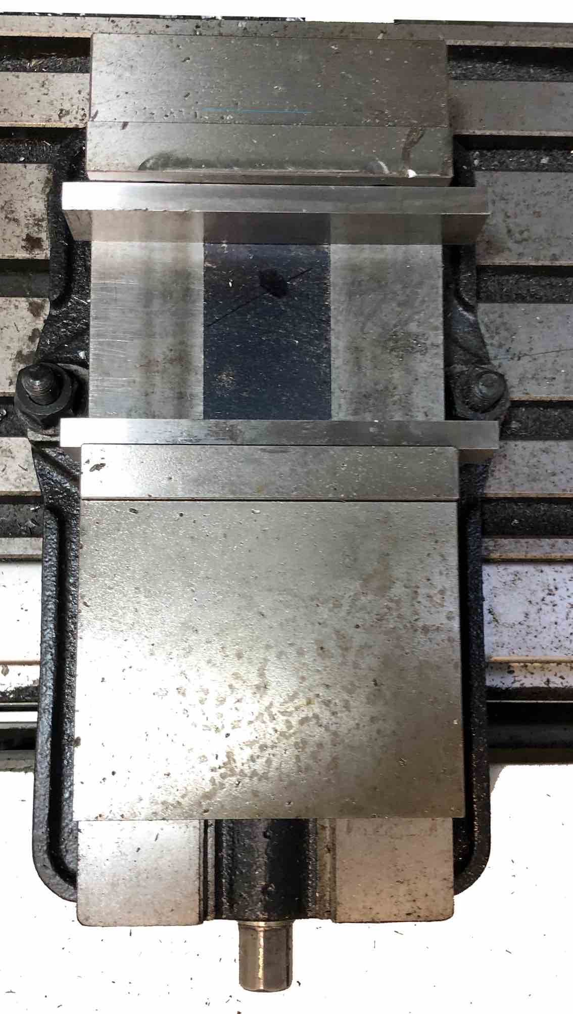
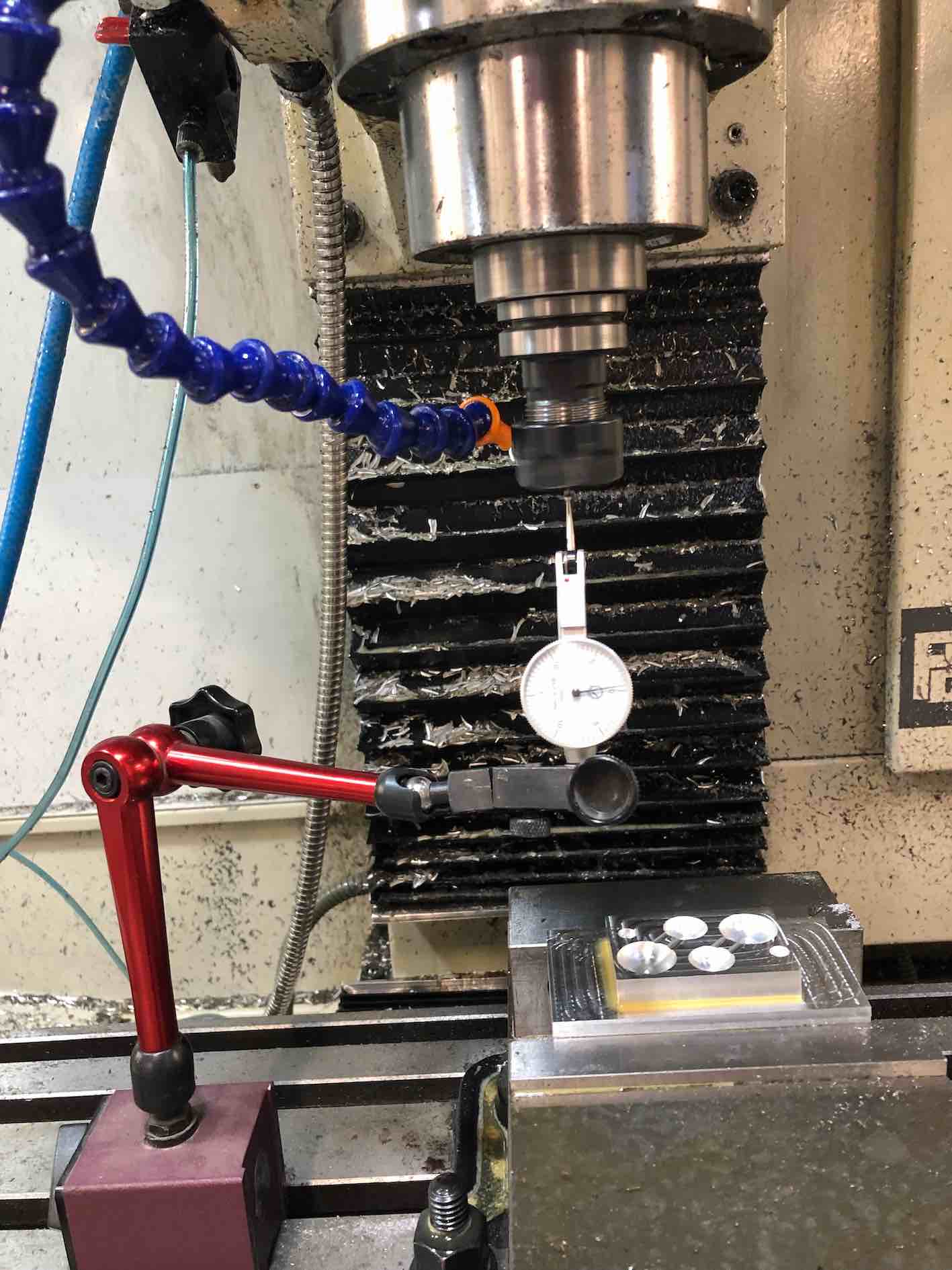
Before starting the milling job on the Tormach 1100 CNC, I placed parallel bars, onto which I placed the aluminum block. This ensured the block had all its sides at equal points on the same plane. Then after installing the tool to be used, I checked if there was any stability problem. To do this I fixed an angular dial and set it against the tool. Once the tool started turning, minimal changes in the reading ensure stability. Finally I used the edge finder to find the 0. It is basically a shank attached to a spring, which achieves flushness once the edge is sensed.
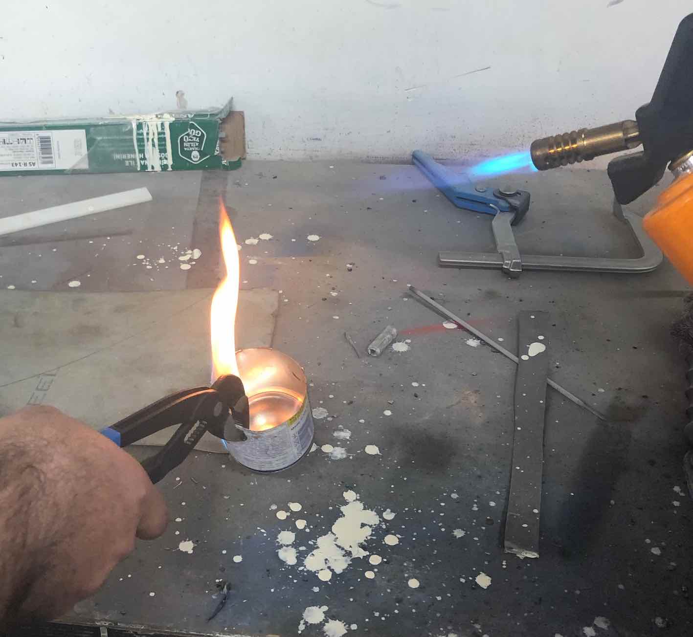
After all the jobs where done, my part was ready to have lead cast into it.
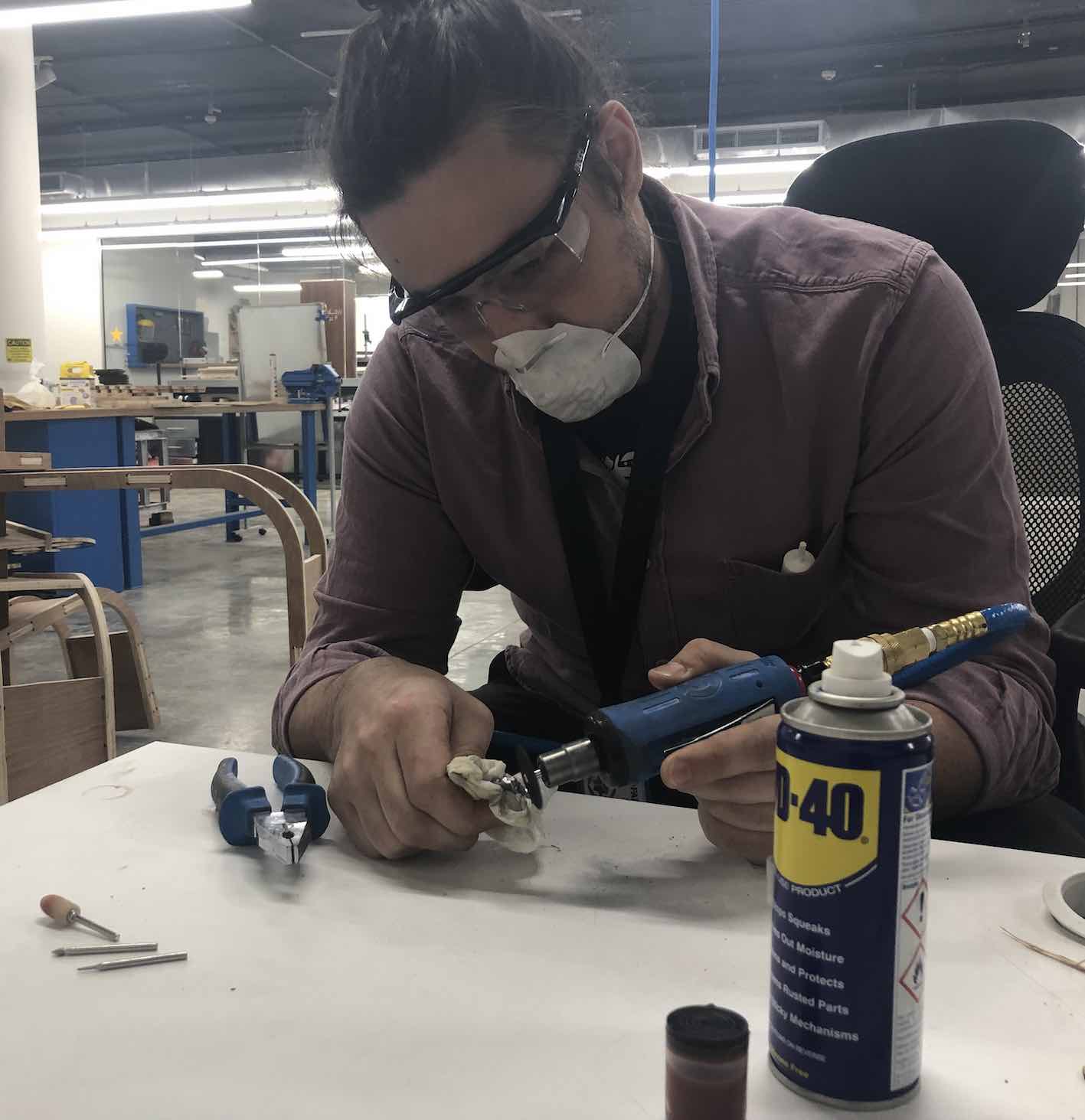
The lead was heated up using a propane blowtorch in a steel can, and the seperate bubbles were seperated and finished using a dremmel tool
Molding and casting the back panel and logo
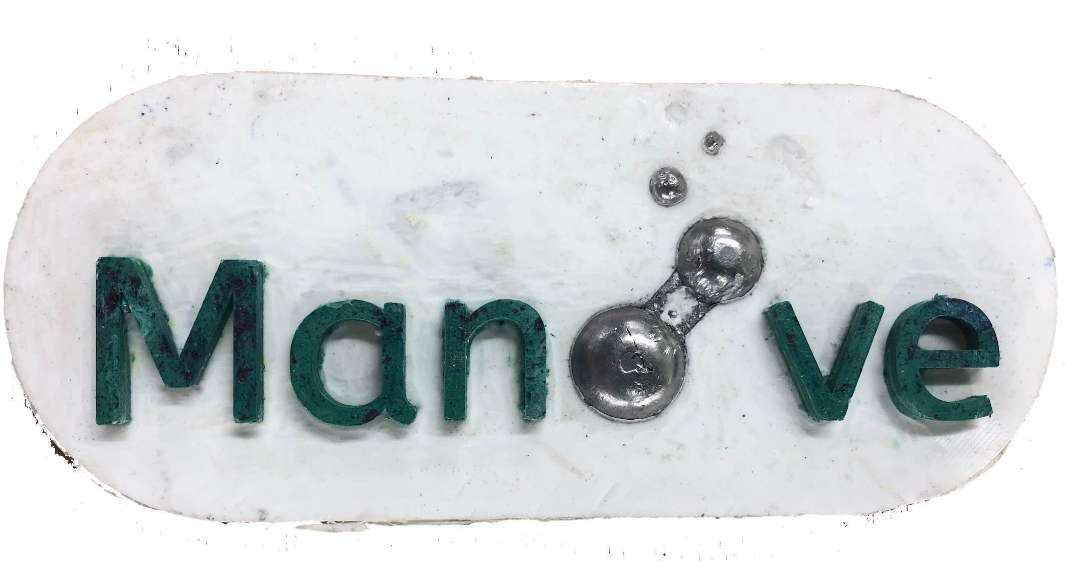
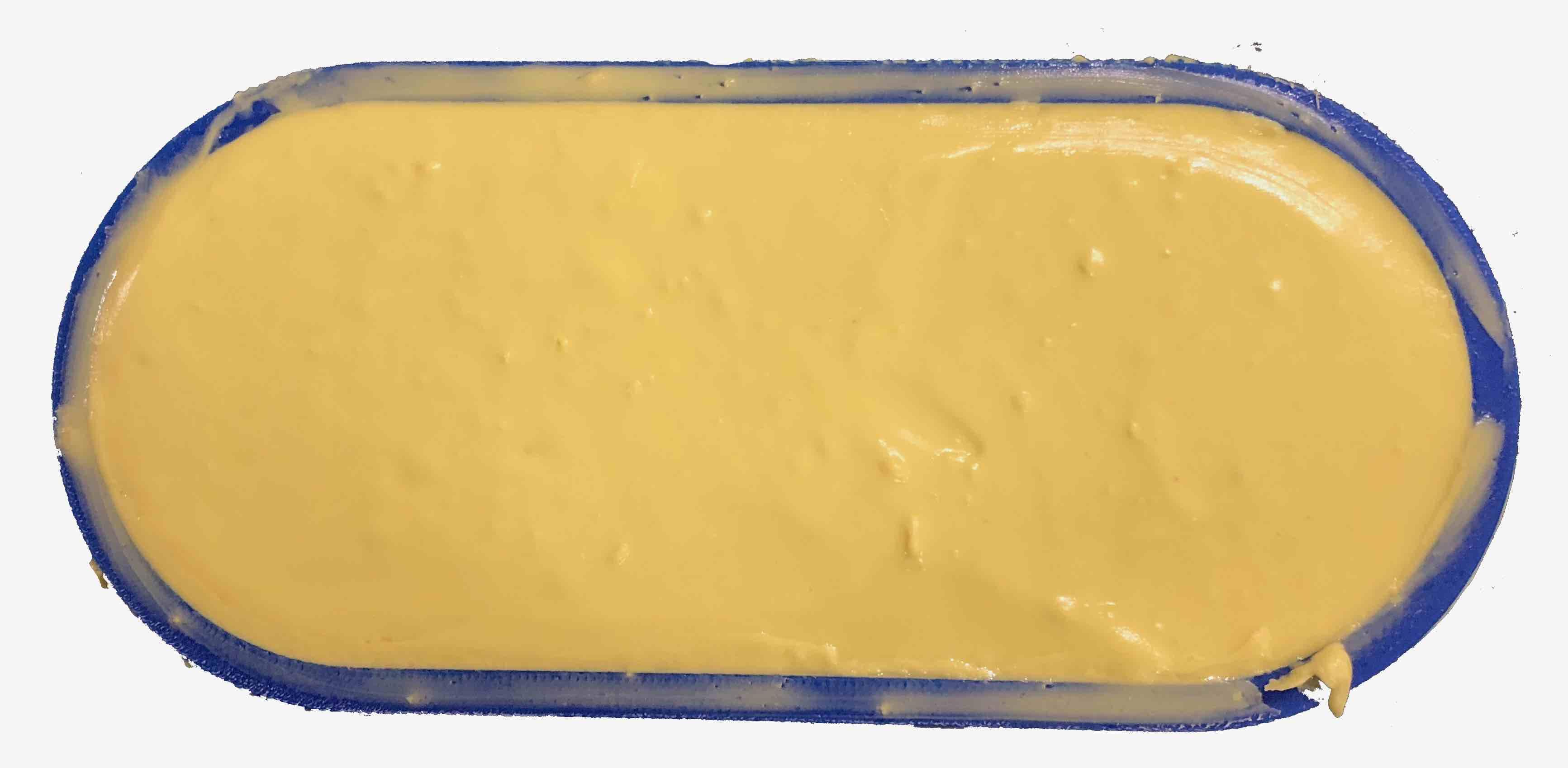
As mentioned previously, I 3D printed a model of the logo including the back panel. I then used some polysterene and a nylon bag to make a mold of this anti-mold using of Sorta-Clear 37. Sortaclear is mixed with a equal A to B volume mixing ratio, I chose this because it is the most advisable material available for use with resin according to the . Once the mold set. I mixed some Smooth-cast-305 liquid plastic, which is medium setting liquid plastic and is mixed using an equal A to B mixing ratio, as specified in the . I added some blue and yellow dye until I achieved the teal/turqoise colour I was aiming for, not mixing to much to create an inconsistent color effect. I used droppers for this process, as it was a small ammount and I needed to ensure the resin is poured directly into each letter and does not overflow. Once the letters were set, I placed the cast lead bubbles and poured non-pigmented white liquid plastic over it to form the back panel. Below is the resulting part. It is important to keep in mind the short 7 minute pot life of the Smooth-cast 305 liquid plastic and make sure all required tools and components are in front of you before starting the mixing process. NOTE: In the next section is a full video presenting the complete process.
Molding and casting the front capsule
After 3D printing the printing the piece shown on the right, reading through the specifications and then consulting with my instructors made me realize that casting such an ammount of liquid plastic in a PLA mold is going to heat up, ruin the mold and possibly fuse with the plastic mold. Hence, I had to rethink my approach.
I decided to use some dental algenate I had on hand to cast the model, and then take make a mold out of a material able to withstand the liquid plastic's heat. Dental algenate is a very tricky material to master, as it needs to be mixed with water to make a paste within a very short window of time.
I then placed the algenate model on some ceran wrap, cut out the buttom of an ice-cream container, put vaseline on the edges of the container and placed it on top of the algenate model. I then mixed some plaster and poured it through the whole. Now I had a mold that I'd be able to pour resin in and not worry about any thermal reactions.
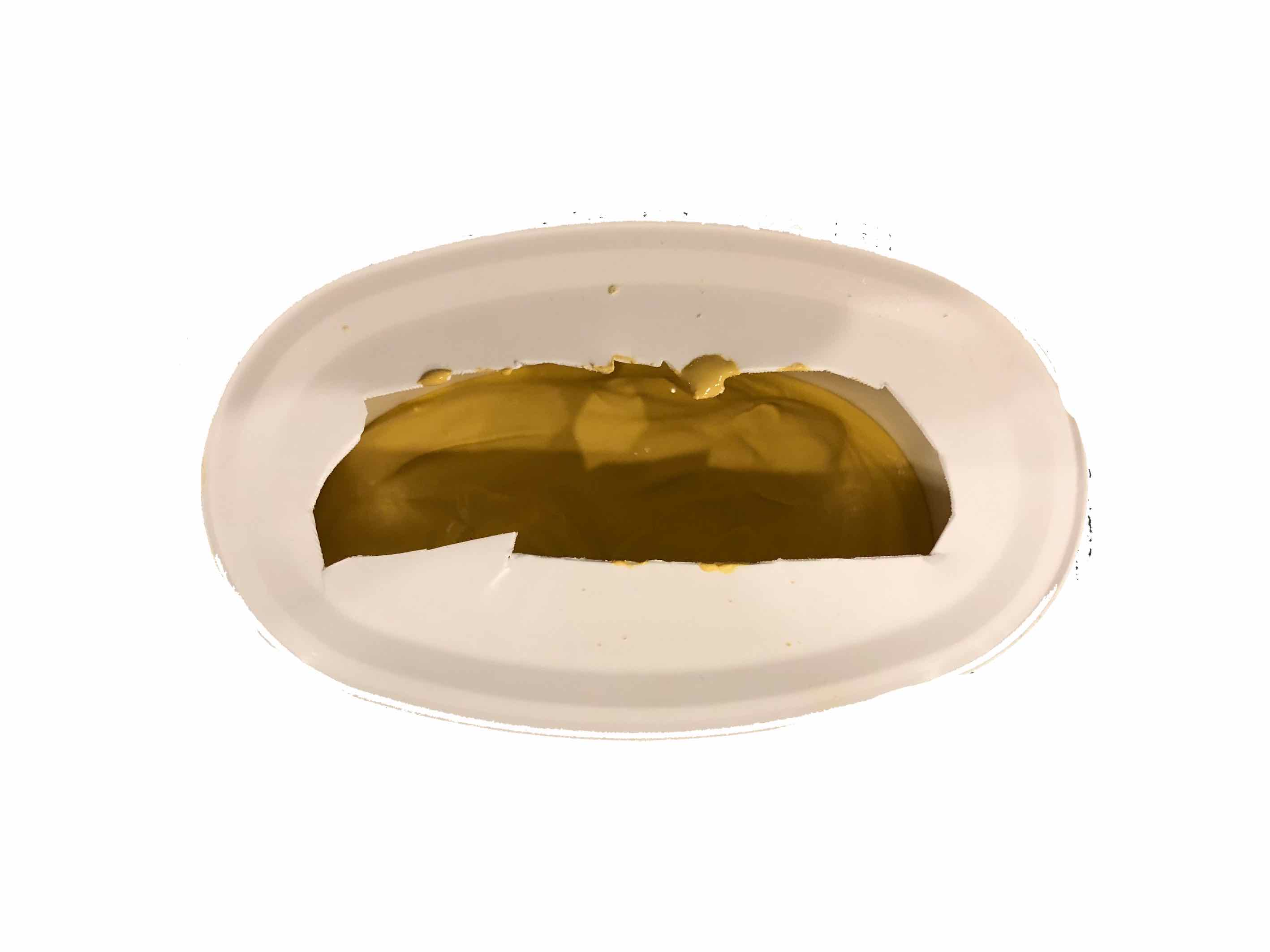
For the final stage of the process, I bought some local clear resin, which is mixed 15g of hardner for every 1KG of resin. The only datasheet were the verbal instructions of the shop owner. I poured this resin into the plaster cast, then placed the backpanel and logo on top of it. The piece needed some sanding with high grit paper to achieve a smooth surface. The picture on the right is the first version
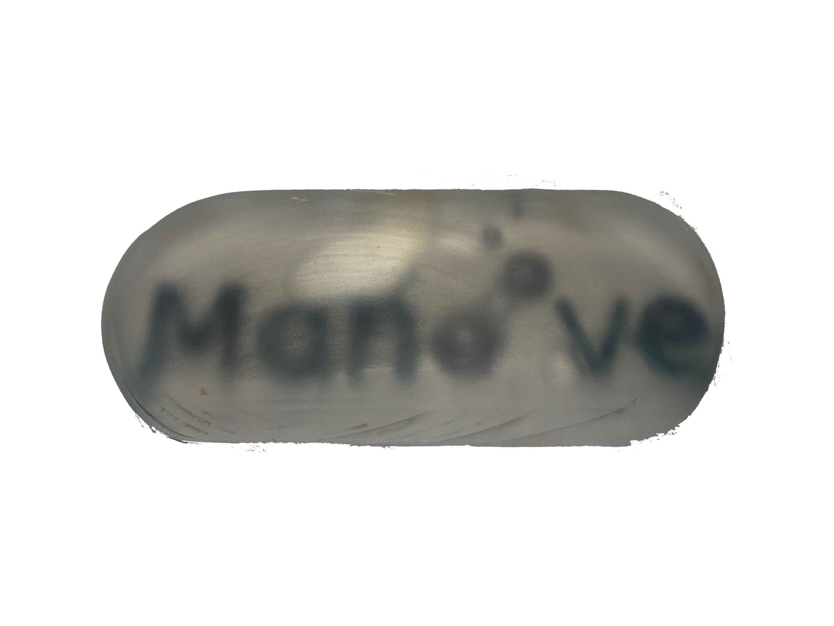
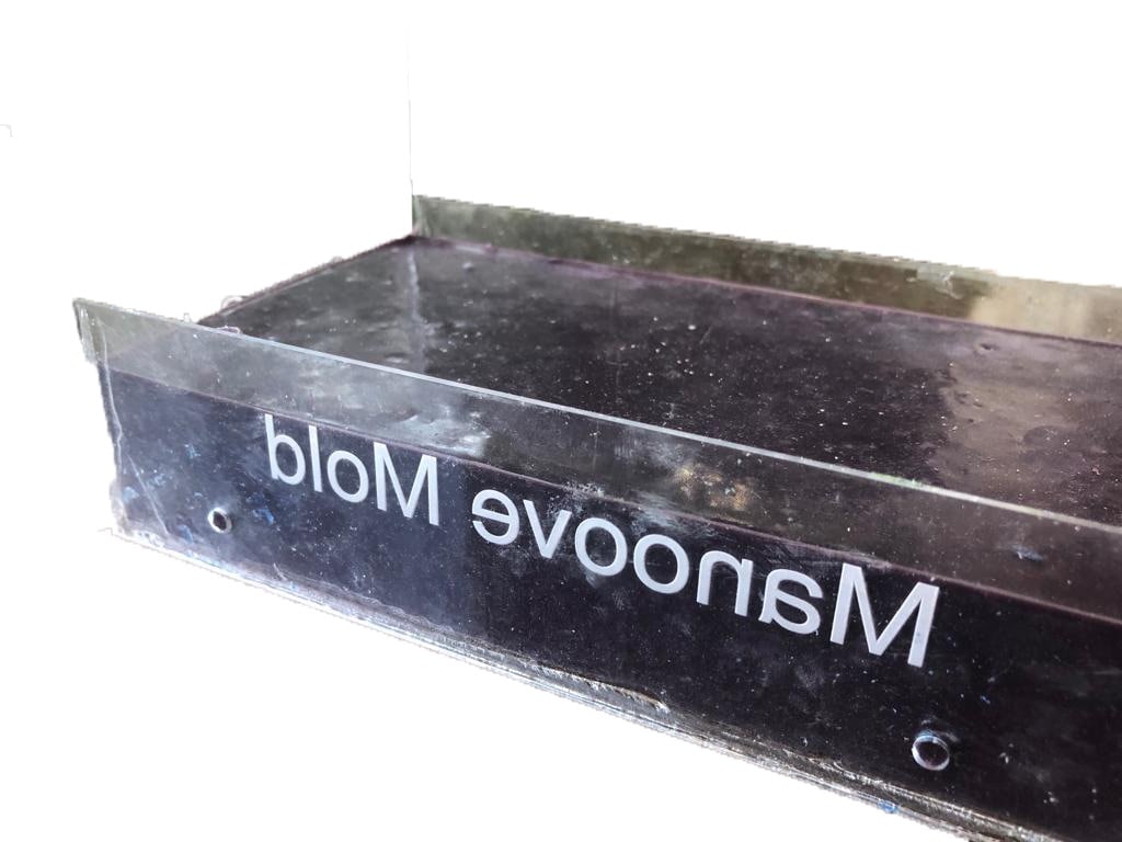
I repeated the process by making an acrylic mold instead of a plaster mold for a smoother surface and better finish. After it was ready, I sanded the clear resin to give it a mirror finish using wet sand paper, starting from 320 to 800, 1000, 1500, 2000 grit in order. Below is the second version which looks much clearer and better in terms of finish. It is important to note that the yellowish colour is due to a heatwave that affected the resin as I had it stored at home, withouth which the clear resin would be completely colourless.
Acrylic mold for the silicone mold
Silicone mold
Sanded clear logo
Making a mold for the forearm rest
I took advantage of the materials available this week to make a mold for the forarm rest. The process entailed placing my arm on a piece of mixed dental algenate to form the surface topograph, and then pouring plaster on the surface to form a cast of the bottom of my forearm.
Files
Please find all the files required, if you feel like casting your own:
-min.png)