Embedded Programming
In this week's assignment we had to read the microcontroler data sheet and program our board to do something, using as many different programming languages and programming environments as possible.
Group Assignment
For this week's group assignment we had to compare the performance and development workflows for other architectures. You can find the documentaion here.
Arduino Code
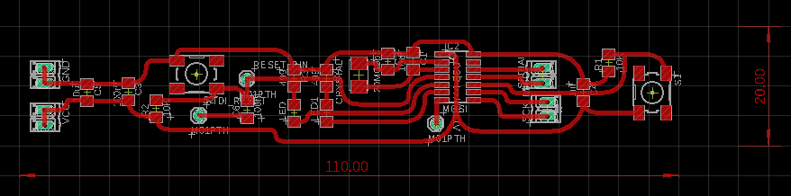
Arduino code is written in C++ which is a human-readable programming language. In the Electronics Design week I already made my own flexible pcb, which I will use to accomplish this week's task. This pcb has two buttons (input) and two leds (output).
I used the ATtiny44 MCU as microcontroller. Below you can see it's pinout.
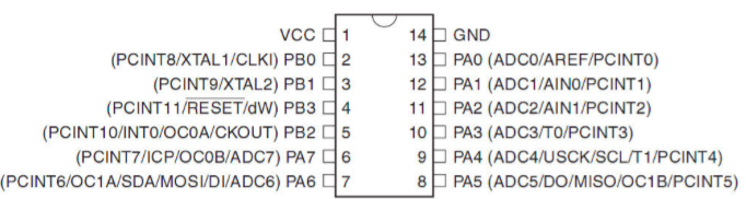
For this assignment I am using the PCB I made in the Electronics Design week .
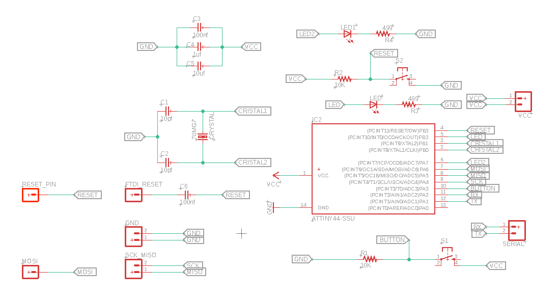
The goal is to make the two LED blink according to the press of the button. The pin in the code 8 corresponds to the PB2 pin of the Hello Board is connected to the LED. Pin A7 corresponds to the PA7 pin which is also connected to the LED. The button Pin is connedted to the PA3 pin, which corresponds to the A3 pon in the code.
#define buttonPin A3
#define LED1 A7
#define LED2 8
int buttonState = 0;

void setup() {
pinMode(LED1, OUTPUT);
pinMode(LED2, OUTPUT);
pinMode(buttonPin, INPUT);
}

void loop() {

buttonState = digitalRead(buttonPin);

if (buttonState == HIGH) {
digitalWrite(LED1, HIGH);
digitalWrite(LED2, LOW);
} else {
digitalWrite(LED1, LOW);
digitalWrite(LED2, HIGH);
}
}
C-Code
#include <avr/io.h>
void main(void) {
DDRD &= _BV(DDA8); // PA8 as Output
DDRD &= _ BV(DDA7); // PA7 as Output
DDRD &= ~(1<<DDA3); // PA3 as Input

PORTD |= (1<<PA3); // Pullup PA3

while(1) {

if(~PINA & (1<<PA3)); // Button pressed
  /* set pin 7 high to turn led on and 8 to low */
  PORTB |= _BV(PORTA8);
   PORTB &= ~_BV(PORTA7);
else
/* set pin 8 low to turn led off */
  PORTB &= ~_BV(PORTA8);
  PORTB |= _BV(PORTA7);
}
Programming
To give the microcontroller functionality I used a FabISP as ISP, but you could also use something else (for example the Arduino).We connect the FabISP with our board via the SPI pins and thus avoid the 5V connection. On the other hand we connect the FTDI cable to the microcontroller board which is connected to the other UART interface.
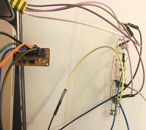
Before connecting the PCB check all the connections with the multimeter, to be sure that you have a closed circuit and that you do not have any shorted circuit. To "burn the fuses" or bootload the board, one needs to download the FabISP firmware and extract it somewhere in the PC.
Next, create a Ledfile.make file, that uploads the buttonBlinkLed.c code we just created. Changes this file to your MCU type.
PROJECT=buttonBlinkLed
SOURCES=$(PROJECT).c
MMCU=attiny44
MCU=t44
F_CPU = 20000000
CFLAGS=-mmcu=$(MMCU) -Wall -Os -DF_CPU=$(F_CPU)

program-usbtiny: $(PROJECT).hex
 avrdude -p $(MCU) -P usb -c usbtiny -U  flash:w:$(PROJECT).c.hex
program-usbtiny-fuses: $(PROJECT).hex
 avrdude -p $(MCU) -P usb -c usbtiny -U lfuse:w:0x5E:m
Having this Ledfile as well as our buttonBlinkLed.c code, we can go ahead and burn the fuses onto our board. Similar to the Electronics Design week.
make -f Ledfile.make
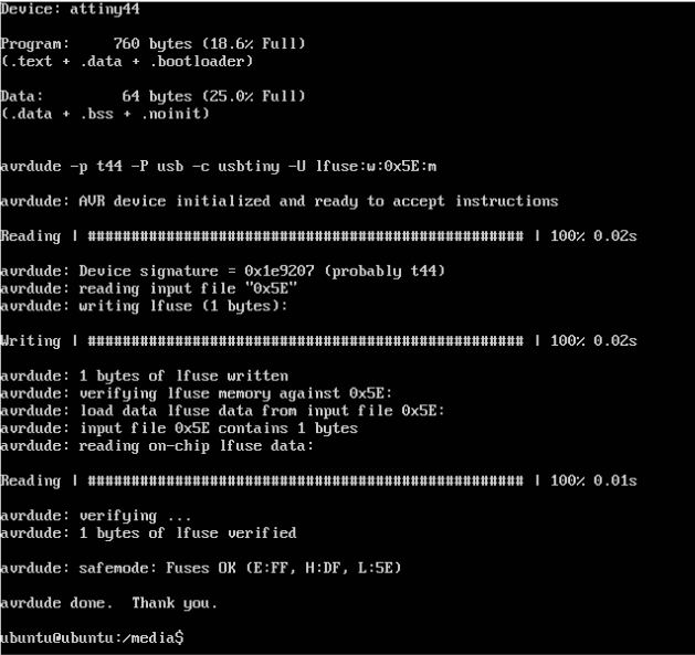
Here we are burning the fuses to the board.
make -f Ledfile.make program-usbtiny-fuses
Finally we write the new program into our board.
make -f makefile.make program-usbtiny