Group Assignment: Electronics Design
For this week's group assignment the scope was to test the equipment in our lab and to observe the operation of a microcontroller circuit board.
The digital Oscilloscope
An oscilloscope is an item of electronics test equipment that outputs signals in waveforms. In this way it is easy to see any problems occurring in an electronics circuit. A digital oscilloscope is a complex electronic device composed of various software and electronic hardware modules that work together to capture, process, display and store data that represents the signals of interest of an operator. When connected to a power source through a probe, the oscilloscope displays the corresponding real-time waveform immediately. Some of the advantages of a digital oscilloscope over analog oscilloscope include the scope’s ability to store digital data for later viewing, upload to a computer, generate a hard copy or store on a diskette and its capacity to instantly make measurements on the digital data.
Oscilloscope Calibration
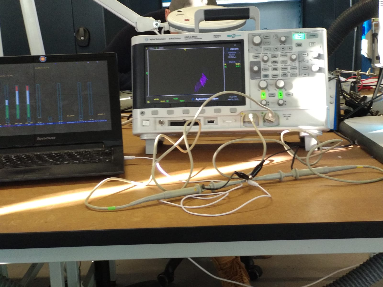
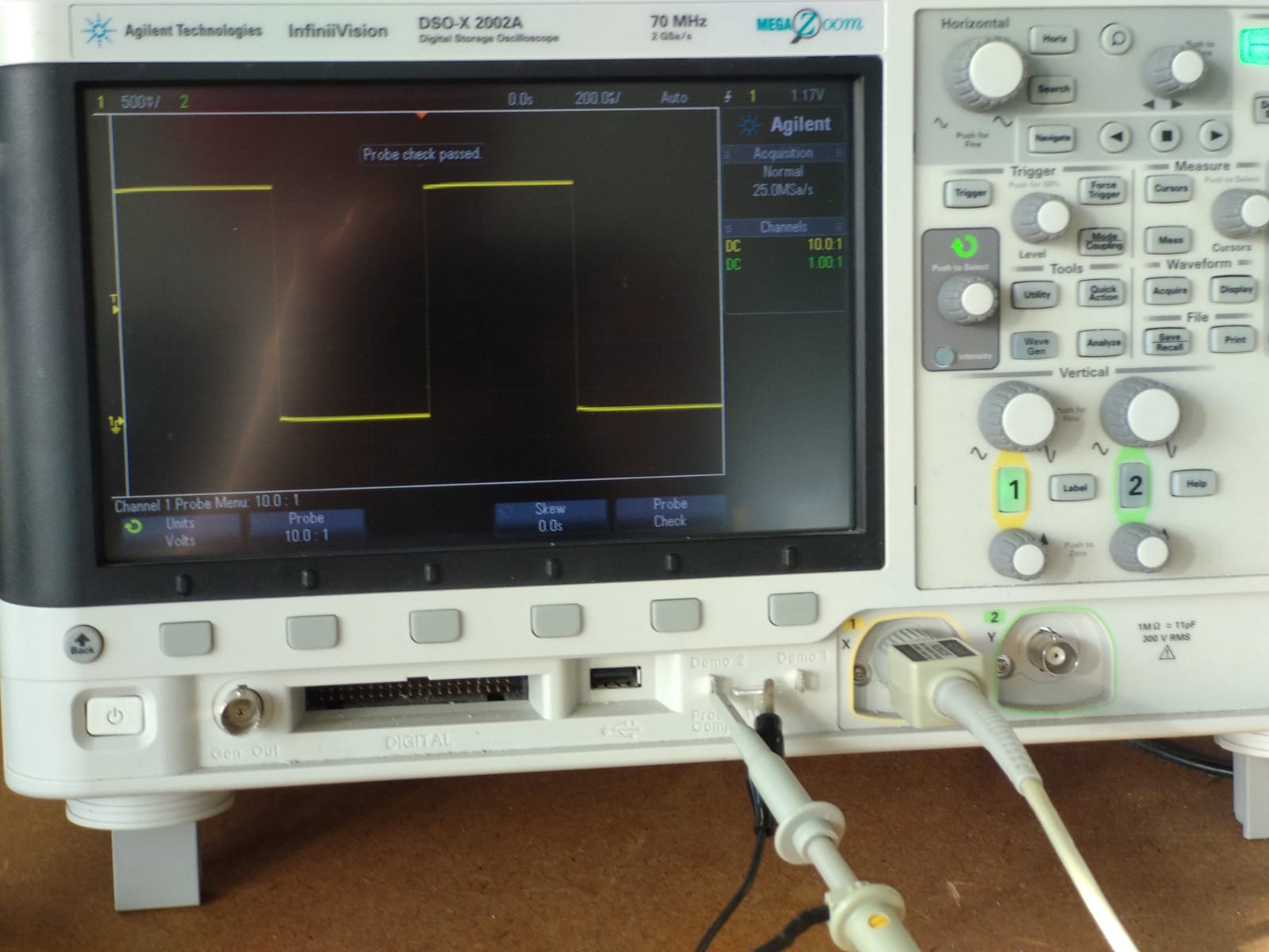
To complete this assignment we used the Agilent Technologies DSO-X 2002A digital oscilloscope. Calibrating your oscilloscope for the probe you are using is the first thing you want to do. To do this you connected the probe to the demo signal generator of the oscilloscope itself. This should generate a square wave on the display. It should look like this after calibration.
Connecting the Probe to a Voltage Regulator
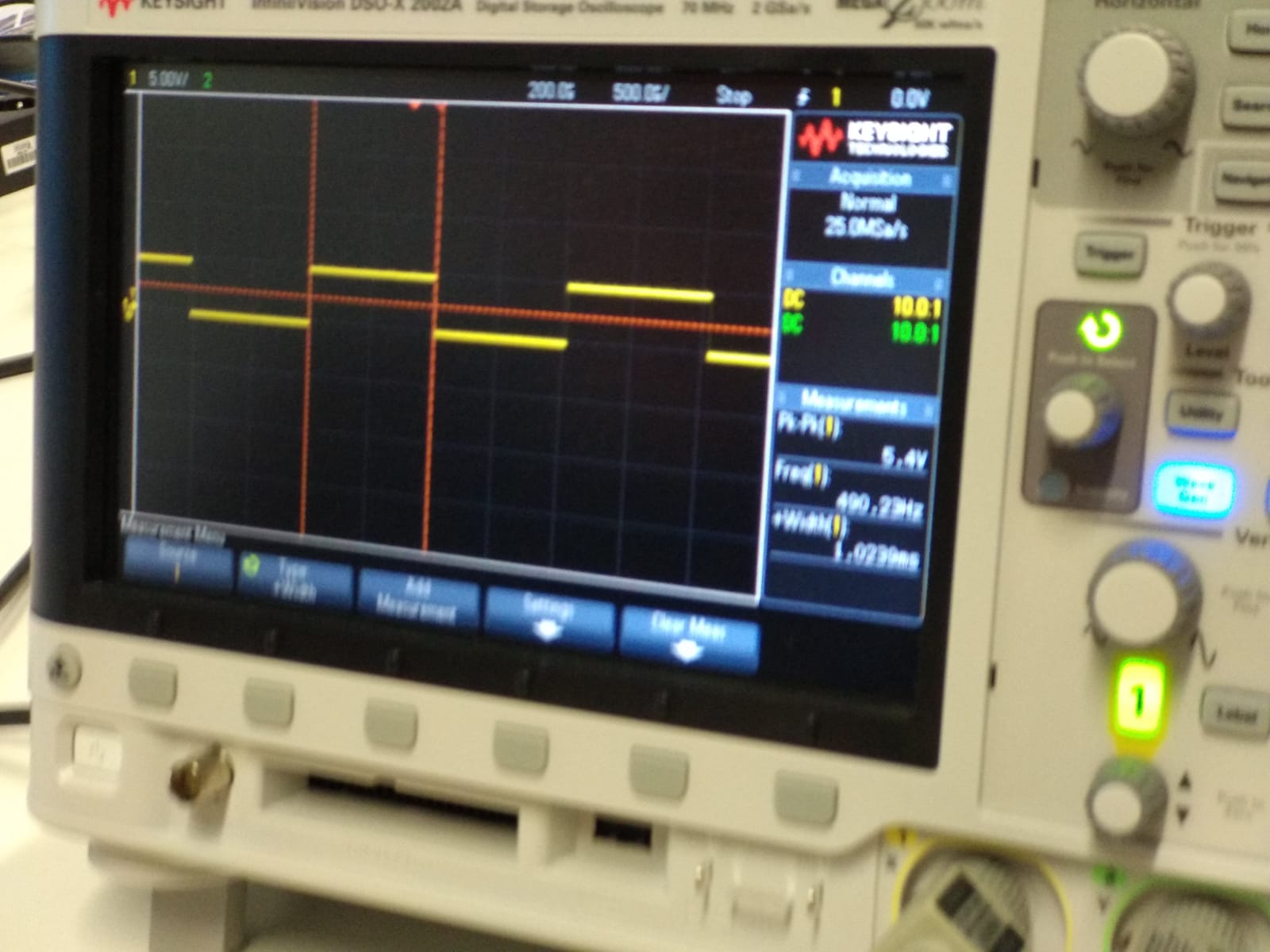
Next we connected the second probe and used it to compare the input and output of a 3.3V voltage regulator. We had to turn on the second signal using the green "2" button on the lower part of the control panel.
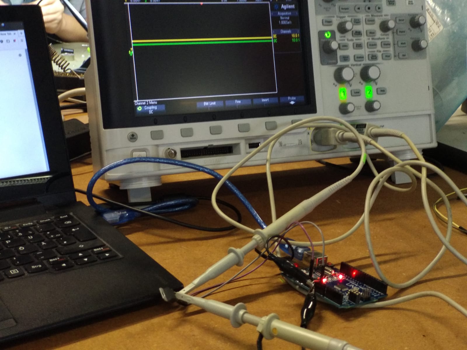
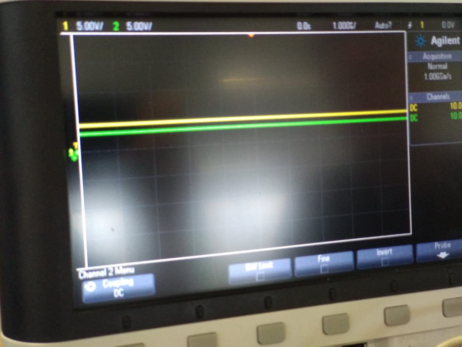
Here we could clearly see that the green line - the one belonging to the probe connected to the output of the regulator - was lower than the yellow one at 5V.
Connecting the Probe to a Potentiometer
Out next test was done with a potentiometer. For this the horizontal and vertical scale had to be adjusted using the knobs on the control panel. At the right scale settings we could see the curve change when we turned the potentiometer. The higher the resistance the lower the curve.
Connecting the Probe to an Analog Pin
Next we probed the analog pin of an arduino. This showed that even those pins can only be set to high or low and not values inbetween. When we set the pin to 100 the output was at 0, when we set it to 255 it was at 5V. To get a comparison we loaded the "Fade" example from the ArduinoIDE and probed the digital pin 9. Here we could see how the Pulse Width Modulation (PWM) works to generate pseudo analog signals by generating different frequency pulses of digital output. The lower the desired signal the shorter the pulses.
When setting the PWM to one value instead of fading and adjusting the horizontal scale so we are looking at only one edge of the rising signal we could also observe that switching from low to high takes around 20ns. First the signal overshoots to around 6V at 10ns and then adjusts to 5V at 20ns. After around 100ns it stabilizes even more.
We also observed the Serial Clock (SCK) pin of the ArduinoISP. For this we first set the horizontal scale to the time span we wanted to record - in our case 200ms - and then pressed the "Single" button in the upper right corner to put the oscilloscope in single event mode instead of the one for continous live measurement. Then we started to program a board using the ISP. Now we could see how the ISP starts sending clock pulses.
Listening to Oscilloscope Music
The last thing we tried was listening to the album Oscilloscope Music by Jerobeam Fenderson, which is made to be listened to as well as beeing watched on an oscilloscope. We connected the audio output to the oscilloscope and used the XY time mode to compare the left and right channels. This is done by pressing the "Horiz" key to get into the Horizontal Menu and then pressing the button below the Time Mode menu. Now the light over the selection knob is lighting up, signaling that we can use it to select the desired time mode. In our case we selected "XY" and left the menu using the "Back" button. After adjusting the scales of the two signals this worked as expected and we could see the drawings on the screen of the oscilloscope.