Group Assignment: Computer-Controlled Machining
For this week's group assignment we had to test runout, alignment, speeds, feeds, and toolpaths of our CNC machine.
CNC Machine
CNC (Computer Numerical Control) machining is a subtractive manufacturing technology. Objects are created by removing material from a solid block using a variety of cutting tools. Almost every material can be CNC machined such as metals, plastics, foam, and wood. The basic CNC process can be broken down into 3 steps. The engineer first designs the CAD model of the part. The machinist then turns the CAD file into a CNC program (G-code) and sets up the machine. Finally, the CNC system executes all machining operations with little supervision, removing material and creating the objects. You can have a 3 axis or a 5 axis CNC machine.
Working with the CNC Machine
The machine we use is the EasyWorker MasterPro 2513. This machine comes with special software which can load DXF files and convert them into GCODE files. Several important steps are required to troubleshoot the machine.
First you have to turn the main switch to turn on the machine.

Then you have to reset the machine and start it.

Next, make sure the bed of the machine is clear before proceeding and then start the CNC4.01 software.


After starting the software, you will have to home the machine. Below you can see the interface of the software, which shows a vector model in the middle, which displays the job directly as soon as you load it into the software. On the right side one can see the coordinates of the X, Y and Z axes, the GCODE executed by the machine and the time required to execute the job. At the moment we are in the operation tab. Here the user can operate the machine and change things such as the tool, the feed rate and starting or stoping the job.

To home the machine you can use the remote control. There is a side button on the right side of the control, which must be pressed simultaneously with the buttons on the remote control. Here you can find the basic controls, as they can be found in the software.

Next you will have to set the zero point, which is the starting point of your job. To do this use the remote control. By pressing the shift button and one of the axes you can move at high speed. In our case, the origin point is always the lower left corner. To check if you have set the X and Y coordinates, go to the software and make sure it displays zero.

To adjust the Z-axis, you must use the sensor that measures the exact height of the bed. You can find the sensor on the head of the machine. To set the Z point we need a second person that holds the sensor. Always check if the person is ready, since the machine is going to move.


Once you have set the origin point, you can switch to the Program tab, where we generate the GCODE. First of all we make sure that we select the lower left as orgin point of the DXF. Then we first select the output layer and then we can configure the settings with which we execute the job. Also make sure you select the correct mask. For an inside or outside cut, select the offset mask. In order to achieve the best result, we start with the inside job.
It is very critical that you set the right tool number, safe-Z height and final-Z height.
After confirming the settings you can generate the GCODE.
Before launching the job there are some crytical aspects to consider. These are:


Testing the CNC Machine
We have created a series of test tasks in which drilling, engraving and cutting in straight lines and curves was tested using our CNC machine.
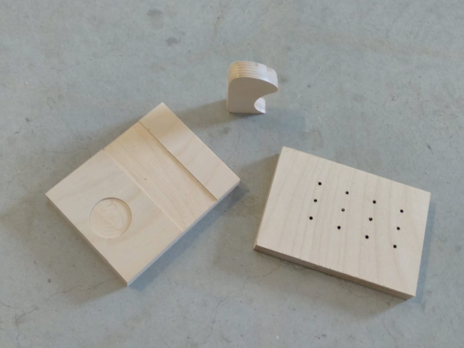
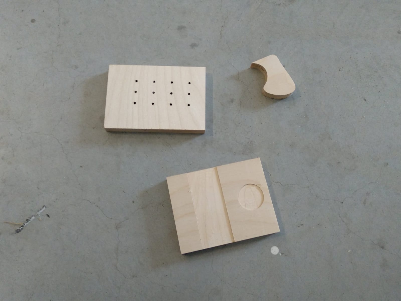
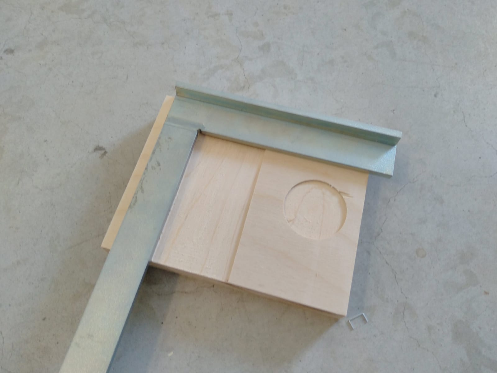
On the left side one can see the engraving test, the small part in the middle is a section of a bezier curve and the right part has several drillings. All of these turned out to be highly accurate, and with exactly the dimensons as on the design files.
In addition to the visual comparison of our workpieces with the design files, we also measured the alignment and toolpaths. One of the first jobs failed because the piece of wood was moving on the machine bed, resulting in very inaccurate cuts, the final jobs where very precise.
When it comes to runout we measured the drilled holes with a 0.1 mm precision caliper they were exactly the same as the designed size
Different feeds and speeds for different materials are documented in our pages
For the kerfing we found out that with our wood supplier we design the joints exactly the same as the slots and that fits perfectly, we tried +-0.1 mm as the imperfection of the material was less than what we could measure with the caliper; -0.1 was way too loose and +0.1 needed a lot of hammering that the wood almost cracked.
As can be seen on the second picture the lines have a perfect 90° angle and are completely straight.