Cintya
the cylindrical drawing machine
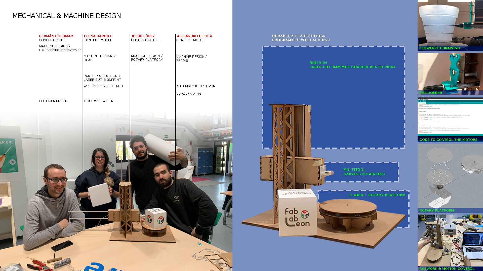
The team
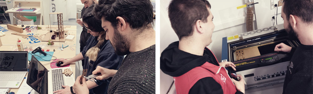
We are remote students supervised by our instructor Nuria Robles of Fab Lab Leon, so in order to do this group assingment, we decided to meet all together one weekend in Leon. The week before we worked on the design and, for having as much time as possible available there, we decided to bring the different pieces already fabricated. So in Leon we "only" had to assemble the machine and automate it.

Elena Cardiel
Fab Lab IE University

Germán Colomar
Fab Lab UE

Alejandro Ulecia
Fab Lab ESNE

Jesús López
Fab Lab ESNE
Idea. Concept
Before starting thinking about our machine, we decided to do depth research on the machines that other students had done in previous years. The ones that we found out more interested were: Peeler, Roto-Casting, Catapult, Lights Drawing.
We finally decided to use Nadia’s modules and we agreed to make a vertical lathe, with two arms, a rotatory pedestal and various heads to generate different shapes, textures and designs.
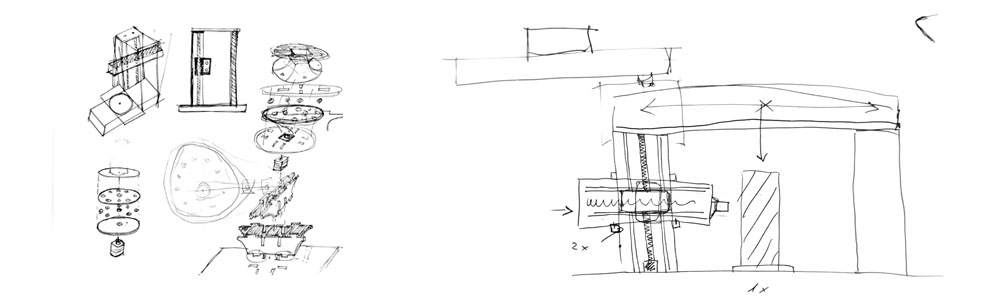
Design
We decided to divide this part of the work is three parts: Alejandro Ulecia would be in charge of the structure (the arms and base of the machine); Jesús López would design the rotatory platform; and Elena Cardiel would make the different heads.
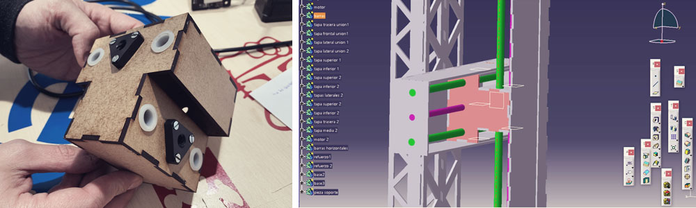
Structure, arms and base: With the measurements taken from the previous Leon's machine in 2016, for the design of the structure, we decided to make the modules from scratch because, in our machine, the size of one of them will be smaller than a normal module. We started making the base and the vertical arm, which has the same measures as 2016 file. With the vertical module created, we proceeded to design the horizontal module, which is much shorter than the normal modules and that is attached to the vertical module with a central piece shared for both axes.
Apart from that, our idea was to recycle the calibrated bars, the motors and the rest of the mechanical pieces used in the old machine.
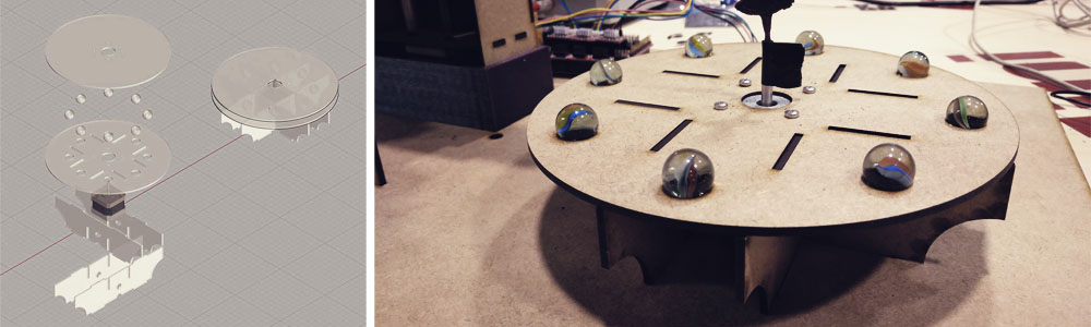
Rotatory platform: For this task, we decided to have a maximum surface of Ø200mm.. The rotatory base is supported by four "beams" and in the free center space is the motor. Then eight marbles, acting as bearings, allows the upper base to turn, which is attached to the central axis of the motor.
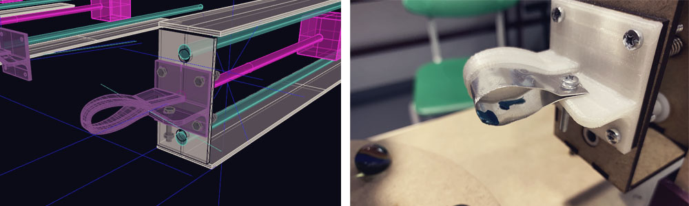
Tools head: our first idea was to have a sheet of metal which we can fold and create like a “knife” that can “peel” the surface of a cylinder of FOAM. With this in mind, we placed the center of the attachment aligned to the center of the horizontal motor, which is also aligned with the center of the rotary pedestal. The blade has a bit in angle (15º), and the end of the blade is also aligned with the center of the horizontal motor. We designed a “profile”, with a “rail” where to put the sheet of metal inside, so it will never lose the shape. However, after assembling and trying the machine we realized that this head doesn't work very well, even if we sharp the sheet of metal, the motors aren’t powerful enough to cut the foam. We tried with clay and it worked good but not with the FOAM. (Later you can find videos showing how it worked, or did not work).
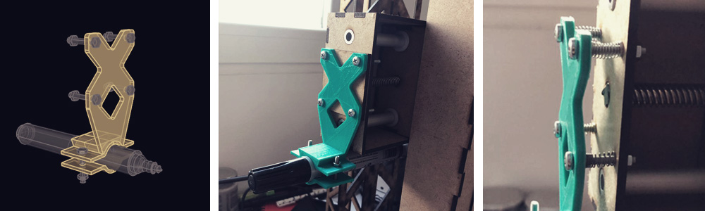
Then we decided to design a head to hold a marker, as we discovered that our machine worked better as a "cylindrical drawing machine" rather than as a "vertical lathe". This new head shares the same holes for the screws than the previous one and is also centered with the arms and the rotatory platform, but we decided to place the marker in the bottom part of the arm, being able in this way to draw very close to the rotatory base. We also included springs in each screw, avoiding future problems if the object that we want to paint is not perfectly circular.
To know more information about the design please visit Alejandro Ulecia's webpage , Jesús Lopez's webpage , and Elena Cardiel's webpage .
Fabrication and Assembly
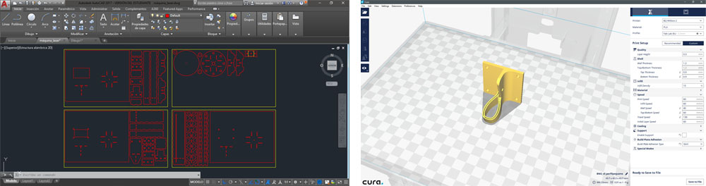
We decided to fabricate the main structure of the machine, base and rotatory platform in MDF of 3mm. by laser cutting, and the base and head attachments in PLA by 3D printing.
For the laser cutting, we put together the three parts of the design and we got the outline of the different pieces. We finally used almost 4 panels of MDF of 3mm of 810x450mm., as we decided to used a three-layer base to be sure that the machine was totally stable. It took around an hour to cut all the pieces.
At the same time, and after checking that the files were well done as a closed object, we prepared the files in CURA to be 3D Printed and we sent it to the machines. The base attachment took 2,5h. and the heads around 30 minutes each.
While assembling the machine we had to recut some pieces because we forgot to add the supports for the bars and endless screw. It only took fifteen minutes between preparing the file and cutting and we could complete the assembly.
We took around 2 hours to assemble the machine. To reinforce the structure we glued the MDF pieces with hot and white glue. We also had to cut one of the endless screws, as our horizontal module is smaller than the original Nadia's modules.
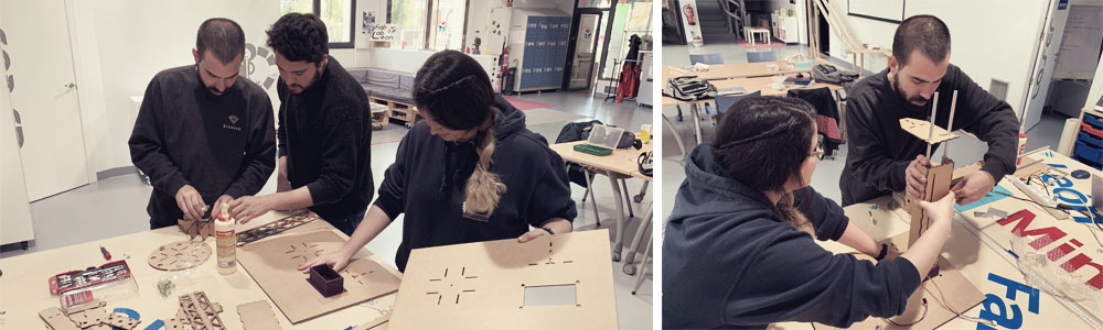
You can see below the fabrication and assembly process.
Mechanical movement: Operating it manually
Once de glue was completely dried, we could check if the machine worked and it did!! :) We could move the three axis without problems.
Programming 1.0
While part of the team was assembling the machine the other part was preparing the computer with the necessary plugins to achieve the motors runs using Python and Gestalt. We used this tutorial. Everything was working well: we first tried the three motors independently and they moved properly, but suddenly, when we were trying to send a 3-axis code and we were identifying the nodes, something stopped working. We were checking all the possible mistakes, we even replicated the PCB that connects the FTDI and the bridge PCB, but nothing seemed to work. To know more information about this part please visit Jesús Lopez's webpage and Germán Colomar's webpage.
So instead of keeping blocked, we decided to use an Arduino board and code to program the machine. So we took a mega Arduino and incorporated some ramps with pololus motor drivers in order to control the three motors.
Each motor is connected in X Y Z and commanded by a pololu motor driver. These are regulated to a consumption of 0.3 A so that there are no overvoltages and the motors break. We controlled this consumption by regulating the screw that each pololus motor driver has and monitoring the consumption in the power supply that we have connected to the Arduino mega ramps.
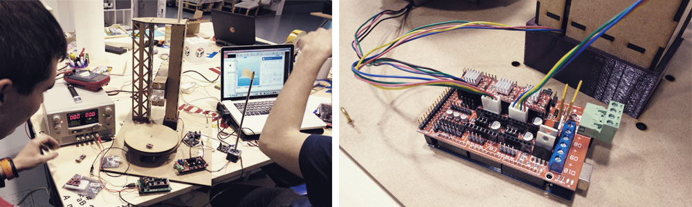
Once we had all the pololus motor driver regulated, we checked by a small test that all the motors worked individually and then we connected all of them to the ramp plate. After this, we downloaded an example program to use with ramps for working with 3D printers. We cleaned everything that does not correspond with the motors leaving just the movements code. Before loading the code, we put the machine in a safe position so we have time to turn it off if something goes wrong...
Once the machine was placed in a safe position, we uploaded the program to the Arduino and observed how the motors began to move together.
After this, we programmed a series of movements for the functions that we wanted to do and we uploaded the code again. We tried with the first head that we did, and we could test that it doesn't work with foam, but it works with clay instead.
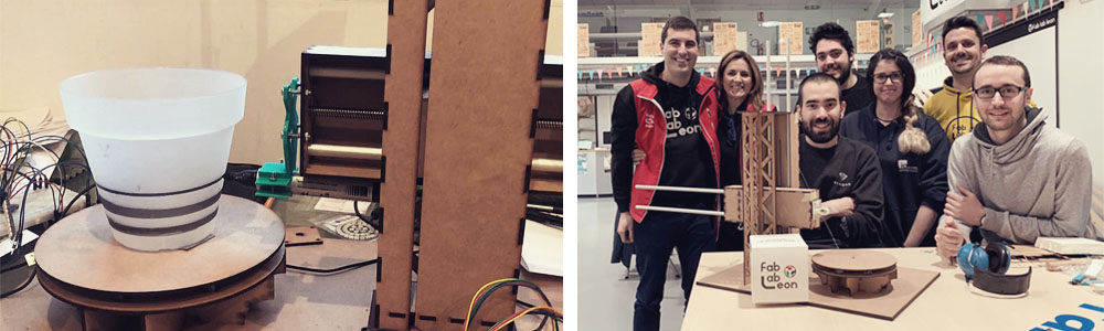
Then, we decided to try with a marker as we discovered that our machine worked better as a "cylindrical drawing machine" rather than as a "vertical lathe".
And this is the code that we used to make these initial movements:
Programming 2.0
We continued working on the code and we did a second version in where we are able to control each axis independently. We controlled the movements of each axis depending on the number of micro-steps, which corresponds with a distance.
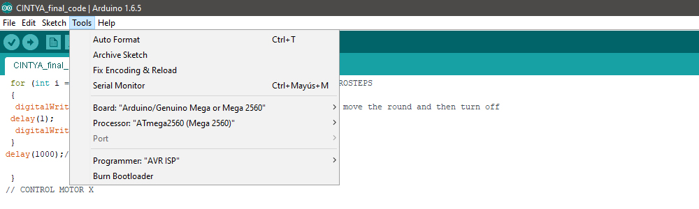
To send te code from Arduino IDE we used this settings:
And here is the full code, that we explain below:
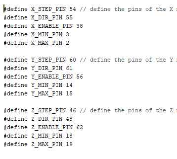
Arduino ramps' pins
In this part of the code, we are setting the pin numbers of the ramps for Arduino.
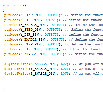
Variables and initial position
In this part of the code, first, we are telling Arduino that the motors are outputs. Each motor es defined by the number of micro-steps, the direction (hight=up, low=down) and if the motor is enabled (hight) or disabled (low). Then we set that at the beginning all motors are disabled (low).
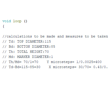
Calculations
In this part of the code, we explain that we have calculated that 1 turn of the motor is 3200 micro-steeps that means 8mm. (so 1mm. = 400 micro-steps). Depending on the geometry that your cylindrical object has, you have to calculate how much the motor needs to move.
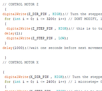
Axis's movements
In this part of the code, we are configuring the movements of each axis, which you can control independently. And we control them based on the micro-steps that you want that the motor does.
To know more information about the design please visit Alejandro Ulecia's webpage.
And finally, here you can see the machine working customizing a plant pot:
Files
Please find below the completed set of files that we used to make the CINTYA machine: Machine Leon 2019 _ CINTYA: the cylindrical drawing machine.

Special thanks to Nuria Robles, Adrian Torres y Pablo Nuñez.