
Week 06. 3D Scanning and printing
20.02.19 Class
In this class we gave everything related to 3D printers and we had the opportunity for a member of stratasys to give us a talk about the importance of design thinking about manufacturing later using additive manufacturing.
Week planification
This week, it’s a different touch-up, but I’m more used to it and it’s already on our site. He planned the week for me in the following way:
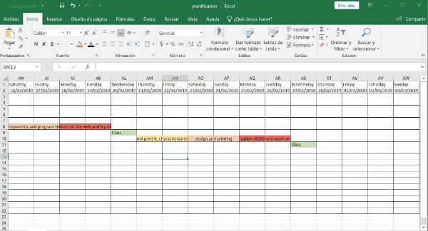
Thursday and Friday I will do the 3D scanner part because, to do this part, I need to move to the fablab of the European University of Madrid where my fabacademy colleague, German works. Once I have finished this part on Friday I will also use it to characterize the machine that I have in my house and try to launch the scanned part in my printer.
Saturday and Sunday I want to use them in the design of the piece and launch it to 3D printing for Monday to get an idea of the dimensions it has, since this piece that prints will be part of my final project.
On Monday and Tuesday I will characterize the big fablab machine and I will also work on the old website and on the new one to develop a little more and ordering the information that I have been uploading throughout this time.
Group assignment
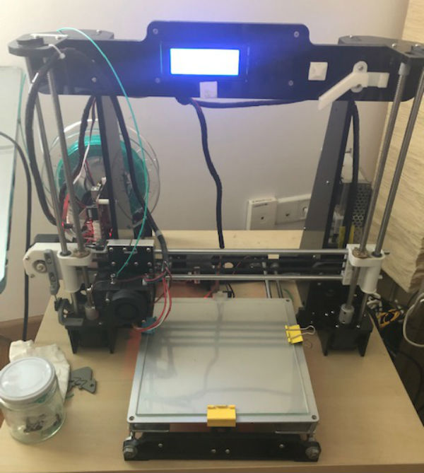
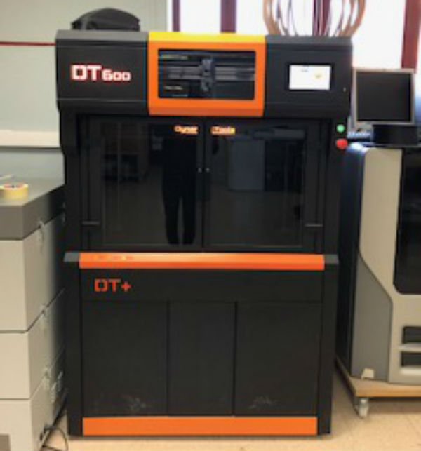
In this part of the weekly assignment I will characterize two different machines. The first one is going to be the machine that I have at home, the anet a8, a 3D printer of medium size and very cheap to obtain. The second, is going to be the biggest machine we have in the fablab, the Dynamic tools DT 600, with large dimensions of printing and manufactured in Spain.
In addition, the difference between these two machines is also in the nozzle of the extruder thereof, since one is 0.4 mm. And the other has a 1 mm nozzle. Diameter.
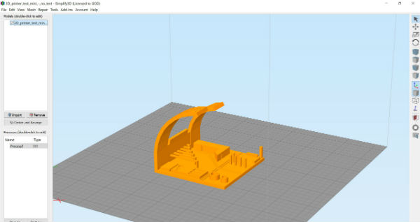
We will compare the qualities of these using the g-code processing program, simplify 3D, since it is the fablab’s sponsor and writing down the parameters used for each printer used.
ANET A8
TEST 1.
Parameters:
Layer height: 0.3 mm
Top/bottom solid layers: 3
Perimeter shells: 2
Infill: Rectilinear 20%
Bed temperature: 60ºC
Nozzle temperature: 200ºC
TEST 2.
Parameters:
Layer height: 0.2 mm
Top/bottom solid layers: 3
Perimeter shells: 2
Infill: Rectilinear 20%
Bed temperature: 60ºC
Nozzle temperature: 200ºC
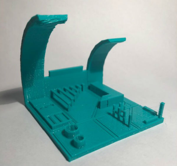
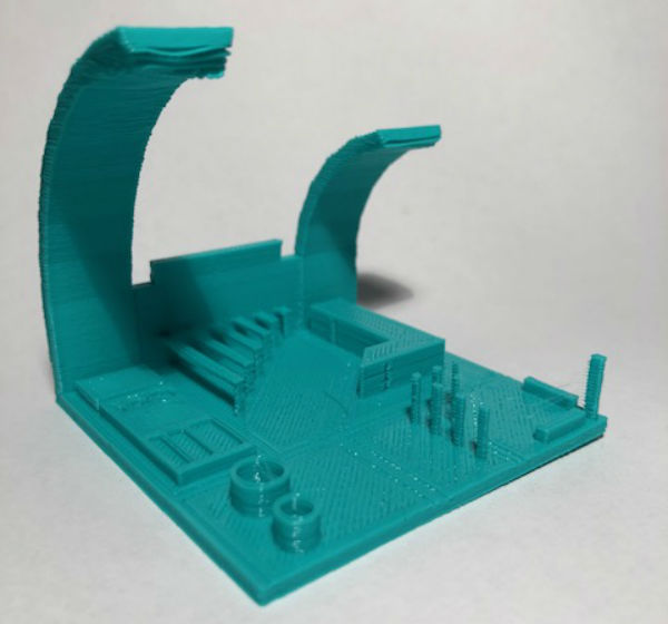
You can see the difference between the drop off in a print at 0.3 and 0.2 layer height. As we decrease the layer height we get a higher quality.
DYNAMIC TOOLS DT600
TEST 1.
Parameters:
Layer height: 0.5 mm
Top/bottom solid layers: 3
Perimeter shells: 2
Infill: Rectilinear 20%
Bed temperature: 40ºC
Nozzle temperature: 210ºC
TEST 2.
Parameters:
Layer height: 0.4 mm
Top/bottom solid layers: 3
Perimeter shells: 2
Infill: Rectilinear 20%
Bed temperature: 40ºC
Nozzle temperature: 210ºC
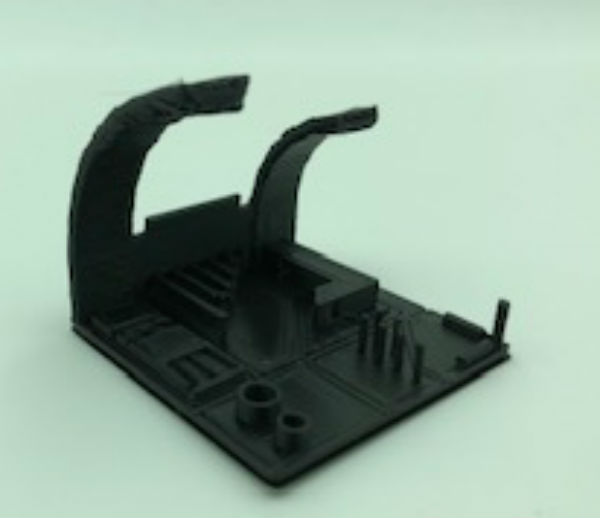
It can be observed as in the first impression the filament picks up more in the parts with more angle and in the second this phenomenon improves considerably.
Individual assignment
Design and 3D printing
For this part of the assignment I have decided to work on one of my two pieces of the final project. I have decided to retouch my backlight design according to the proximity sensors that I have been looking to place in ellar and the RGB led matrix that I also want to incorporate.
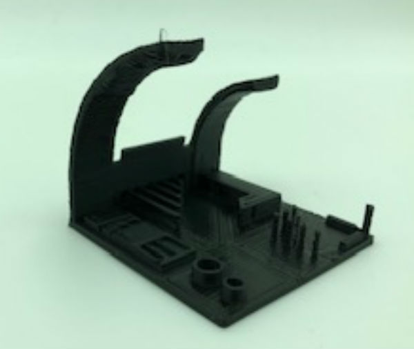
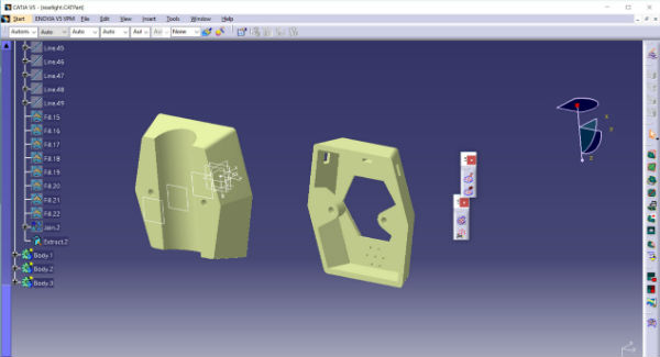
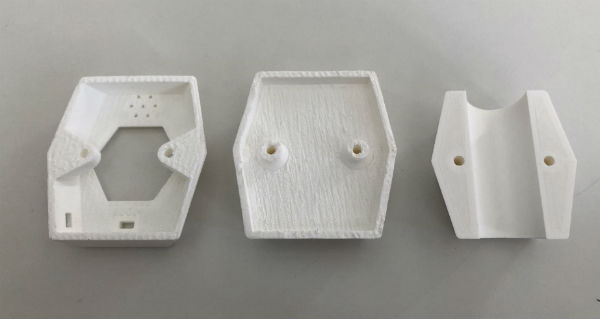
I've made the design in Catia. It consists of three parts, the first two connect the light to the bar of the chair and the third part supports the LED array and also closes the entire part of the electronics. the three parts are closed with two screws which have in the part of the external electronics some nuts housed in this cover to get the complete pack closed.
In the image of the design you can only see two parts where the electronics will be housed, but in the image of the manufactured parts you can see the three-piece pack with which the complete package will be made.
This piece can only be manufactured with 3D and not in a subtractive way since it has inside the housings for the nuts that will serve to make the enclosure of the complete package.
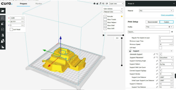
For the group assignment tests I used Simplify program, because with the Dynamic tools printer it is the only one I can use and therefore I have used this on both printers. For the printing of my pieces in the individual assignment I have used Cura and in this way I have been able to use two different programs and work with two very similar programs but with different interfaces.
With this design I have released the three parts that make up this piece and in this way I can get an idea of how my final piece is going to be and I can go adjusting it to adjust it to the characteristics and dimensions of the rest of the elements.
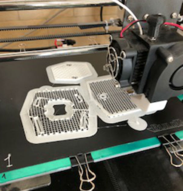
Step by step I am getting closer to the main idea that I want from my final project, over the next few weeks I will launch to print the pieces that make up the front focus and I can also get an idea of the shape of it.
3D scan and 3D printing
In this part of the assignment, I had to approach the fablab of my German partner in the European university, since the scanner of our fablab is in maintenance and is not operational. In this way I have met the rest of the fabacademy colleagues that we are doing remotely in collaboration with the fablab of León.
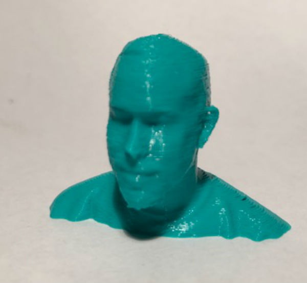
In this part each of us has scanned the head of the partner and we have printed our own head.
We have used the scaner sense and the 3D systems sense program.
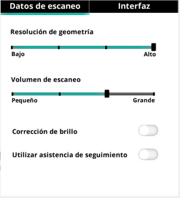
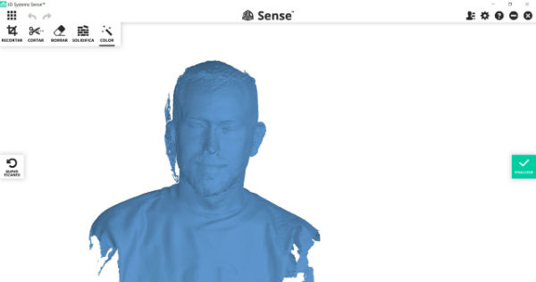
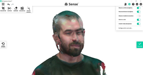
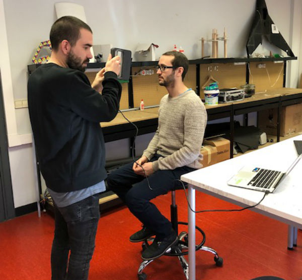
Also, with the program of this scanner, I have cleaned the work done and I have done it solid so I can export it later in stl. In my case I have printed the model with the A8 Anet that I have at home.
My files
Print test STL
My head STL
Part 1 final project STL
Part 2 final project STL
Part 3 final project STL
Conclusions
The assignment this week has been much more bearable than last week and I have been able to finish it with time, which has been very important for me since I have been able to focus on organizing the web, add things that I needed to add and also I have been able to continue working on the new website.