
Week 12. Output devices
03.04.19 Class
After the week of inputs touches the week of outputs, the first thing that Neil explains is the sources of power and batteries and the dangers that these can entail. After this, it begins to explain the different existing outputs such as led, RGB led, LCD screens, speakers, motors, servomotors, stepper motors, brushless motors, also explains the motor controllers.
Finally, he explains both the group assignment and the individual assignment that we have to carry out for this week.
Week planification
This week I have planned it in the following way according to my planning excel:
Group assignment
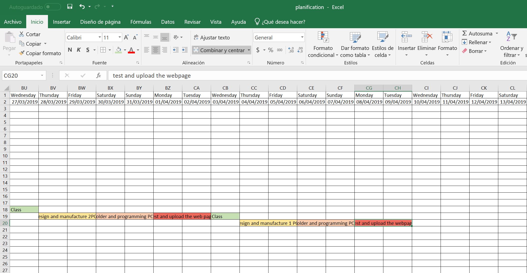
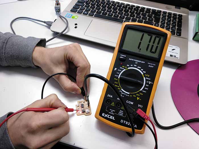
The group assignment this week is about measuring the voltage, for this I have used together with my classmates the hello board that we did previously. This time we have loaded the button program to leave the LED on continuously and measure the voltage that reached it.
We have measured both the voltage of the microprocessor to the resistance, which approached the 5V that should supply the plate and we have also measured the voltage after the drop in resistance and that actually reaches the led, which does not reach 2V. In this way we have learned to measure and know how to locate the different voltages that we can find in the electronic boards that we have.
Individual assignment
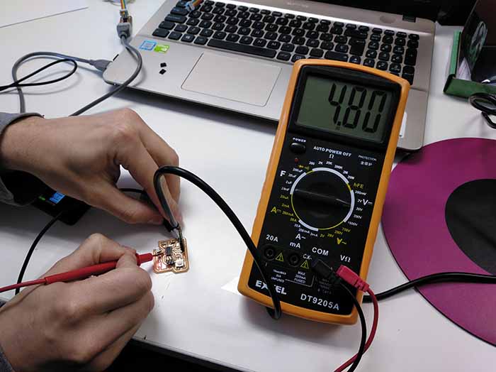
As an individual assignment I have proposed to create a circular array of neopixel which I can use for my final project of the light of the bicycle.
To make this new plate, which does not exist in any other assignment or in the page of the fabacademy, I had to make a replica of the plate used for other types of outputs and try to adapt it to connect my neopixel array. For the Neopixel, the only thing I will need is a digital signal, power and ground, therefore, any plate that is of this type is useful. To make the neopixel array I will use the following neopixel:
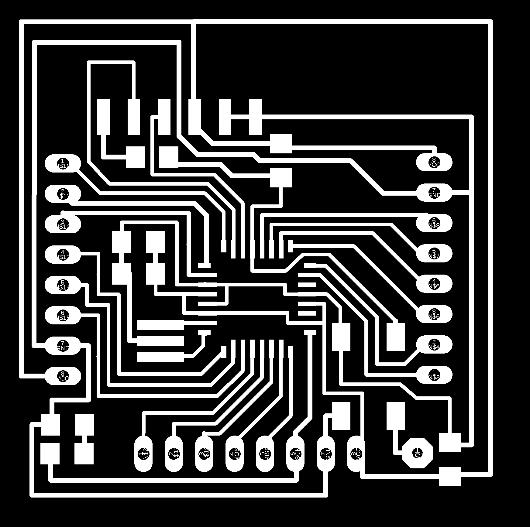
 I start preparing the main board in Eagle where I'm going to put my attiny 44, my ftdi cable, the connectors for the bus communication and the flat cable to connect it to the programmer.
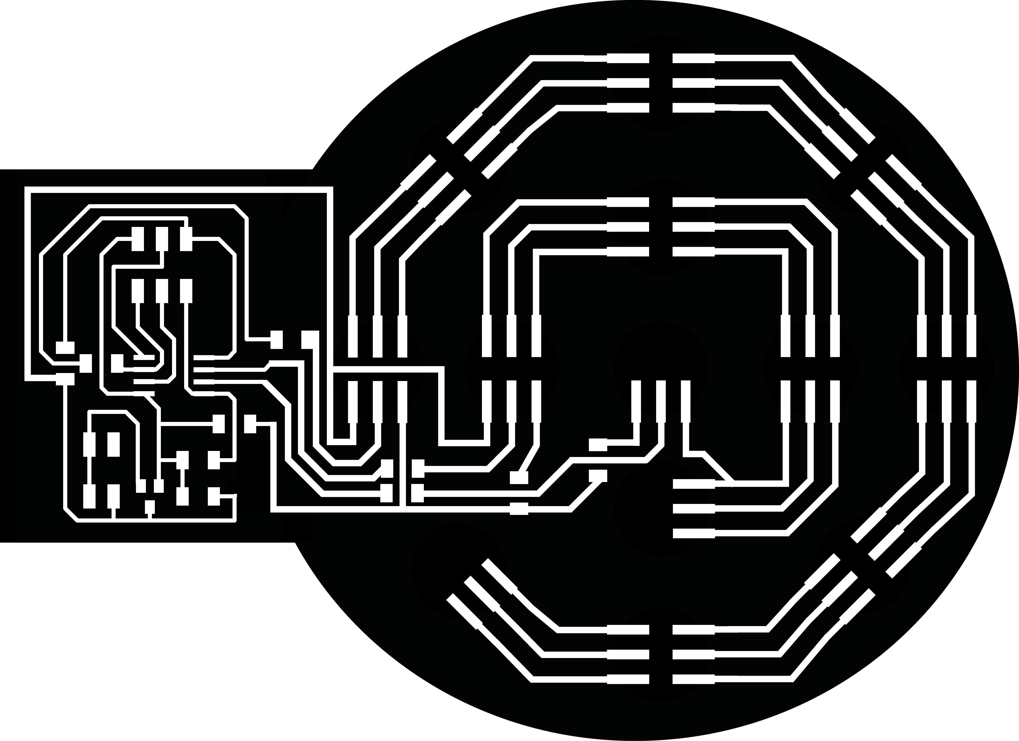
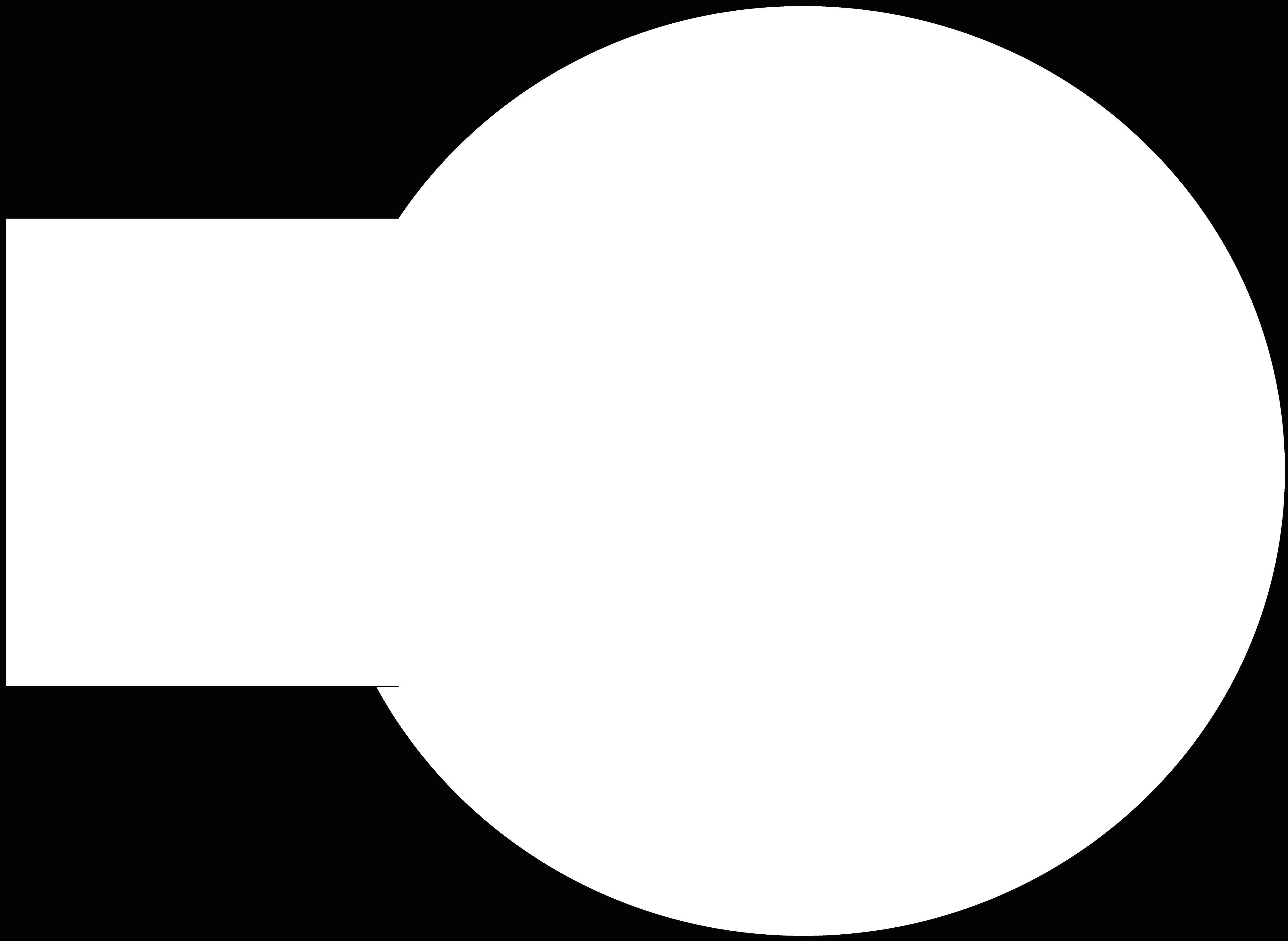
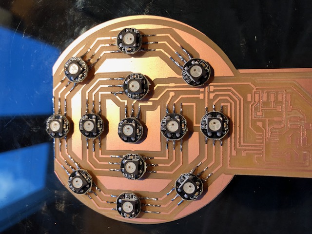
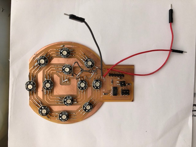
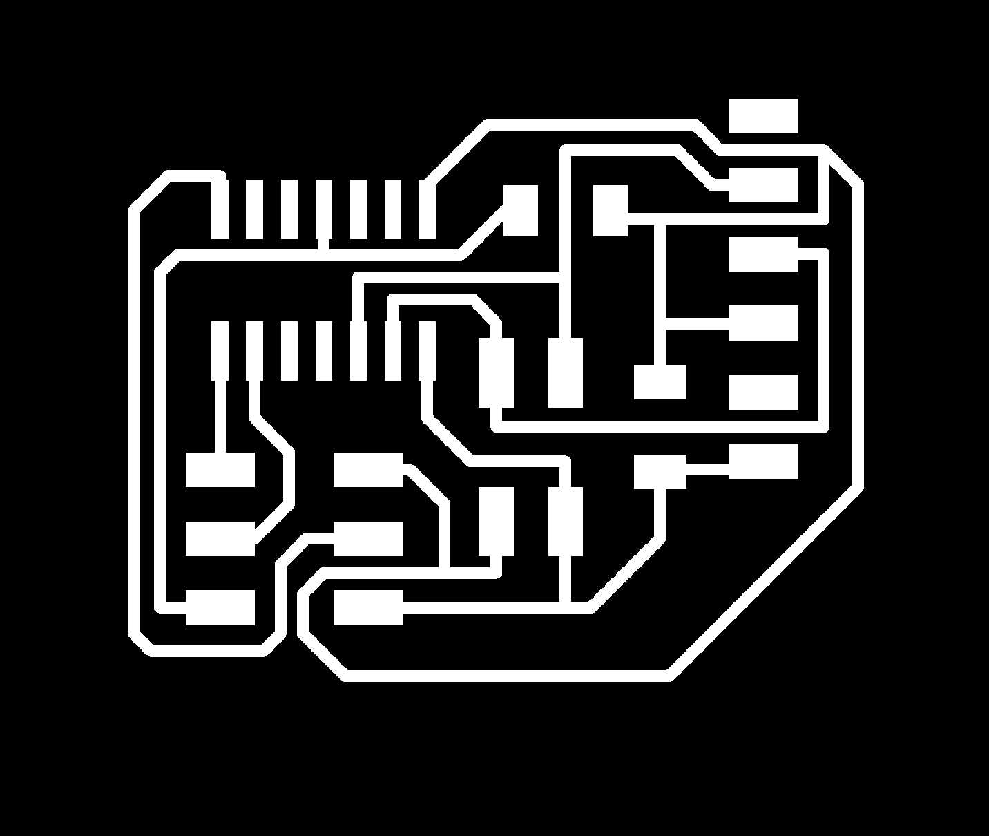 With this base created, as in Eagle I do not have the traces or the element of this type of neopixel, I decide to create the array using the Adobe Illustrator program, I take measurements of the neopixel that I have obtained and I start to design the plate in a way "Manual" from this program. Next, I show the result that I am going to use to mill the plate that I am going to use to solder my components.
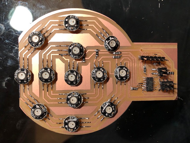
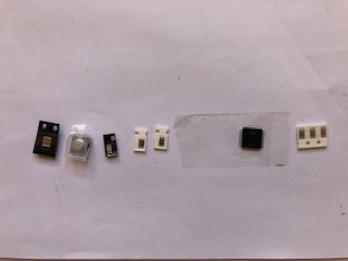
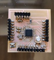
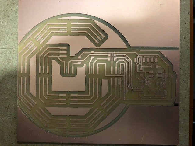 On this plate I start to weld the components that I am going to use, which are the following:
1x Attiny44
1x AVRISPSMD
1x 1X06SMD (FTDI)
13x Neopixel
2x 500kΩ resistance
1x 1000kΩ resistance
1x 1µF capacitor
1x 4 pin conn.
 Once all welded, I download the following adafruit library for Arduino and neopixel: Adafruit neopixel library
I charge in Arduino and try to upload it to my Attiny 44 board and it does not work, the problems start. I quickly ask colleagues for an internal forum and they tell me that the problem I'm going to have is that the library occupies more than what I can have memorized the micro attiny 44 that I have soldered on my badge. Therefore the replica of my board to get another one from another output for my array of LEDs does not work.
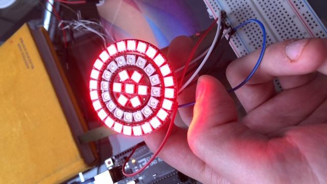
What interests me most at this moment is to know if my neopixel work and know how to program this type of LED since it is one of the fundamental parts of my final project. For this reason I have also bought an array of circular LEDs and it is with this that I have been testing the programs that I have been doing using Arduino.
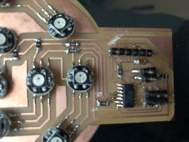
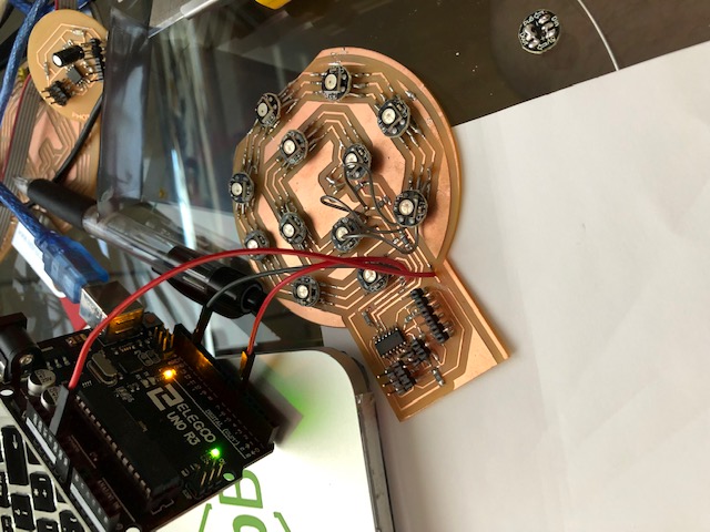
Seeing that these programs work in the normal array I decide to make a "Frankenstein" with my board and join different tracks and I have cut others to get that connecting to this my Arduino to be able to prove that the neopixel that I have set work.
With this "Frankenstein mounted, I have connected it to my Arduino, I have changed in the program the number of neopixel that I have and I have uploaded it to see if my neopixel works.
Surprisingly 4 of them have worked perfectly, but the rest have run out.
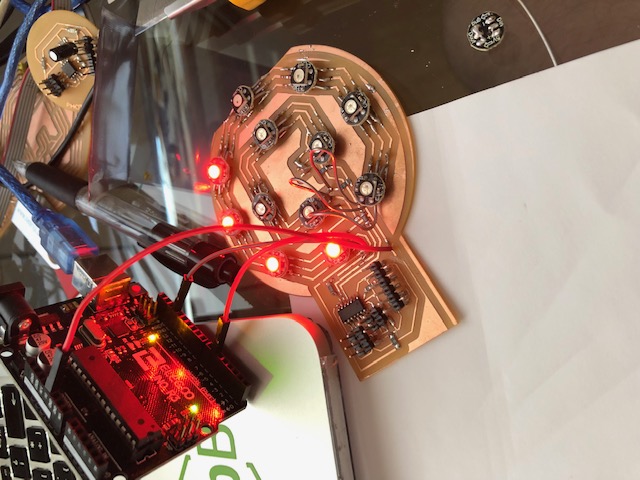
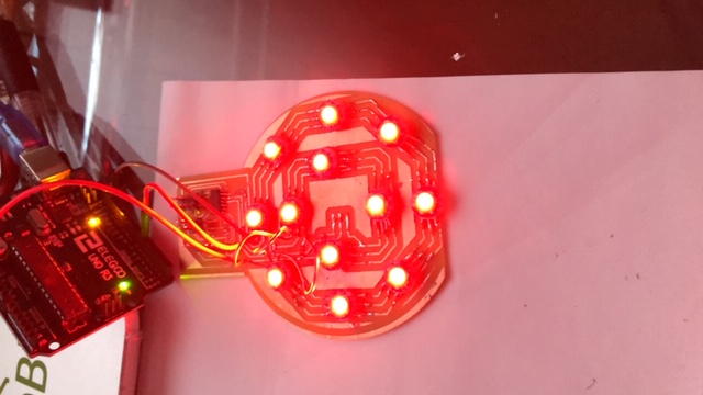
After checking all the connections between the neopixels with the voltmeter, I discovered that I had a cold solder in the first neopixel that stopped working and therefore did not let the current flow to the rest of the neopixel. I solved this and I have uploaded the program again. At last all the neopixels have worked for me. Next, I show a photo.
After this great work and seeing that this assignment I need for my final project, I decide to continue with this project and build a fabkit 0.4 to be able to connect my neopixel array to it and be able to program it and make it work. To make the fabkit I have based on the following web page: Fabkit 0.4
I have had to make several modifications based on this board since I had to reduce most of the tracks and also other of them I had to separate them from each other through the eagle program. Below I show my boards and my modifications are downloadable in files.

After designing it, I have milled and soldered all its components (these components appear on the fabkit page).
I programmed it as indicated on the website and I tried to upload a blink example program. I have checked that it works and I have connected my neopixel array to my fabkit 0.4.
I upload the program that I used for my previous tests. I modify the number of neopixels I use and the digital pin through which I will enter the data. WORKS! therefore it is the plate that I will use for my final project. Neopixel array will have to improve and debug a little more. In the following video you can see how the set works.
My files
Neopixel program
Fabkit 0.4 board
Fabkit 0.4 schematic
Conclusions
It has been a busy week for the trip but I think that throughout the fabacademy we are going to learn a lot about programming and I am looking forward to using sensors. After many weeks and being very busy, I was able to finish the assignment and also advance in my final project.