5. Electronics production
This week I have been very very entertained with those things I have never seen before, the precision milling and electronic circuits.
Learning the machine
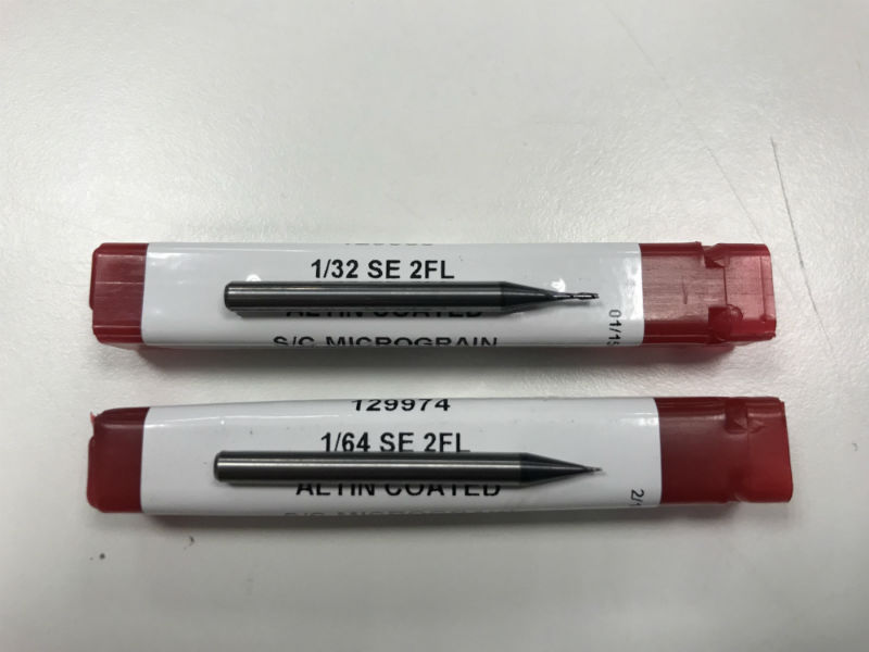
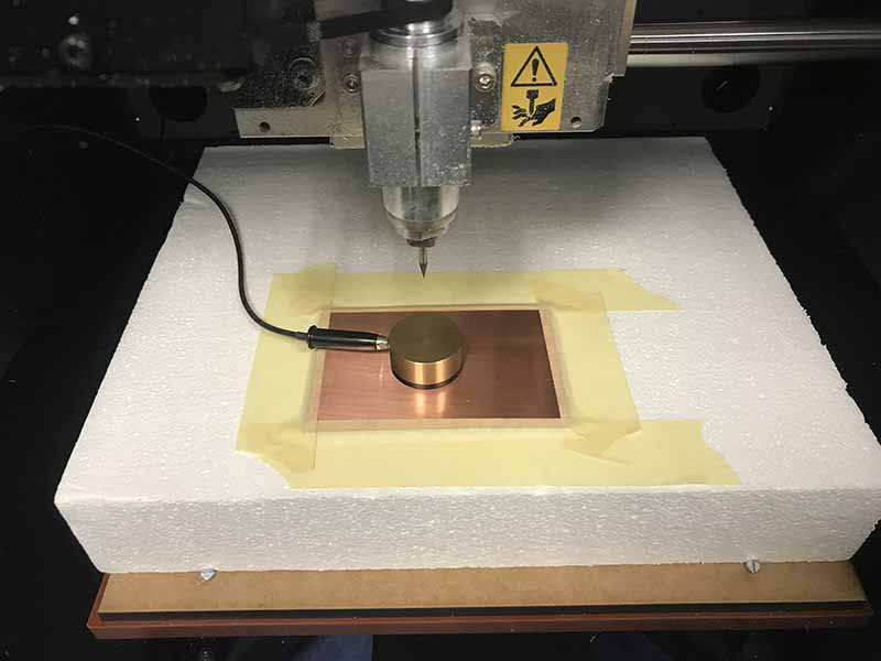
It´s true that I have milling before, but in big scale CNC Machines, with big mills and cutting wood planks and so. But when I saw those little mills I have to confess that I started to laugh. This are the mills I used and below the links where you can buy it.
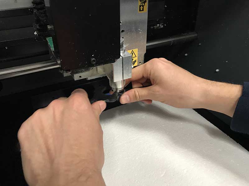
After that, I opened the machine, in this case a Roland MDX 40, and I tried to change the mills. I know how to do it in the biggest one, and it is the same in that little milling machine. You just will need two spanners.
FabModules, the great discover!
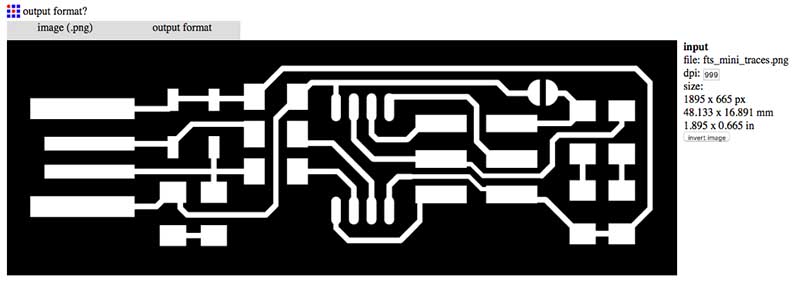
As we know, there is a big difference between a bitmaps picture and a vectorial document. In all programs I use to design, I always use vectorial and 3D modeling programs because it contains mathematical information you can share with machines to generate whatever you want. But now I have discovered one new fantastic tool. FabModules allows you convert one (black and white).png picture to generate the paths to send to the machine.
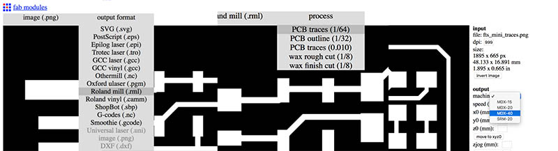
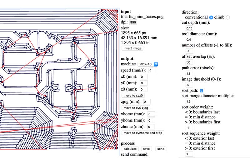
Here is how it works. First select your .PNG picture. Second, it will be appears a new tab, with the output format in this case roland .rml. Finally the type of mill, the inner traces or the out traces.
Now select your roland model my case it is a MDX40A as I have said before. The parameters should be like this, after testing many times!! It´s important to change to 0 X,Y,Z origin; 2 Zjog; and the depth of the cutting 0.15 will be enough; if you want to mill all the surface, change to -1 the offsets. You could also chage the overlap but less than 50% will be slower.
- Tip! If you change to 1 sort sequence weight you can control the size in your copper board and check if cut everything or it has unevenness.
Let´s start milling
The software we used to comunicate with the milling machine is Vpanel you can download for free here:
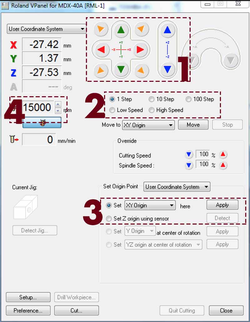
- 1 The Movement panel to control the head of the mill.
- 2 The Speed of the mill when you moves it to aproach to the origin fo the cutting.
- 3 Here we use both first options; To fix XY origin point of the model in the board machine.
To detect the metal sensor of Z Axes - 4 To control the speed revolutions of the mill.
Thats all what you need to control your machine and generate the cutting.
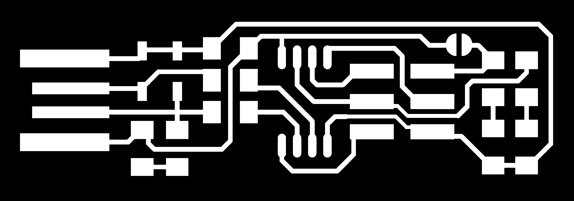
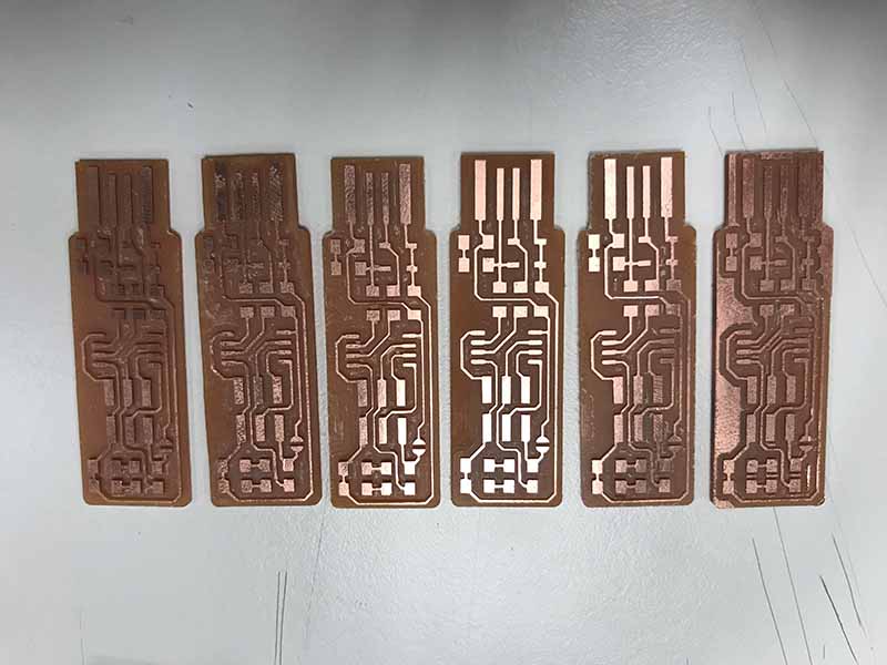
Now we can mill the copper planks to create our FabTTiny ISP. This is the other complicate part, because as I have said before, the mills are really smaller and you have to be careful with the options you send to the machine in the FabModuls.
I want to enumerate the copper planks, and also say that I use FR1
  FR1 - the softest one copper with paper pulp
  FR2 - soft but less that FR1, copper with paper pulp
  FR3 - Medium soft, copper with resin
  FR4 - Most common, copper with glass fiber resin
First test
As you can see in the picture below, the parameters are not correct in the first try. And there is one problem more, the calibration in a soft surface, in this case expanded polystyrene, that made irregular cuts in the surface.
Another thing to consider is the calibration in every point of where you are going to mill. For that reason in the program you have to chose Set Z Origin using sensor put the piece down the mill and wait.
After a few test more, I have found other problem. Zjog has 0 number and I need to change by 2 in this case, because when the milling machine finish the first path to start the new one, it does not up the mill so it cut everything when it cross the circuits.
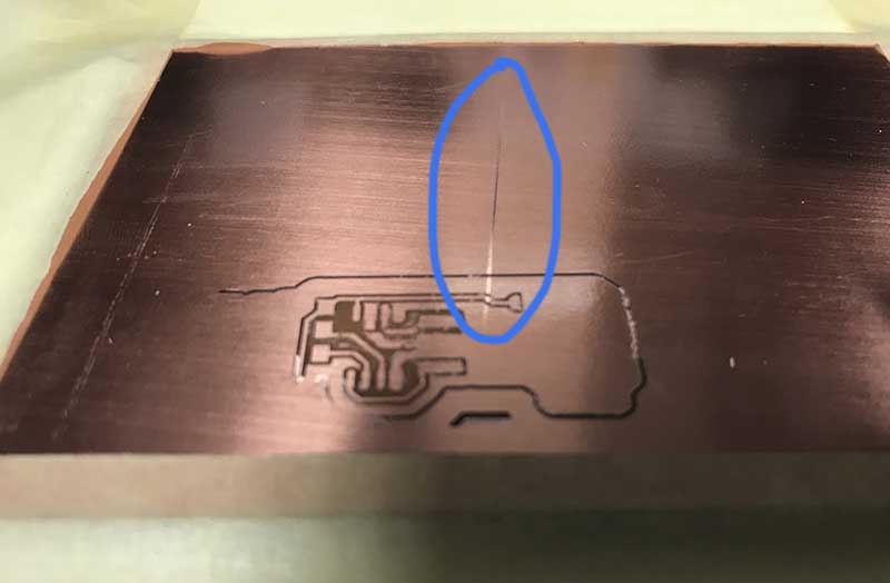
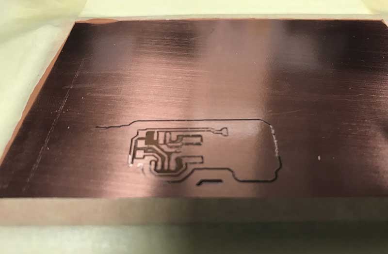
When I achieve my first complete milling I could see that the cut wasn’t as clean and defined as I would like it! I solve that issue when I changed the climb option for conventional option. Now you can see here the difference in the edges of the milling. It took me 3 hours of practicing.
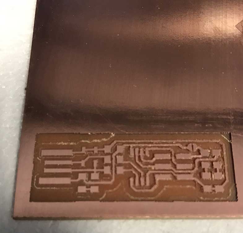
Finally I could mill at least all this PCB as you can see with the correct parameters
You can also download my configuration in FabModuls here:
Assembling FabIsp
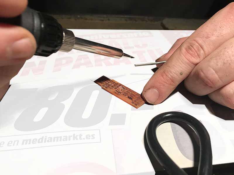
This is my first time soldering components in a PCB. Also you have to notice that the component are really smaller, so it has been very difficult to me this assignment because you should know a lot of things after that assignment like the polarity of the components, soldering of course, some Tips as use Flux with stain to solder it easy, etc.
Here is the list of components you will need:
1x ATtiny45 or ATtiny85
2x 1kΩ resistors
2x 499Ω resistors
2x 49Ω resistors
2x 3.3v zener diodes
1x red LED
1x green LED
1x 100nF capacitor
1x 2x3 pin header
In my first class of soldering, my father taught me how to take the solder, how to manage the stain, and the patience you will need to achieve this assignment correctly! For that reason, I did one test (incomplete) FabIsp just to try how to solder, that you can see below.
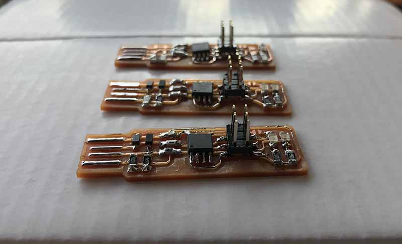
Now all you can imagine about assemble this components to the PCB is false! It is not as easy as you could see in online tutorials, and you have to practice a lot. Finally I achieve to solder the second FabIsp I did in 1 hour.
But I have to confess that I now, instead of my basic knowledge and low practice I find solder, as relaxing as make Sudokus!
Programing FabIsp, more diversion!
It´s a good idea to take the polymer and check if you have soldered the components correctly.
Now I started to program and show it our FabTTiny is well done!
The beginnings haven´t been easy!! Everything does not work, you don´t know what are you doing, you start thinking if you have taken a good decision or maybe you can live in your little but safe and comfortable bubble.
I work on Mac Os, so I had to download and instal this package and the base firmware of your FabIsp:
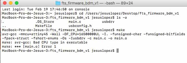
Open the Terminal and type ” cd “ and drag the file of the firmware. The result will be something like this:
MacBook-Pro-de-Jesus-3:fts_firmware_bdm_v1 jesuslopez$
Now type make
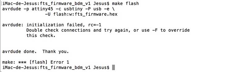
The first step was my first wall, my first problem and my desire to drop out the FabAcademy. 3 hours later I was still crying with this message.
Finally I couldn´t fix the mistake, but I imagined that my computer has an old software, Sierra 10.12.6. When I have tried repeat the same steps in a Sierra 10.13.6 and in this case it worked.
In Mac Os you will have installed also this package:
Now it is turn to connect the original fabIsp and your copy like this:
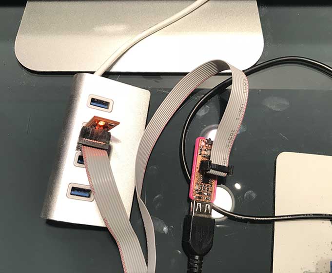
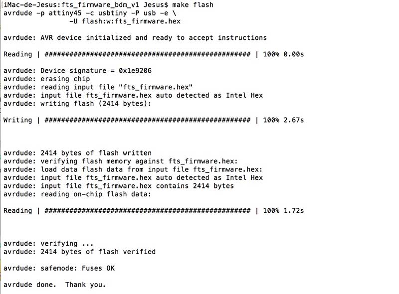
Then in the terminal, type make flash When you achieve this, another problem appears…
This problem was a mistake in the way I connected the wires in the pines, when I corrected this I could continue:
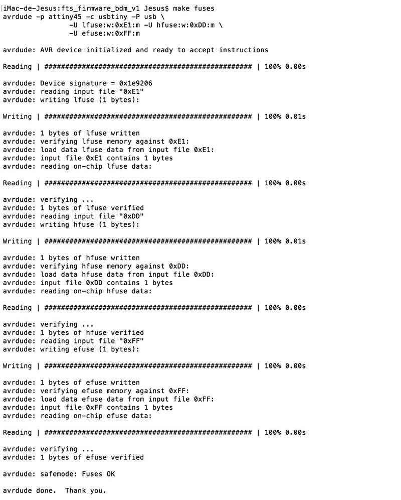
When the operation finishes, type make fuses and let terminal works.
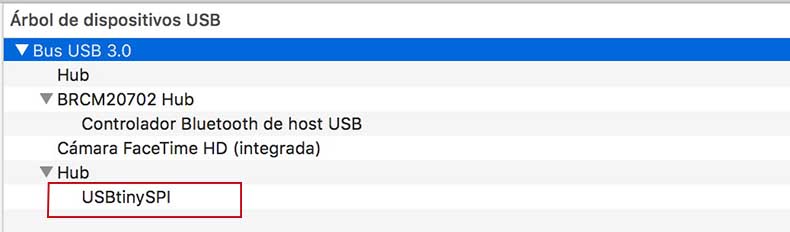
Then you are a super master of programming !! Of course you are not… but if it is your first time programming maybe you fell so. Now disconnect both usb and connect only yours and test if computer recognize it:
At the end, connect again both usbTinys and type this command in terminal make rstdisbl
Just remove the jumper to prevent overwriting in your USBTinyISP.
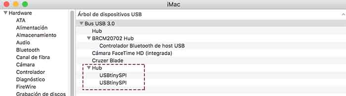
And here you can see both USBTiny working at the same time!
I want to recommend two pages of two students of FabAcademy, I have read to pass this assignment with my tutors too.

Este obra está bajo una licencia de Creative Commons Reconocimiento-NoComercial-CompartirIgual 4.0 Internacional.