_week 10
Molding and casting
Group assignment
This is a fun week, we are doing molds and casting them with different materials.
As a group assignment what we did was:
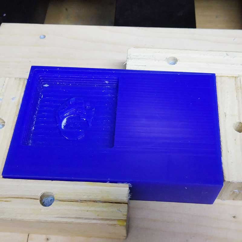
1_Create a 3D mold and mill it: we learnt how to use another type milling machine Roland MDX-40A that is similar to the Roland SRM20 we used for the MCU milling, and similar in some aspects to the Shopbot we used two weeks ago.
2_Review data sheets for each molding and casting material: For this assignment we used;
-Silicone OOMOO-25 to make the mold
(SMOOTH-ON this is a very good brand, easy to use, and hard to get any bubbles in the mold), on
their website they have a lot of resources, in the previous link you can find the data sheet of the
oomoo-25.
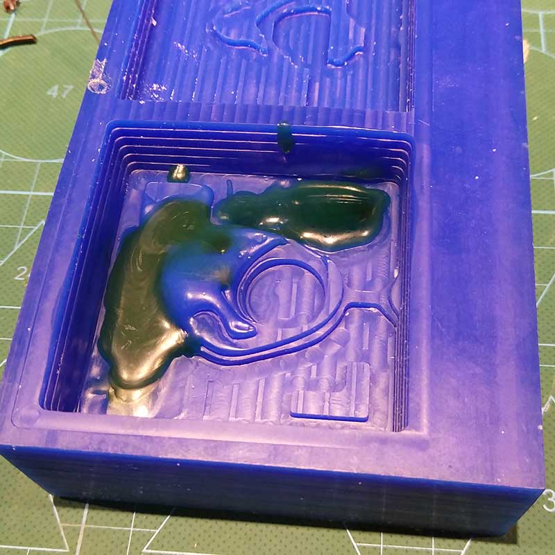
-XENCAST, fast cast polyurethane
casting resin , a type of resin to pour inside the molds. You can add pigments to
it (polyurethane colour pigments), also metal powders, just make sure to wear gloves...
-Dry stone, the usage
and aspect is similar to cast. In this case we used it as a casting material.
-Low Melt Fusible
Bismuth, this is an interesting metal that melts to a very low temperature, only
100 Celcius degrees, so it's super easy to heat with any home-made device and do some crazy tests.
We used it as a casting material.
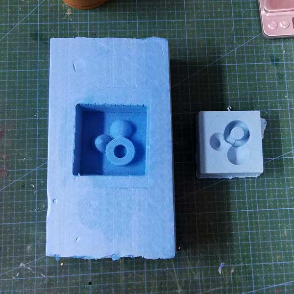
3_Make and compare test casts with each of them: using the mold we did in silicone and other
ice-cube molds, we did some tests using all the materials above. Oh forgot to mention the super cool
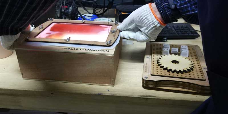
vacuum molding that we used as well to make some molds out of recycled HDPE plastic bottles.
For the complete information about our group assignment check out my classmate's website
Siyu
Here are some photos of our group assignment:
Individual assignment
So the task of this week was to design a 3D mold using the stock material provided (castable wax), mill it with the CNC machine and use it to cast parts.
It was a really cool week, I wish we had more than a week to develop this assignment, perhaps a two week
hands-on testing and experimenting other types of molds and castable materials... that would be
great!
In the meantime here's what I did this last days.
_INSPIRATION & IDEAS
Ok, so for me the first thing was to think what I was going to design for the mold, and what type of mold I was going to design (1 part mold, 2 parts mold or multiple parts mold).
As usual, I dug on the internet and found lots of ideas, but I narrowed it to what gave me more inputs to
work with.
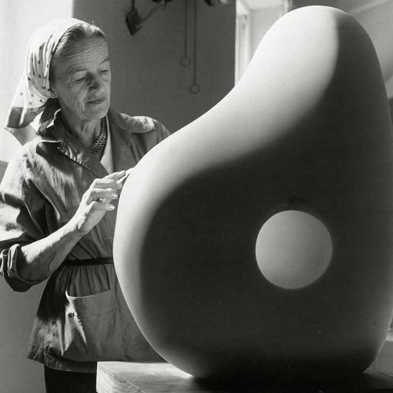
I knew I wanted to do something organic, with some curves and volume, like the sculptures from
Barbara Hepworth, that inspire me so much, but I also wanted to have color involved, like the
pigments that are sometimes added into pottery pieces that create this astonishing marble effect, and of
course I wanted all this to be a jewelry piece... a ring.
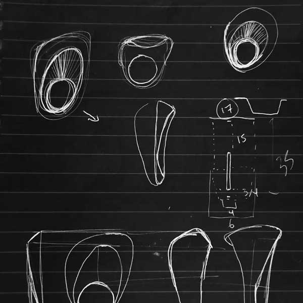
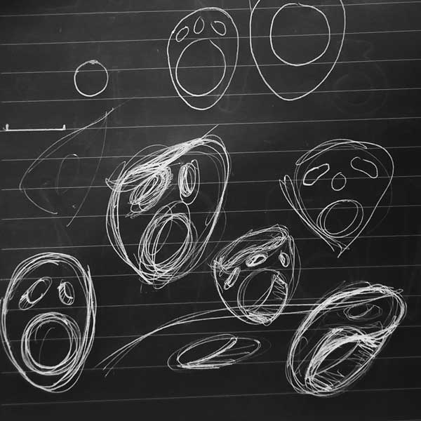
I did some sketches of the ideas I had in mind and some annotations of experiments I wanted to try during this assignment.
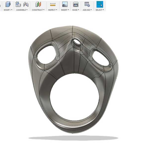
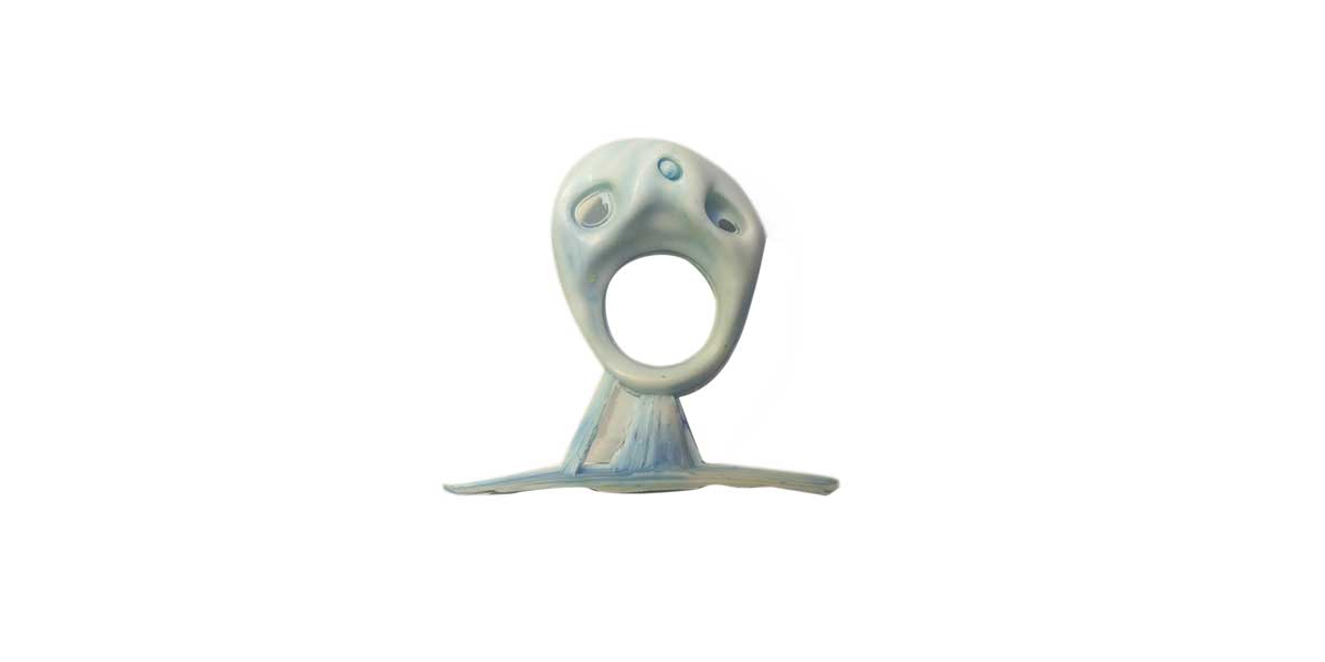
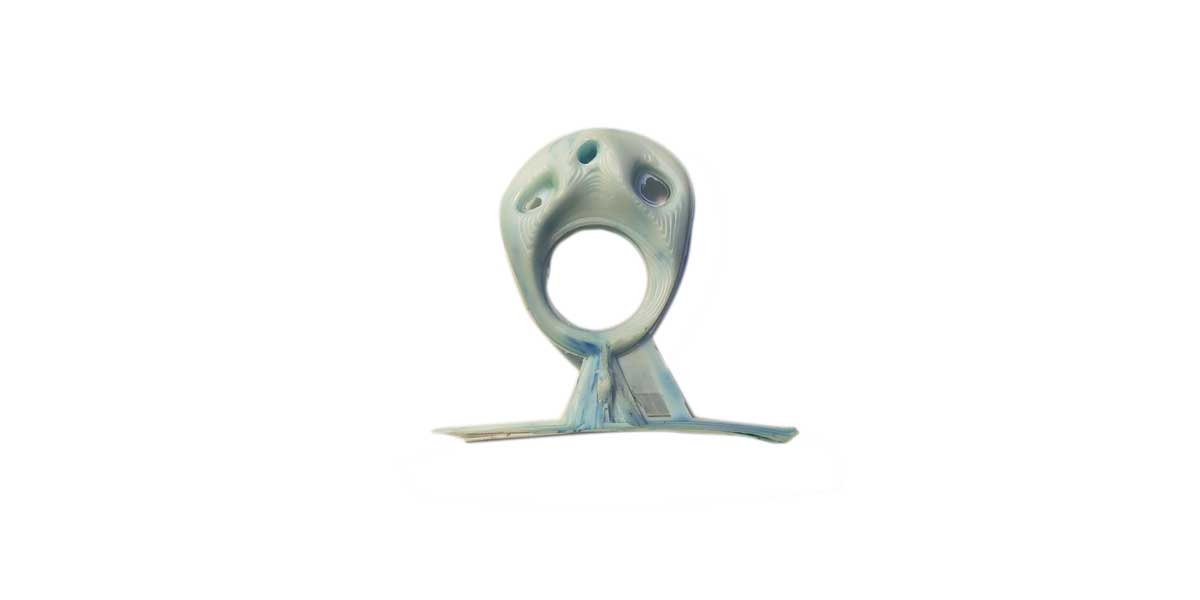
_3D MODEL OF THE RING
As I wanted to do some organic shape, doing it in Rhinoceros would be a it complex and would take some
time to do unless I used Grasshopper.
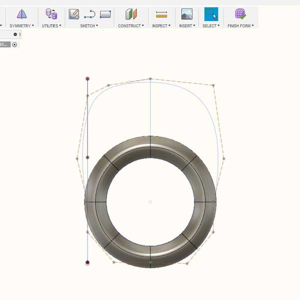
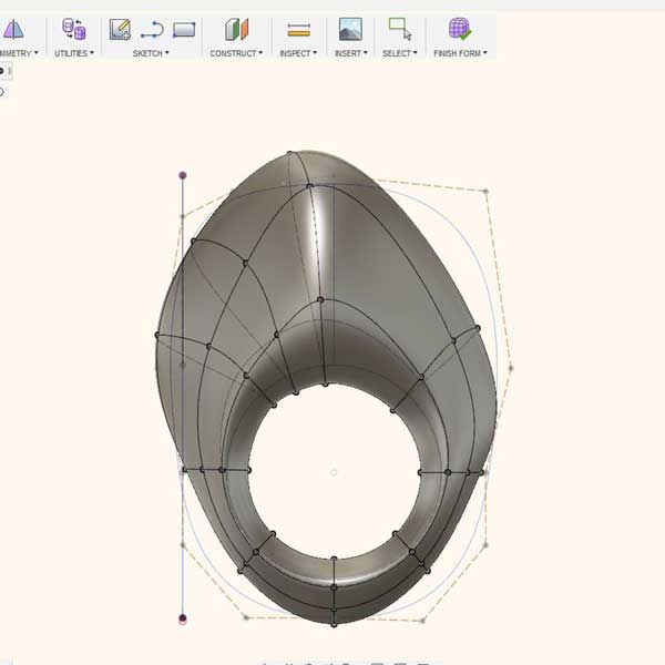
So I decided to use Fusion 360 but I used the function called sculpt, which allows you to
make organic shapes in a very freely way.
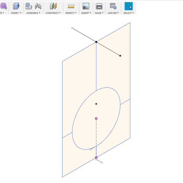
I first drew sort of a cage/box of the max and min sizes where my ring would be contained, this helped me
to have a reference for the sizes once I started using the sculpt mode.
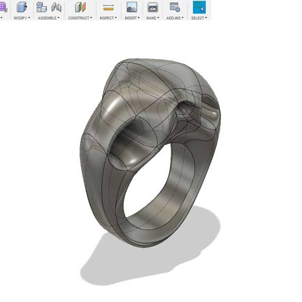
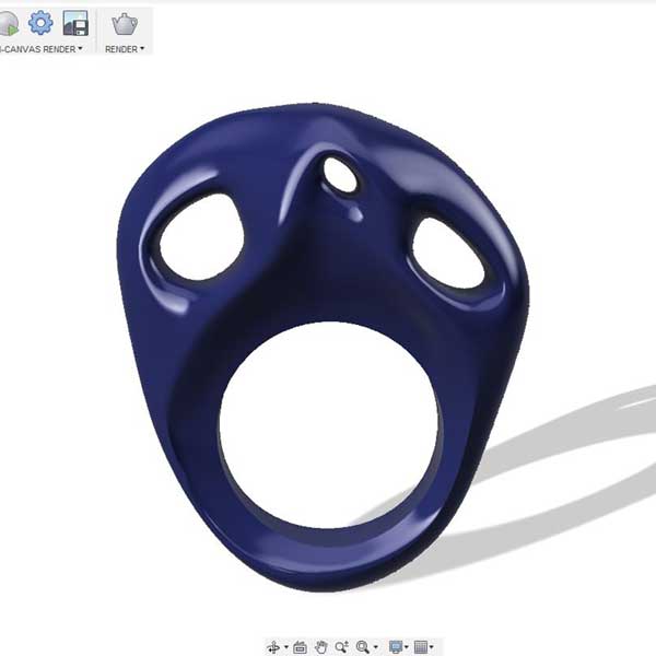
The origin shape I used to start was a taurus from there I started to deform the shape,
until I had something similar to what I had in mind, which in the end was a bit different but I liked
the outcome so I kept the shape I did.
Before doing the model, keep in mind the important notes I will write down below on section "TWO-PART MOLD DESIGN".
Sculpt mode is inside: CREATE- CREATE FORM
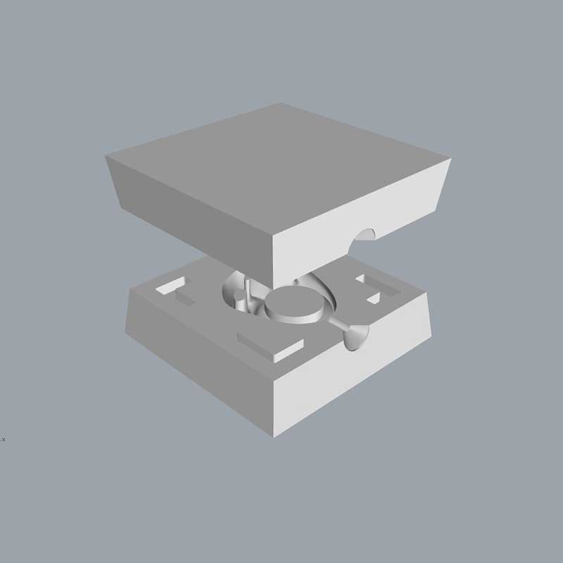
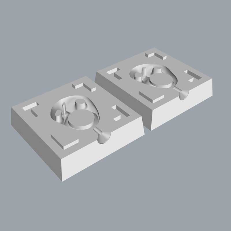
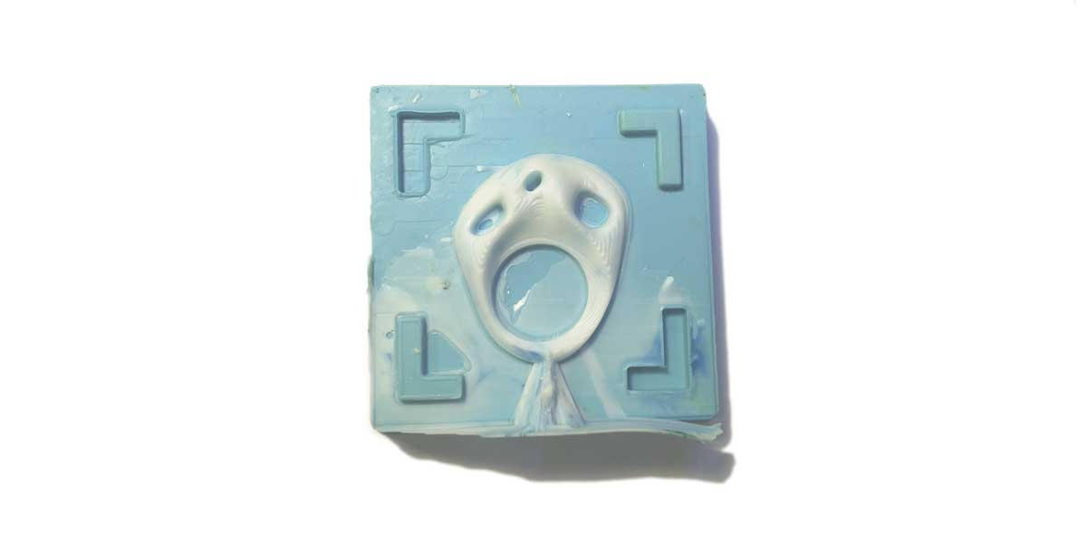
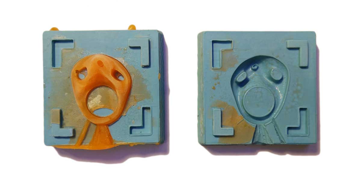
_TWO-PART MOLD DESIGN
Once I had the ring designed, I had to do what for me is the most important part of this assignment... the actual mold.
I decided to switch from software and I used Rhinoceros 3D to design the mold. So I exported my ring as .STEP and reopened it in Rhinos.
I decided I was going to do a two part mold, so for me this step of the assignment was
where I got more confusion and doubts, as you have to think the opposite, meaning, you are doing a mold
that is going to be the negative of your final piece, so during the process of doing the model I had to
assemble it to see if I was doing it correctly.
I advice you to do the same, whatever software you use, search for the assembly option to check that the
parts of your mold assemble or not.
***Some important notes about this step to keep in mind are:
1_MOLD STYLE, before designinig your model think if you are going to do a one side, two side or multi-part mold.
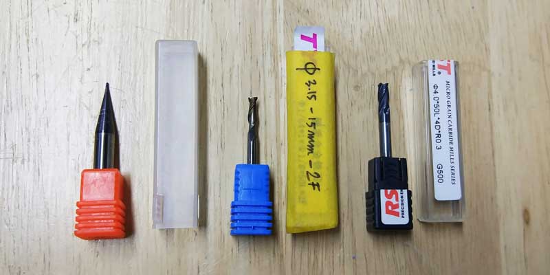
2_TOOLING, depending on the machine you are using keep in mind the endmills you have available, measure them and note down their sizes, as this are the key to design your model, and also the minimum sizes you can use for small details.
In my case I was going to use 3 types of endmills: two square endmills one of Ø 4mm, and one of
Ø 3mm for the roughing, plus one round ball endmill of Ø 1mm for the small details.
But as you can see from the photo the the shank on the smaller one is quite thick and the flute lenght
on all the three endmills has a certain lenght, so all this small details will affect when doing the
design of your model. Measure the endmills and keep in mind the minimum sizes you can use based on your
smallest endmill, and also keep in mind the depth the endmill can go without doing damage with the
shank.
3_UNDERCUTS, if you are doing a two side mold, keep in mind that you can't have undercuts.
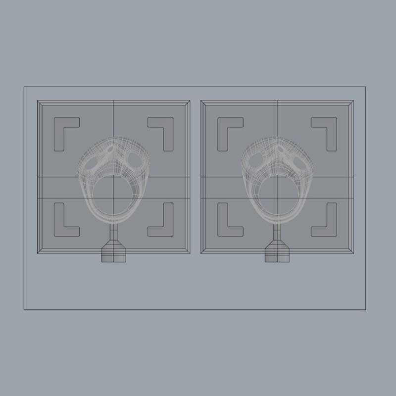
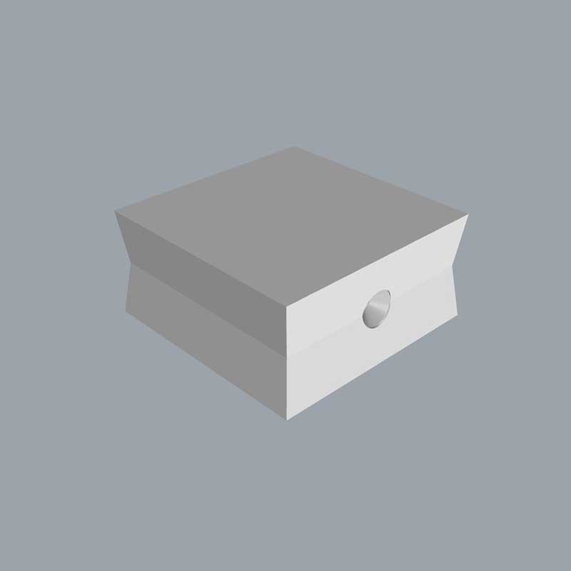
4_HOLE FOR CASTING, think well how and where to design the hole to inject your casting material, as this extra material will stay in your model and you need to clean it afterwards, so choose a place where this "scars" don't matter to be shown in.
As you can see on the example below if the hole were to be on top it would be more noticeable than the example in variation 2, as it seats below the ring in an area that is less noticeable.
5_MOLD WALLS Don't do straight the walls of your mold, give them some angle so it's easier to remove the mold once finished.
6_REGISTRATION KEYS, you will need them if you are doing a two or multiple parts model. It's safer if you use a combination of channel type and round registration keys.
TIP: make the male part slightly smaller than the female one (0.5mm or so), so that they can fit well.
Ok so once I had all the above clear I started building my wax mold keeping in mind all those contrains and tips.
Here are some photos of the process and assembly tests I did to see if all worked fine.
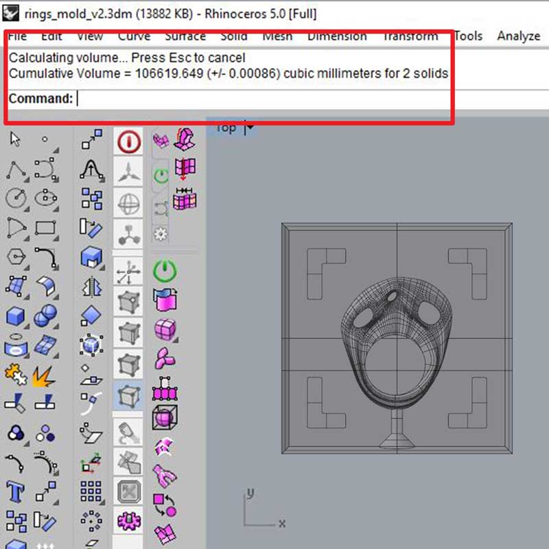
You can calculate the volume of your models in almost any 3D software, in Rhinoceros it is under: ANALYZE - MASS PROPERTIES - VOLUME.
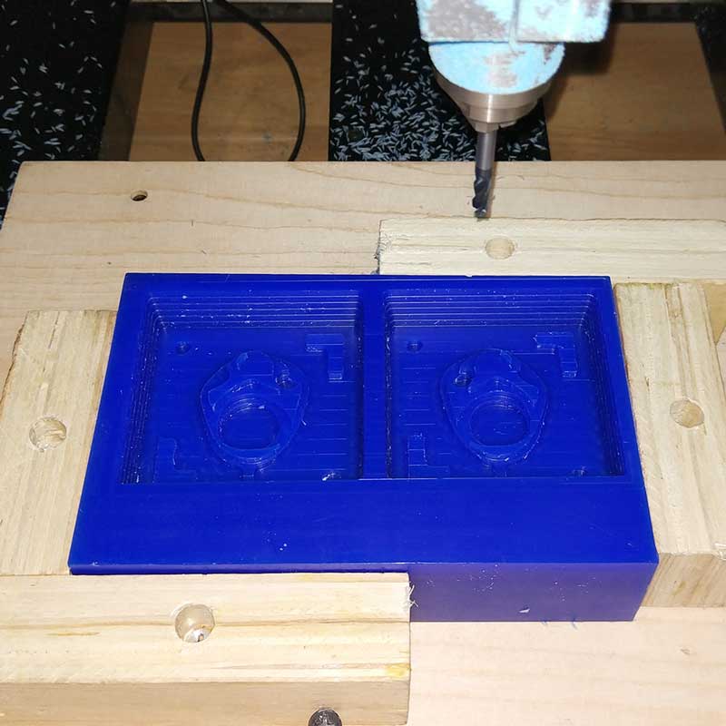
_MILLING THE MOLD
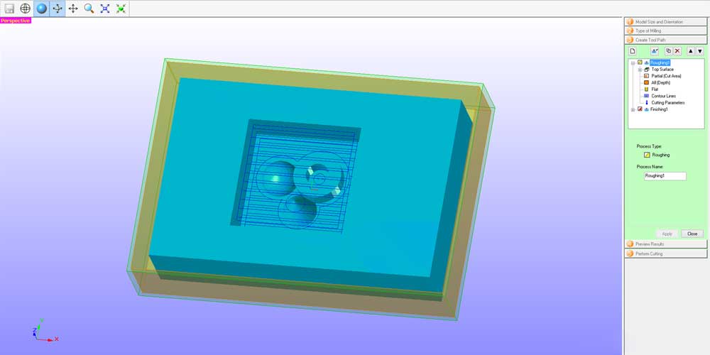
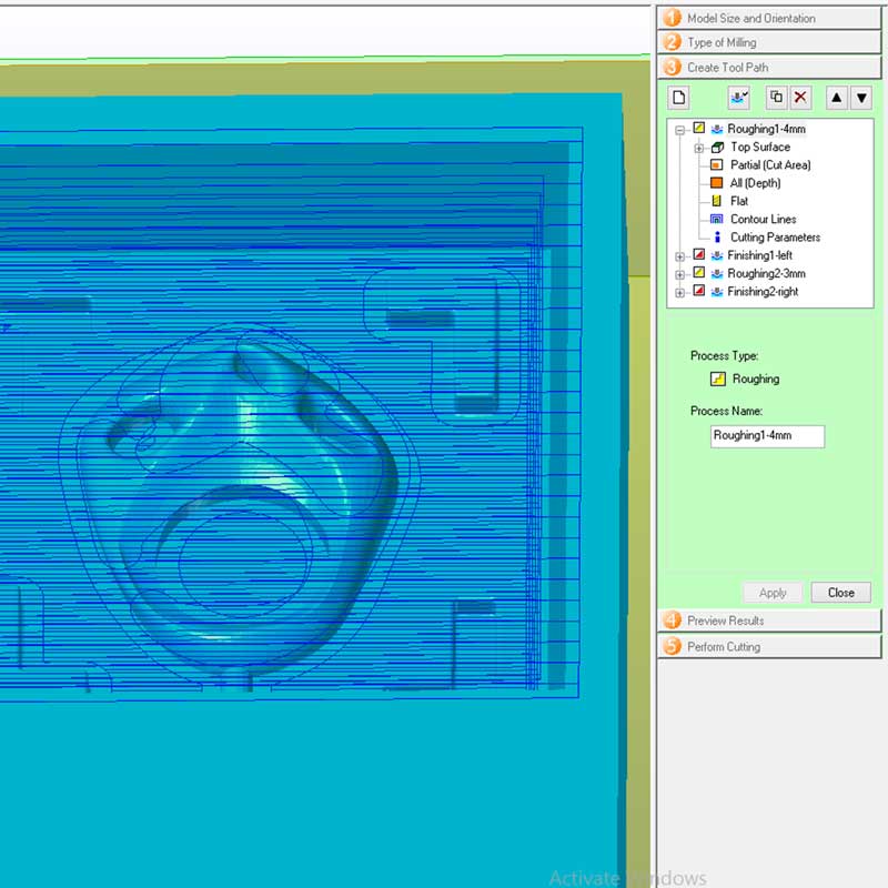
As I mentioned above we will be using a Roland MDX-40A for the milling, and the software we used to do the traces is SRP PLAYER. In this software you have to specify the settings you will be using for each task, and you will need at least two tasks, one rough setting and one finishing setting.
For my work I decided to do:
1_Roughing with a 4mm square endmill
2_Roughing with a 3mm square endmill
3_Finishing with a 1mm round ball endmill
I will explain what the following parameters mean below:
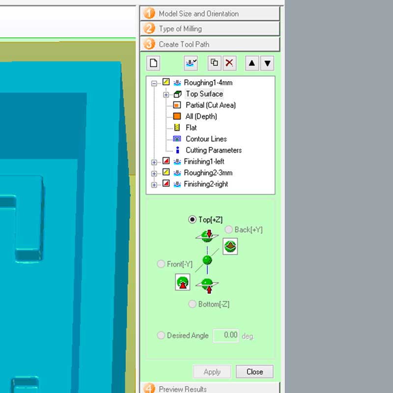
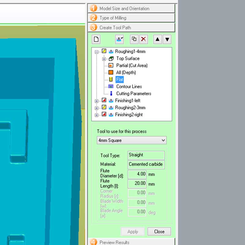
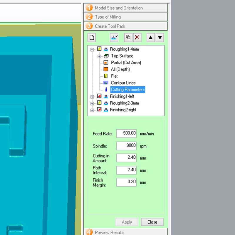
Parameters have to be set for each task and they will depend on the tooling you choose:
1_TOP SURFACE: where is located your model to cut.
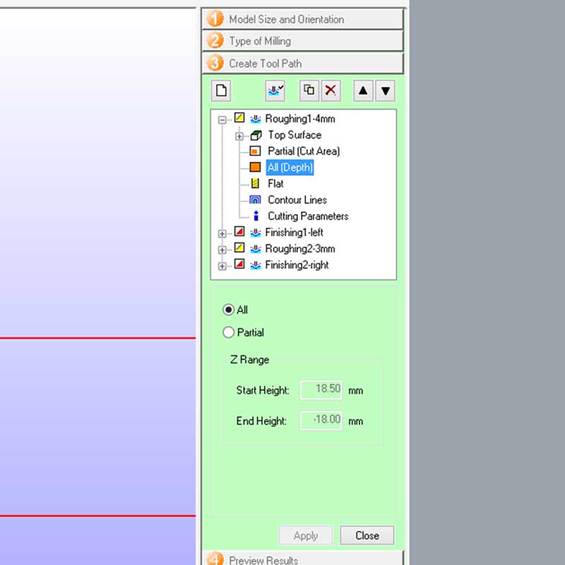
2_PARTIAL (CUT AREA):, this is the cutting area, you can manually decide the size of the cutting
area, this is usful when doing a finishing cut where you only need to carve in specific areas, otherwise
the task would take too long if your working area is big.
3_ALL(DEPTH): as the partial cut area, you can decide the depth area as well, form where to where
the endmill has to dig.
4_PROFILE OF YOUR ENDMILL: here you choose the type of endmill.
5_CONTOUR LINES: type and direction of contour lines. NOTE: the cutting in amount
is like the layer height, the smaller the value, longer it will the task and higher the resolution, same
thing for the path interval, which is the offset between each path.
Ok, so I set up all my tasks and the working estimated time was 3.5hrs.
Once you have your paths you have to save the toolpaths, this program will create and save a toolpath
for each task individually, that then we will load into the machine.
After you have generated your paths you have to open the Roland Vpanel for MDX-40A, here the first thing you want to do is locate the Z axis using the sensor, then the XY and after that you can load the tasks and begin cutting.
NOTE & TIPS: remember to fix very well your stock material, by no means it should move.
Before using the wax stock I had available I did a test using rigid foam, this way I could test the
first task and check that everything worked.
It was very useful doing this, because when I started the task I noticed the endmill was going beyond
the stock material, that is when I realized that my file was horizontal and I put the foam vertically.
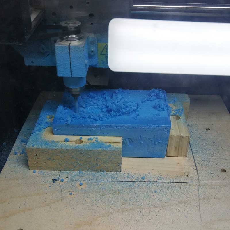
Once I checked all was good I started the task using the castable wax.
_ERROR lost the task...
During the first task, the roughing, encouraged by a classmate, I decided to stop the task and clean the
wax accumulated, so I pressed VIEW on the machine and opened the lid, but... it was too
soon to open the lid so the machine didn't do VIEW properly, and I lost that task that I was doing
because the machine took this as a "mistake" and I had to restart all over again.
Restarting wouldn't be an issue as this was just the first task, so it didn't pass much time, the
problem was the XY positioning has been lost, meaning it would almost impossible to use that surface of
the wax precisely where I had started, so I decided to flip the wax and use the back, but before doing
that I filled with some extra wax the deepest hole that has been dug, just in case, I didn't want to
risk having a hole in my wax.
After flipping the wax I restarted all over, fortunately this was the first task if this would have happened almost at the end of the 3.5hrs of work, it would have been worst.
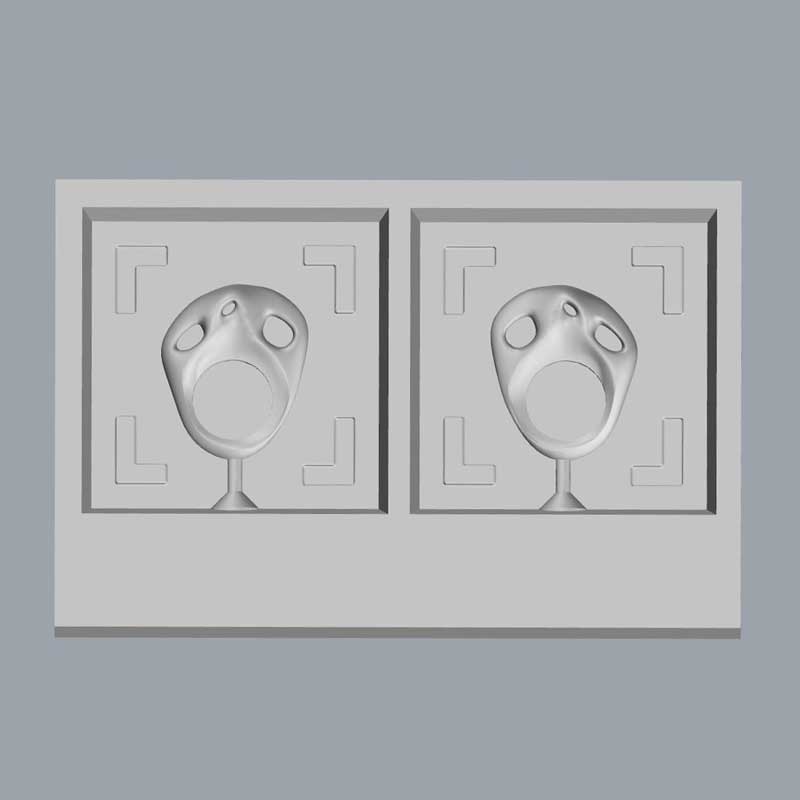
The rest of the process went smooth, although I have to add that during the finishing task, the shank of the endmill was hitting the edges of the mold and this is becuase of the detail of the hole of the mold I did, it is a cone that touches the edges of the wall.
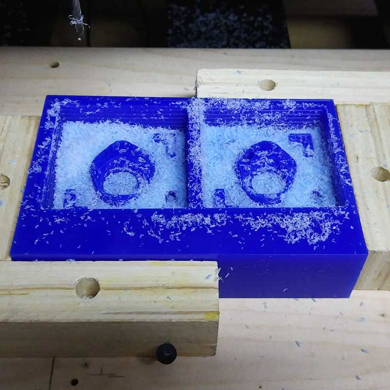
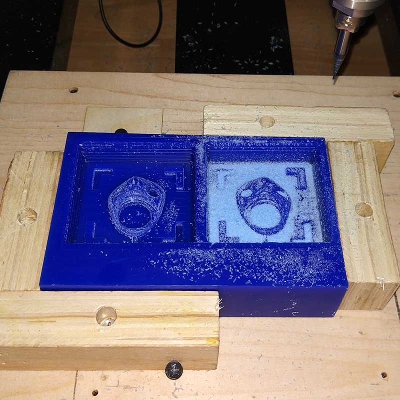
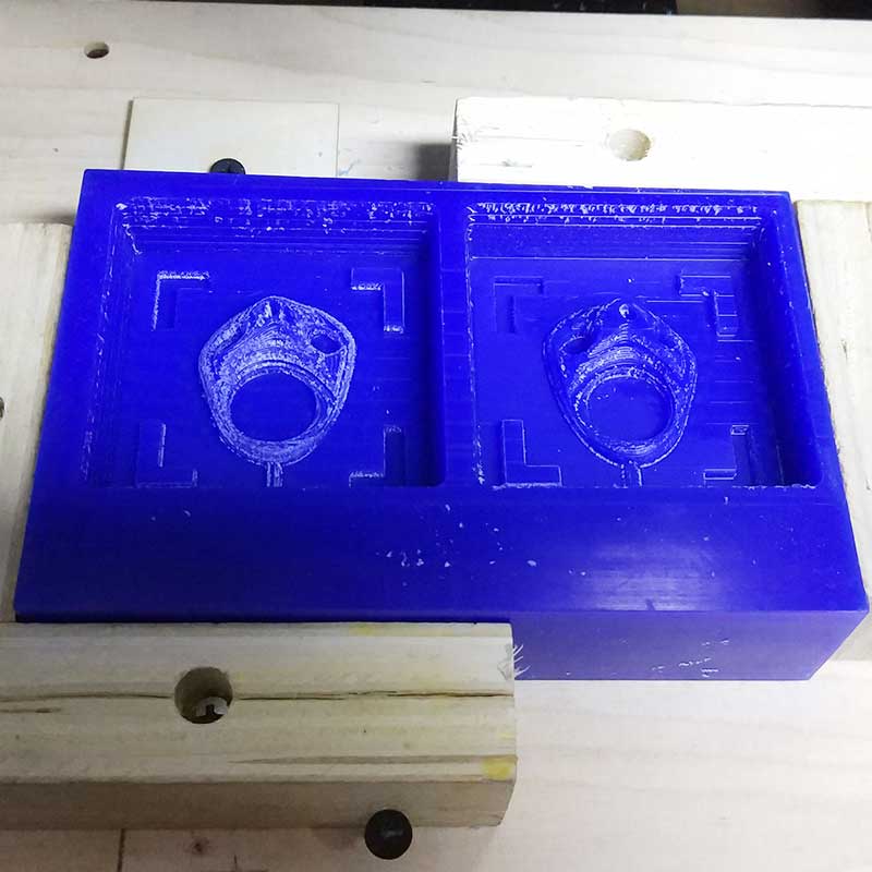
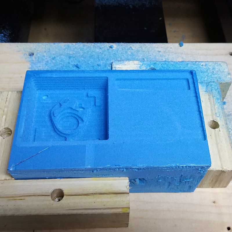
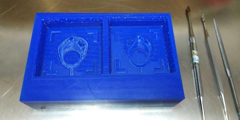
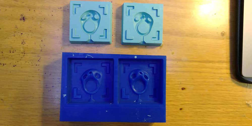
_MILLING RESULTS
As you can see from the last photo, the details of one side of the mold where very rough. I am not sure
what could have been the issue as the settings where the same for both sides.
One thing could be that the ZERO AXIS wax block a bit too high, causing the layers to be that big,
another thing could be that, while the tasks where running, at some point I noticed the was moved a
little bit, even though I used two L wooden shapes to fix the wax, so I added an extra support.
I would like to understand what was the issue, maybe the settings as well?
I plan to re-do this model as I would like to have a higher defitinition on the surface for both sides
of the model.
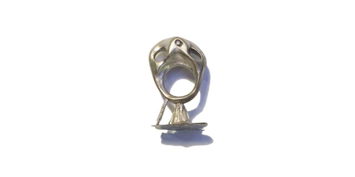
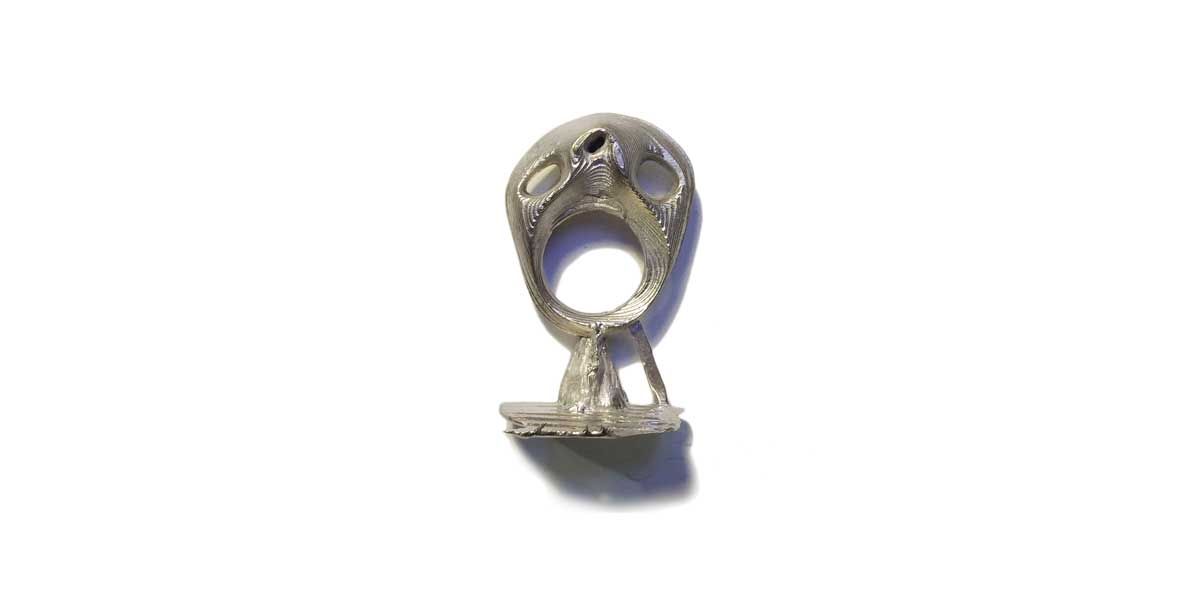
So I had one side a bit rough where you could see the layers, but that the outcome was fine, and the other side that was super rough, so I decided to do some post-processing cleaning. And as I've worked before modelling jewelry in wax and I have the tooling at home, I decided to take home the block wax and smoothen a the right side of the mold.
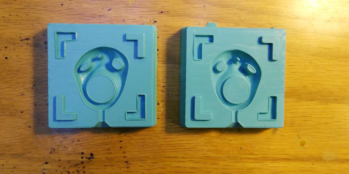
_MILLING ERROR & SOLUTION
After checking my file together with my instructor, we found two major issues why I had such a rough
surface on the side B of my mold.
The reasons are:
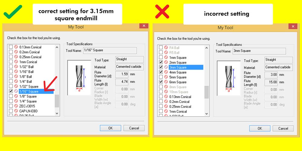
1_INCORRECT ENDMILL SETTING: For my roughing tasks I mentioned above I had two tasks, one with a
4mm square endmill and one with a 3.15mm square endmill. When choosing the settings for the 3.15mm
roughing task, I choose a profile of 3mm square.
Although this 0.15mm may have seen insignificant for me at that moment, for the machine is a huge gap of
difference. So this is one of the main reasons why the result was so rough.
2_Z AXIS: Another reason why the side B of the mold was so rough could have been because the block of wax was not touching entirely the sacrificial layer, causing a shift on the Z axis and creating such a big gap between each layer.
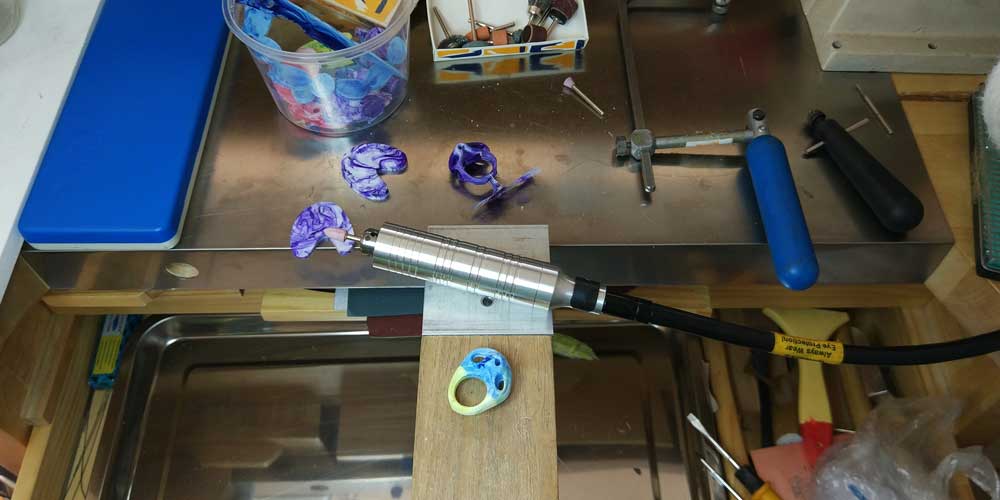
_HAND-MADE POST PROCESSING
Wax is a lovely material, and something I learnt in University is that even if you break a small detail
on your model or you made a mistake, there is always room to fix it.
With some wax carving knifes and if you have a wax welder (like soldering iron used in PCB production),
you can fix or tweak your model.
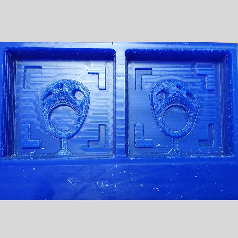
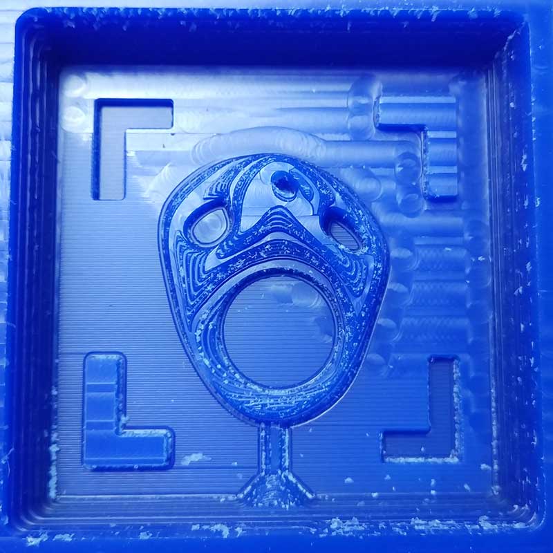
Here is the before and after. I only fixed the right side, the left I just cleaned it with baby oil, I didn't want to smooth the layers as I like that effect, plus I wanted to have one side of the mold completely done by the machine and another side fixed by hand, just to play with the contrast of machine and hand-made.
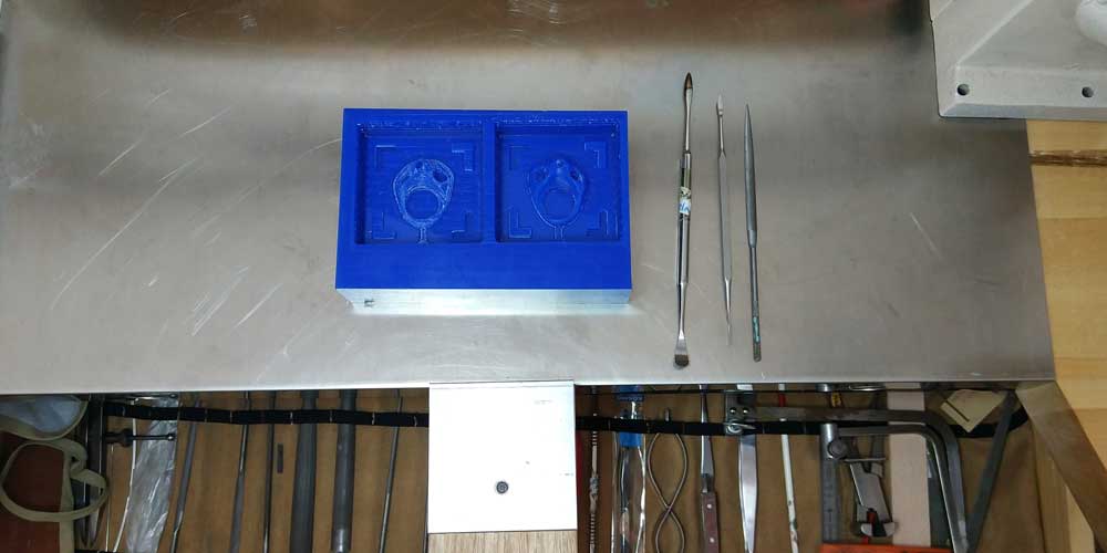
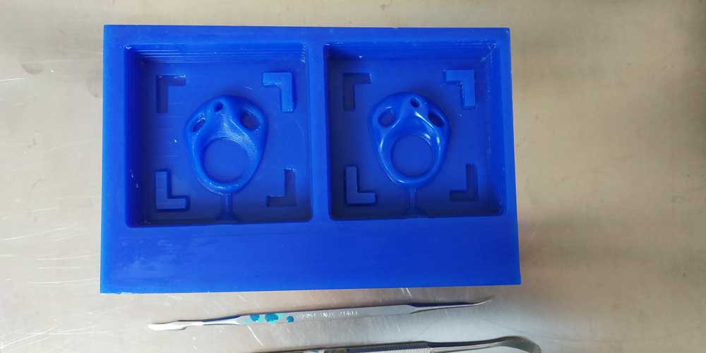
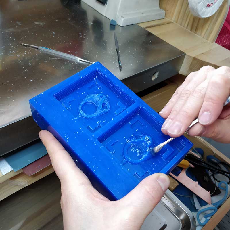
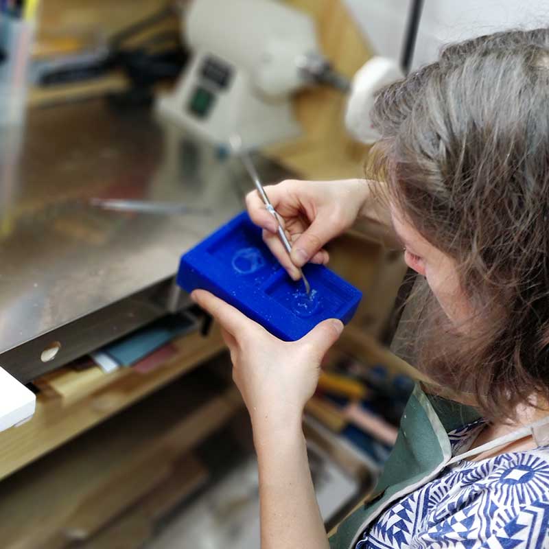
_MAKING THE MOLD
This is the nicest part!
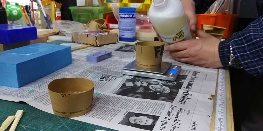
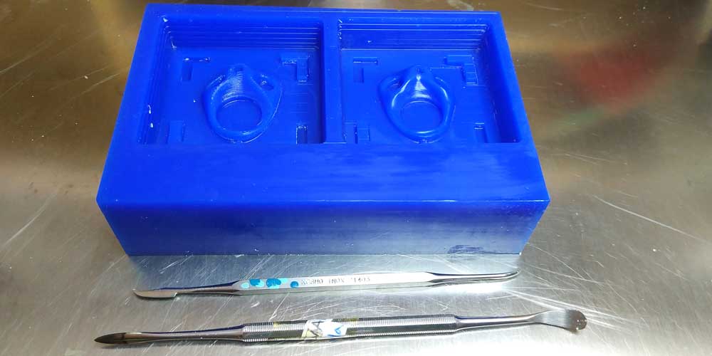
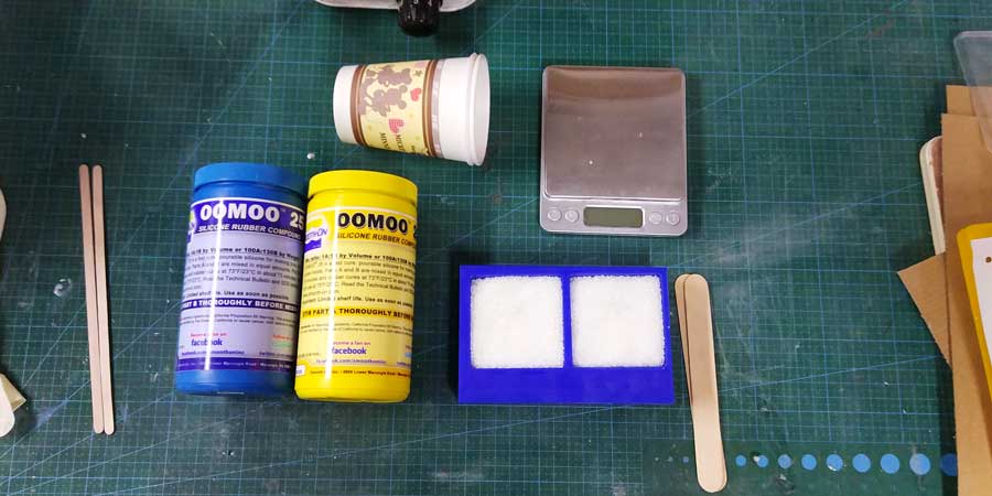
So once I had my mold ready, I did the silicone mold.
As I explained above, I will be using OOMOO-25 for the silicone mold, and to make the mold you have to
mix two compounds, and the amount of liquid you need depends on the volume of the negative of the mold
you did previously.
I used Rhinoceros and calculated I would be needing 106grams of silicone.
And as this type of silicone is mixed using two compounds, you have to calculate either by weight (A=100
B=130) or by volume (equal parts A+B).
As I did some post processing on the mold (smooth by hand), I thought the volume wouldn't be the same any
more, so I got some sugar and filled the wax mold with it, I weight the sugar and it gave me 83.3grams
for both molds, so then you can use a rule of 3 to calculate how much PART A and PART B of the OOMOO-25
you will be needing, or you can use the super useful online platform that SMOOTH-ON has,
where you can even calculate the volume of the silicone needed.
Check this link for their online convertor:
SMOOTH-ON CALCULATOR
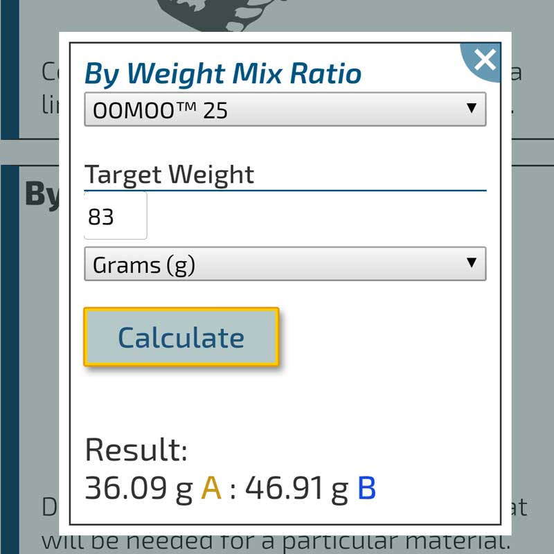
In the end, 83grams was enough only for one mold, so I did one mold first and then I did a new mix for the second mold.
TIPS & TRICKS WHEN POURING: when mixing both components don't do scoop movements do circular
movements to avoid creating bubble.
Before pouring the mixture, use a brush to apply some mix into the smallest areas (like holes) so to
make sure that the mix reaches those parts.
Then when pouring the silicone into the mold, start pouring at the lowest point of the mold and don't
move from there, let the mixture spread like sea waves.
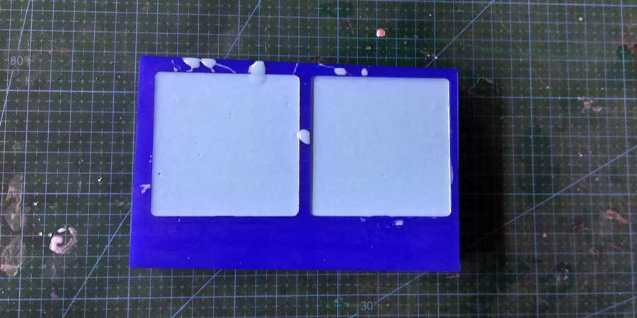
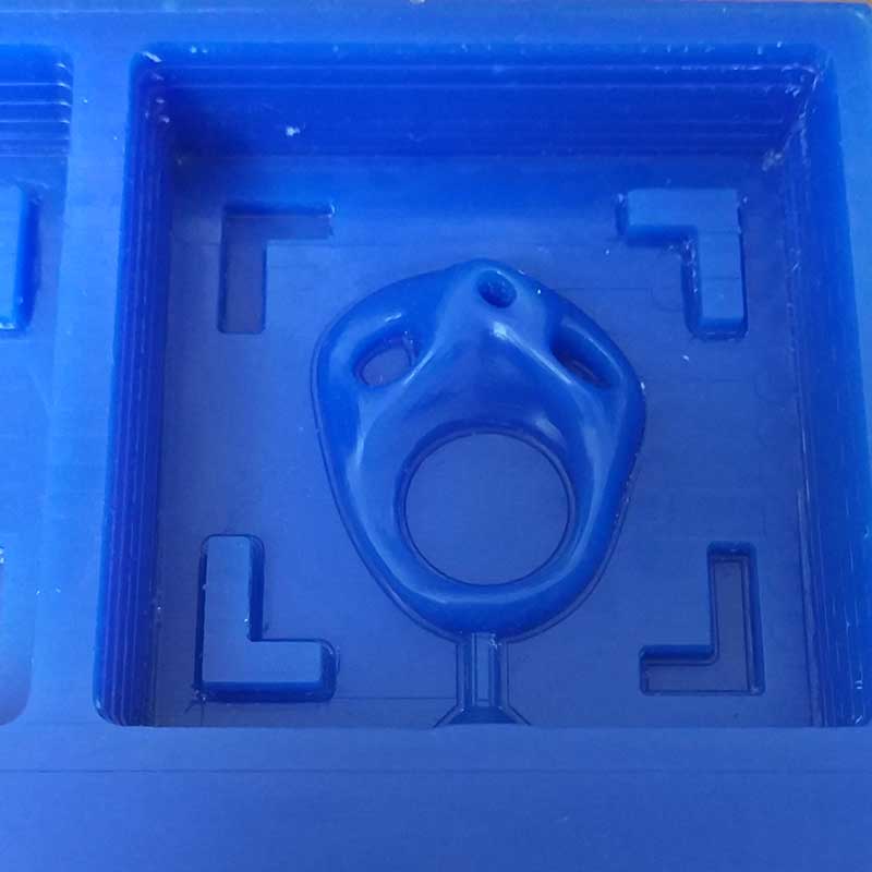
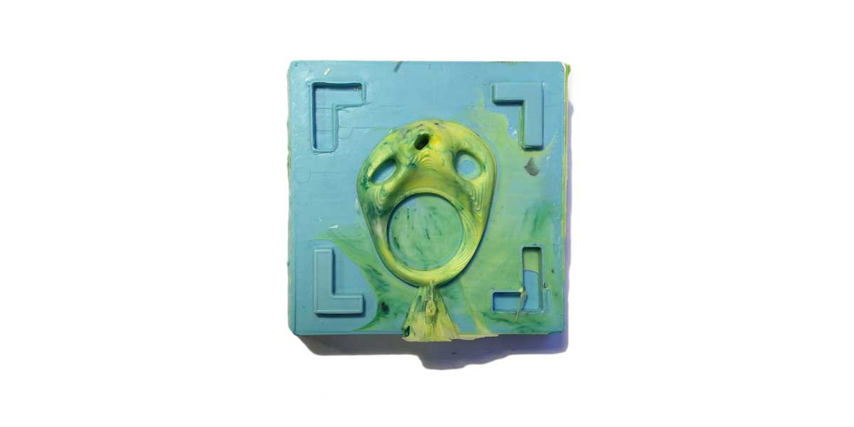
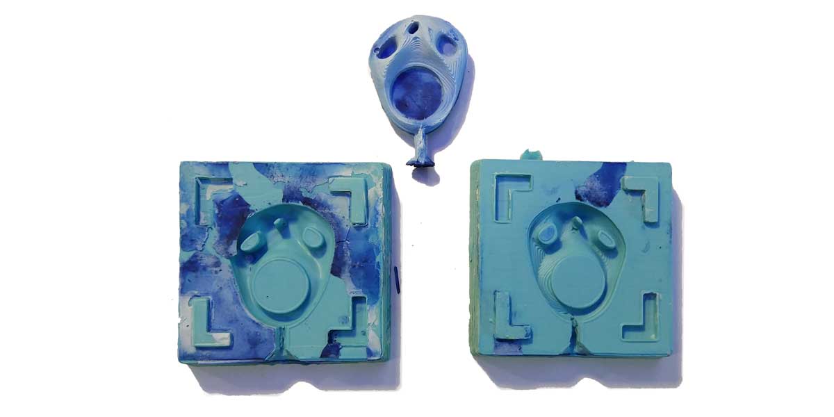
_MOLD OUTCOMES
The first silicone I ever made from scratch came out pretty good!
No bubbles and all the areas where covered! am happy with the result of the moldm specially because one
side has this beautiful texture of the layers and the other side of the mold is very smooth.
The only thing I need to improve is the hole to pour the casting material, I would say increase the cone
size and the diameter of the canal at least 2-3mm more, so that it flows correctly.
_CASTING & EXPERIMENTATION
Ok so this is the nasty part... but one of my favourites also!
Get ready to get dirty so prepare your working area and your outfit...
_USING RESIN
The first casting material I used was a fast cast polyurethane casting resin from XENCAST (you can find
more info above on the group assignment summary).
This resin has two compounds, the resin and the hardener compound. Before you use them is important that
you keep in mind the following information:
Components "A" and "B" should be mixed together quickly and thoroughly by hand at a ratio
of 1:1 by weight.
The resin must be poured into the mould quickly as the pot-life of Xencast P6 is very short (less
than 6 mins). If you are degassing the resin, either before pouring or in-mould, make sure you can
undertake this within the 5-6min pot-life
(source:
XENCAST website
)
The amount to use is 1:1 for both components, and remember that its pot life is very short so you have a couple of minutes before it gets hard, so prepare in advance your working are and your molds.
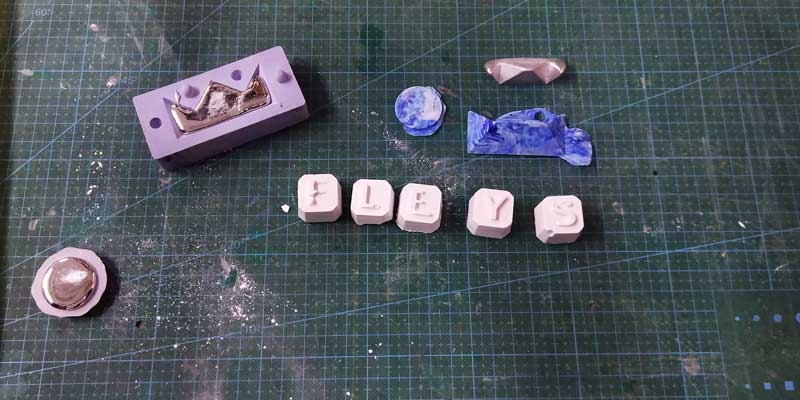
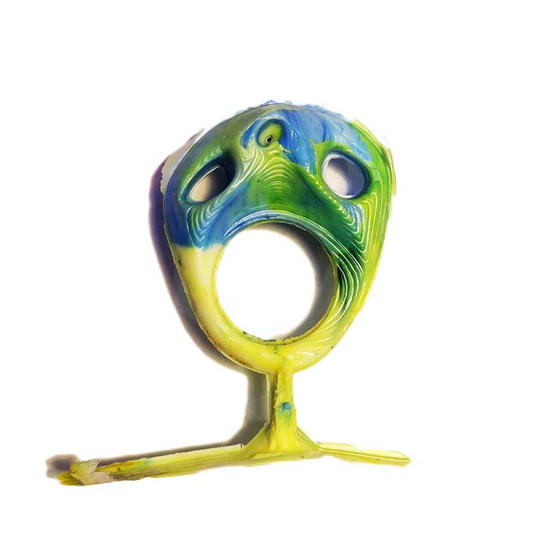
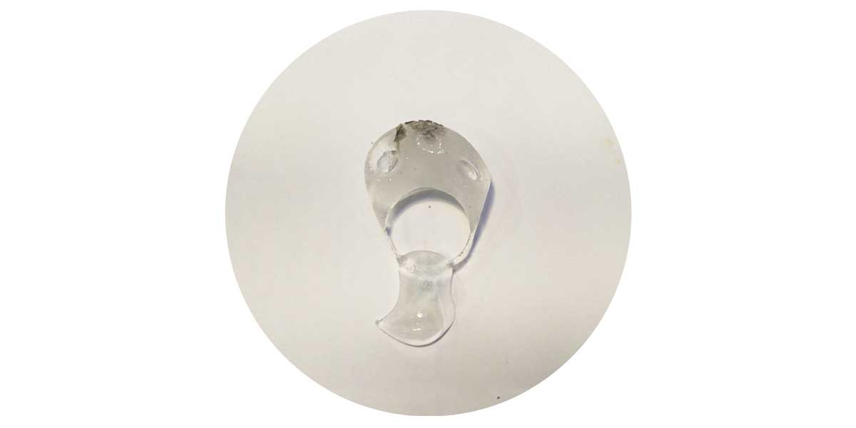
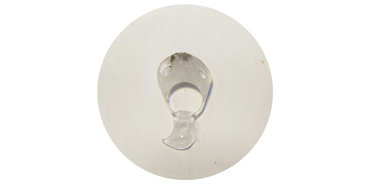
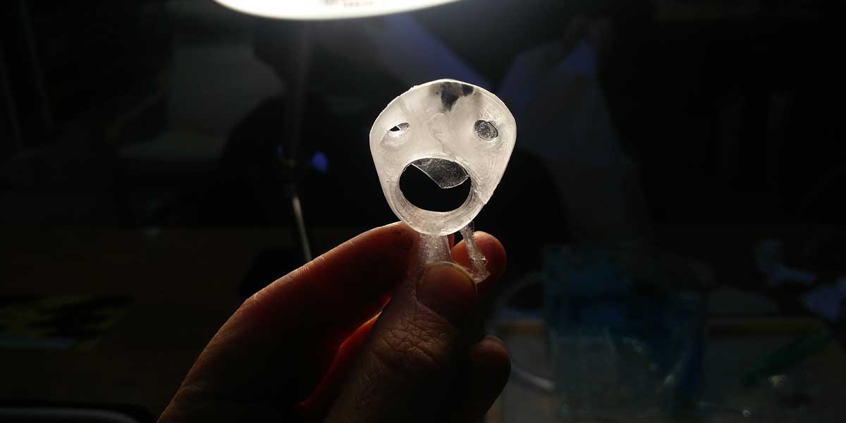
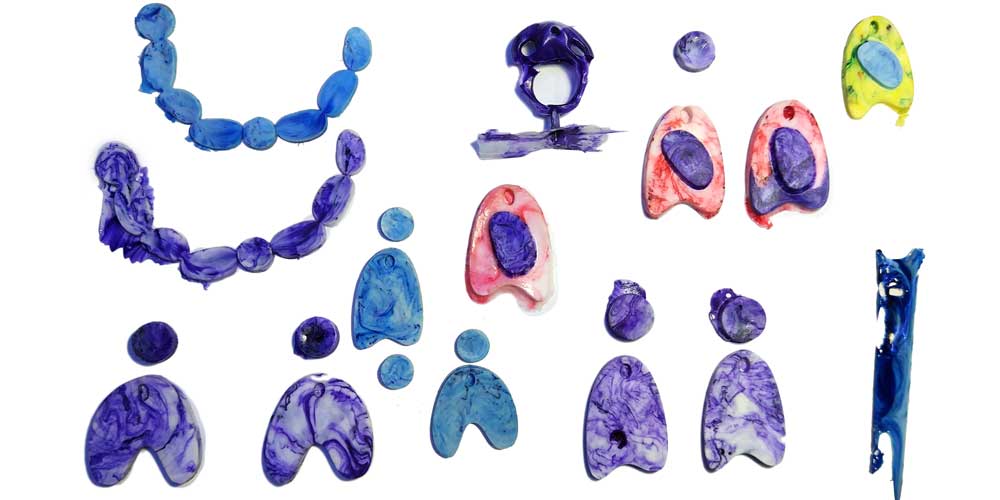
The first test I did, the resin I poured didn't reachead all the shape, so I had this first outcome:
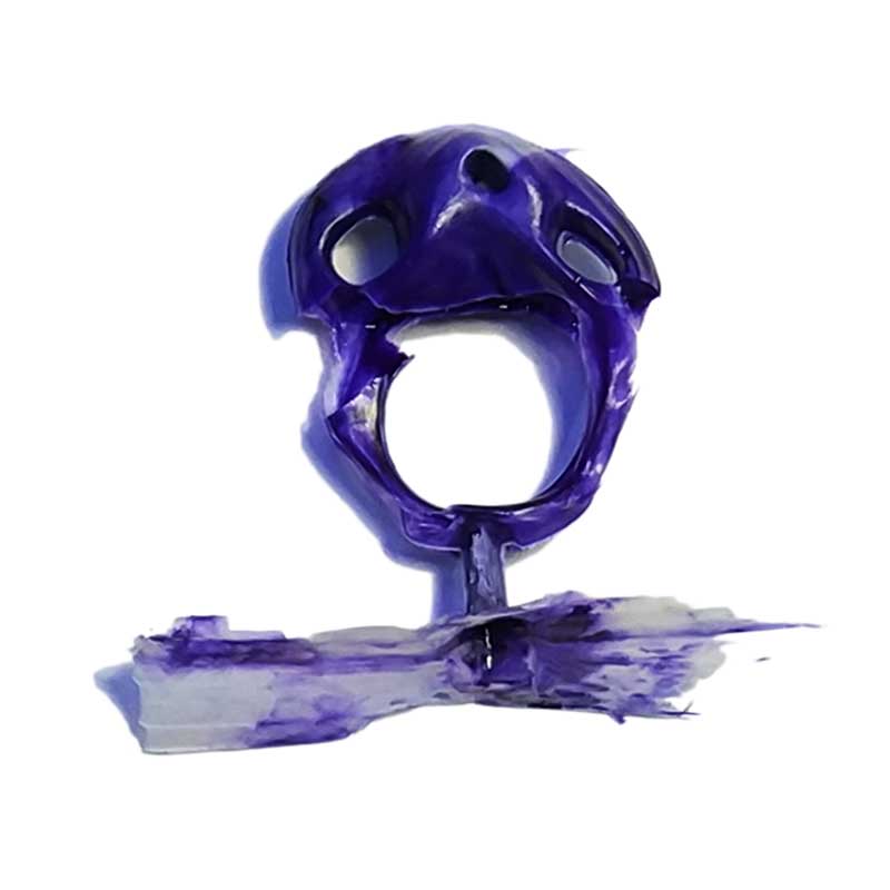
I then did a second test and I had the same problem but the cool thing about the resin is that you can
pour more resin into a dry resin and it will stick. So I did two pourings (i used different colors) and
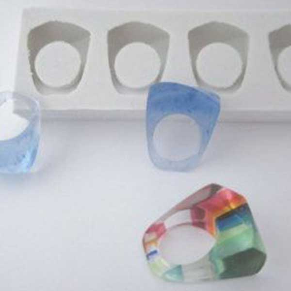
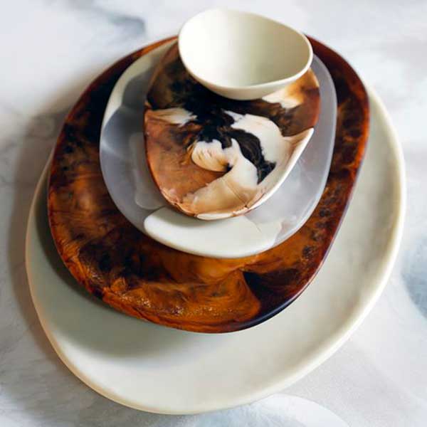
I got the complete ring!
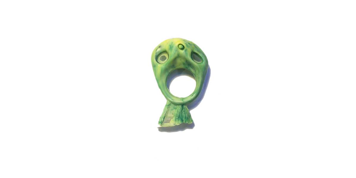
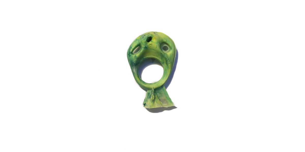
With the colors I used and the marble effect I did wheh mixing, it came out a cool result!
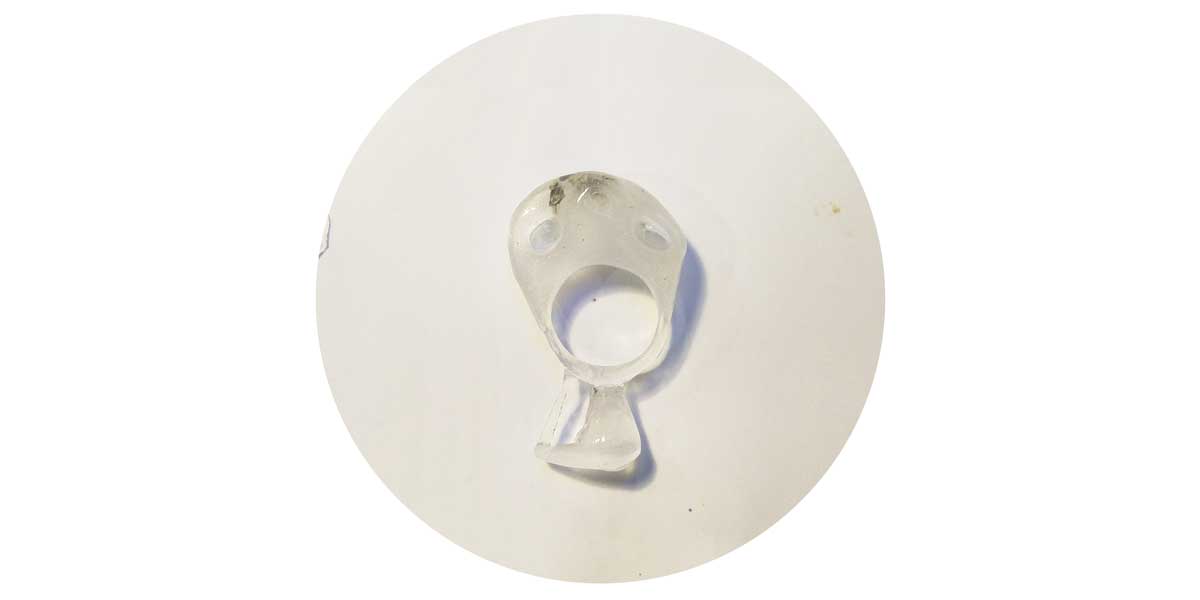
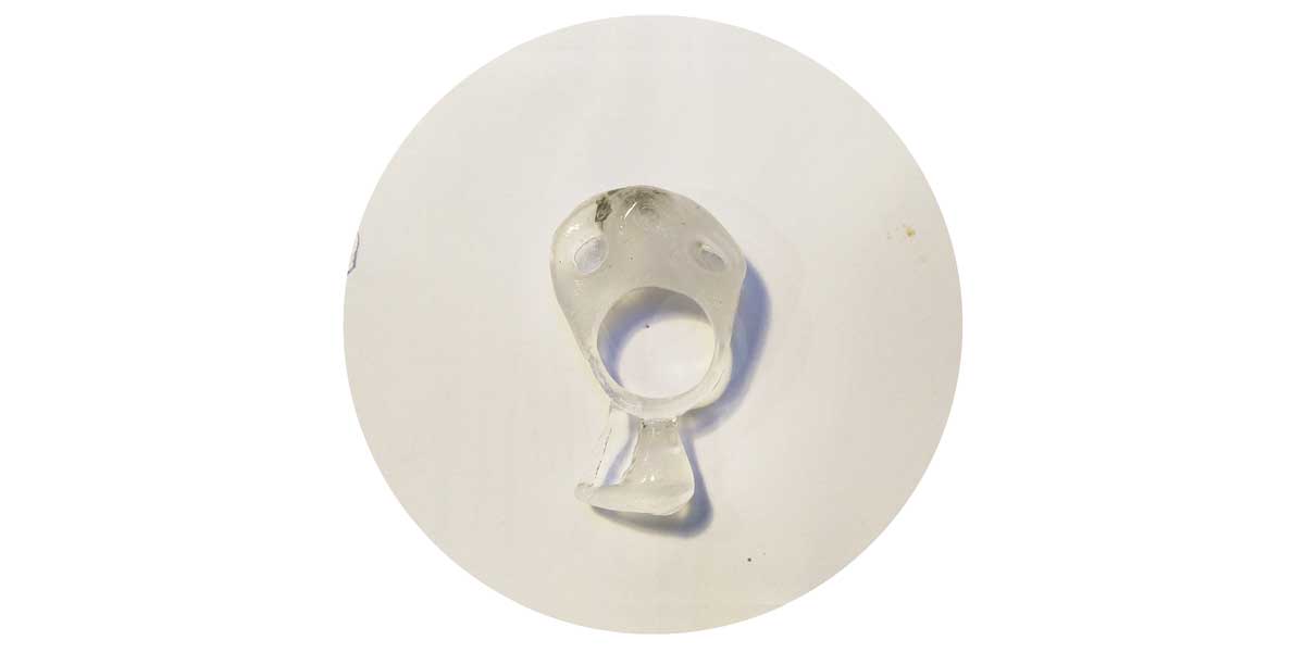
This is the second test:
I still have to clean the ring and upload some photos of the final result, will do so the next days =), stay tunned...
I really liked working with resin, so I went crazy and decided to do some other molds using laser cutting and vacuum molding. =P
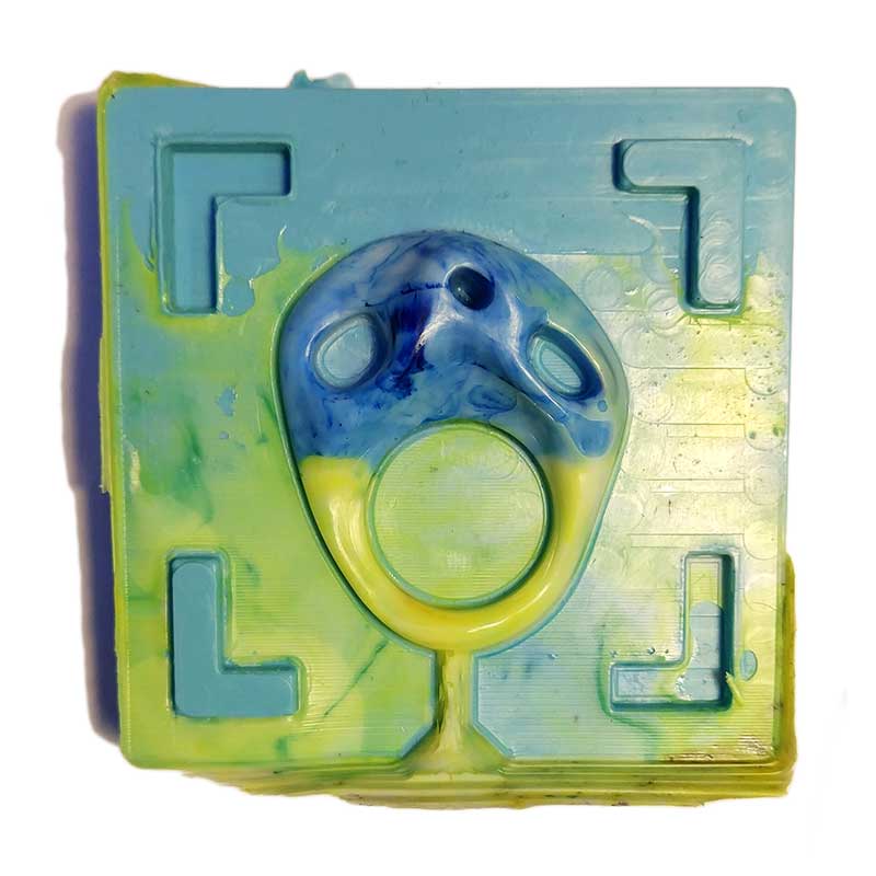
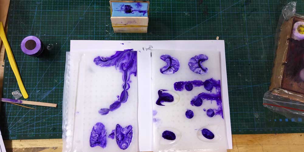
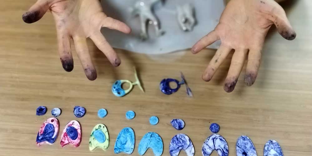
_MORE RESIN TESTS
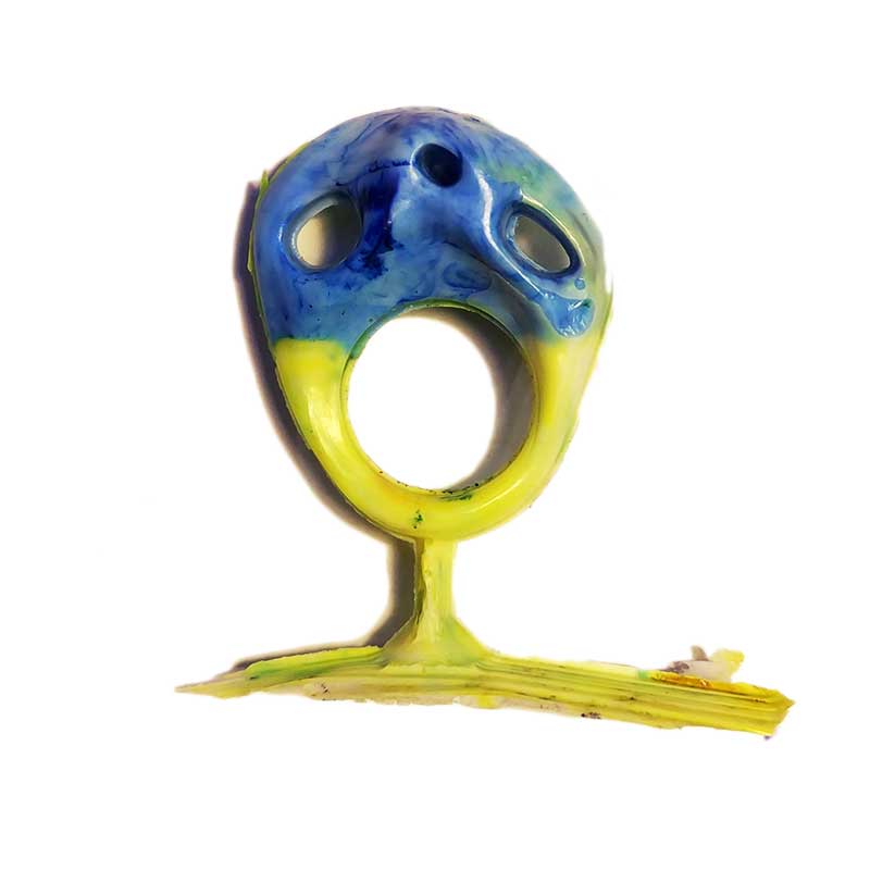
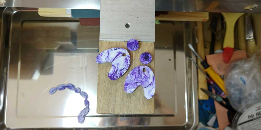
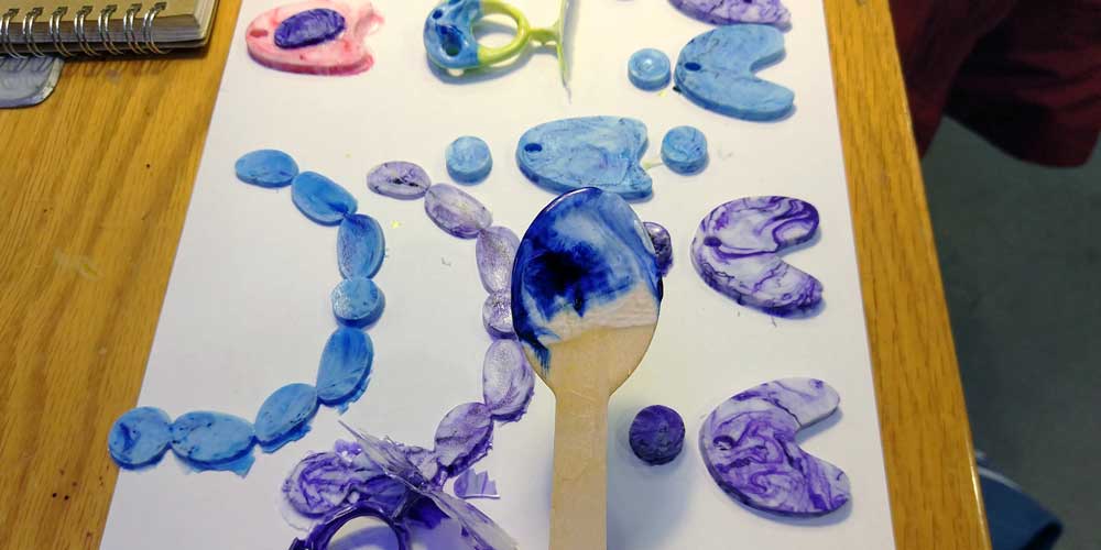
Using the same mold, and resins and pigments I did a few more variations.
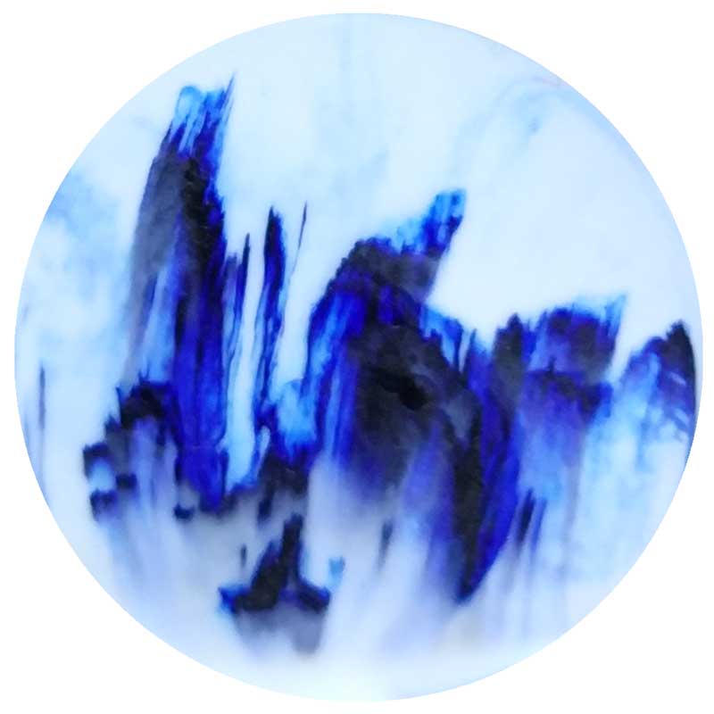
Here I used white and a bit of blue pigment:
Here I mixed green, yellow and white resin:
_USING DRY STONE+COLORANT
I did some tests in my ring mold using dry stone and I added blue pigment to the mix.
Here are the results:
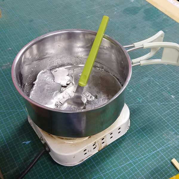
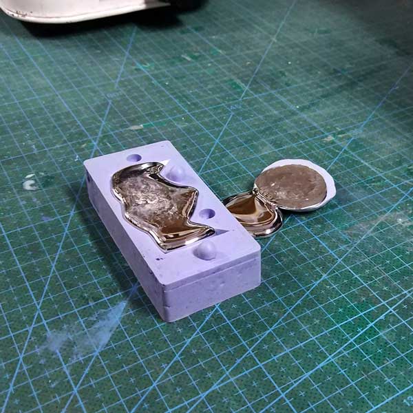
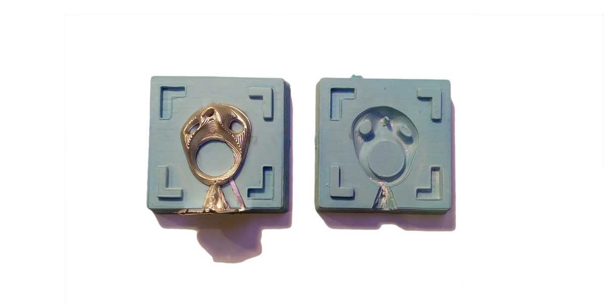
_USING METAL
We have at the lab low melt fusible bismuth based alloy so I decided to give it a try and use it in my mold.
This alloy melts at a very low temperature point (100-100 celsius degrees), so it's easy to test it using a simple electrical stove to heat it.
I have to say it is not a great idea using metal on this silicone mold, maybe once or twice is fine, but if you plan to keep using your mold for long maybe do't cast this alloy too often, I noticed the mold was getting some stains.
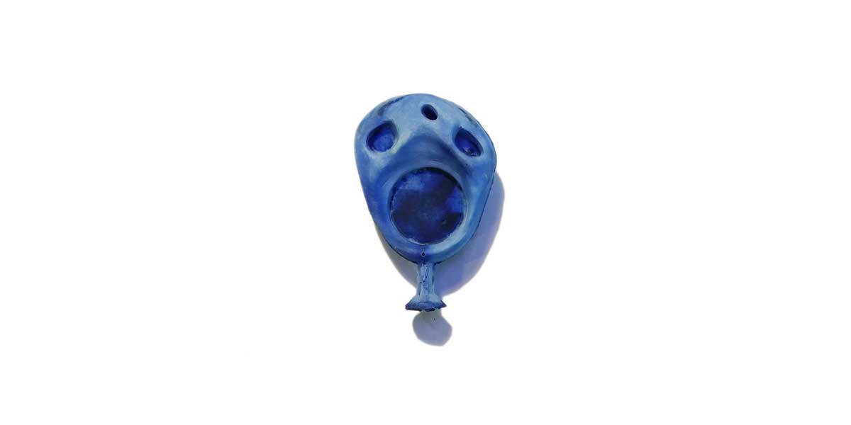
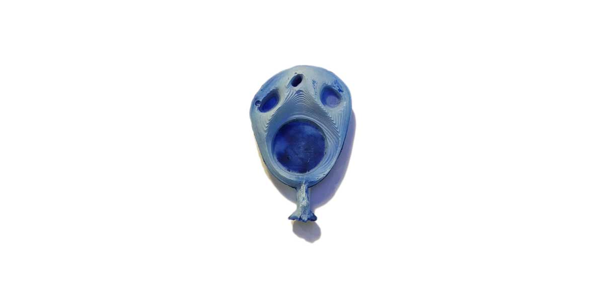
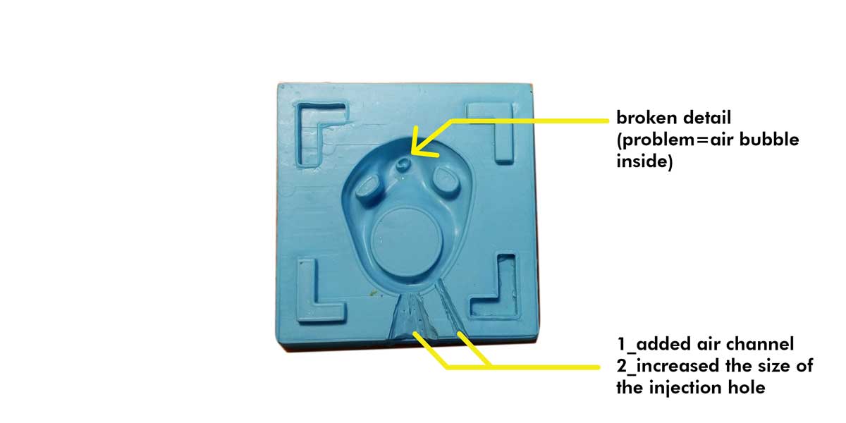
Something else that happened to my mold, but it was not entiirely because I casted metal, is that one
part of th mold broke (a tiny detail in the holes), this happened becuase that tiny part had air bubbles
so it has hollowed inside, and as a result when pouring hot material, it dettached.
I forgot to mention after my regional review advised by the instructions, before doing the pouring of
the metal alloy I increased the injection channel and I added an exit for the air.
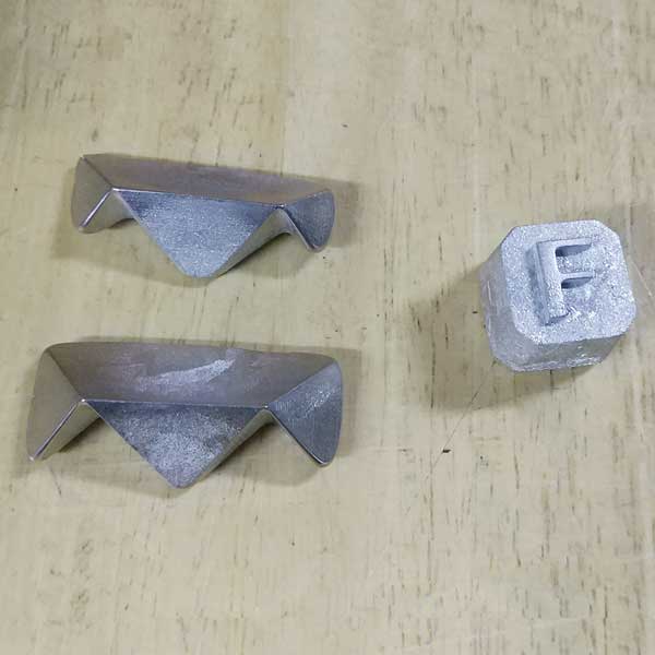
Here are the results of the metal casting:
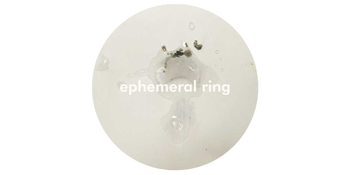
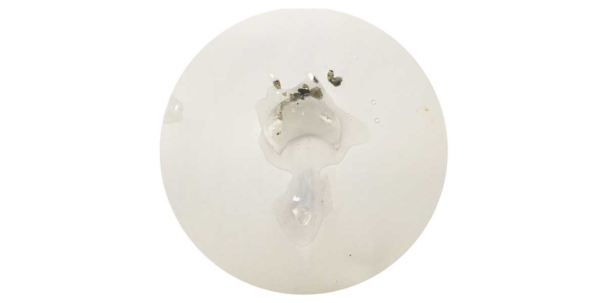
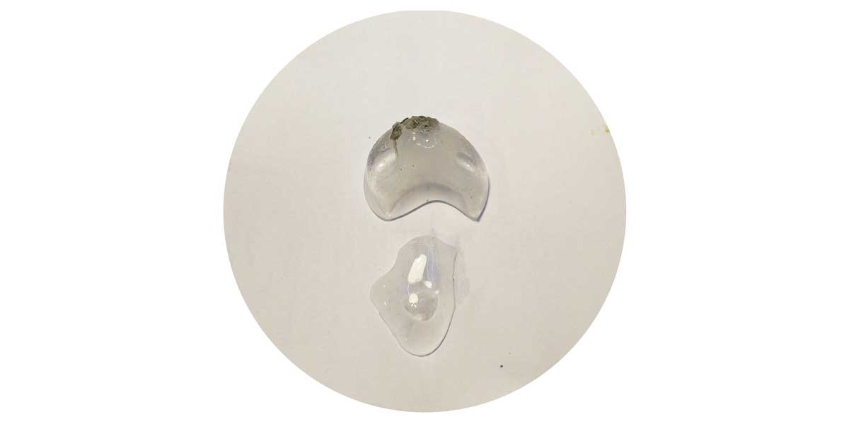
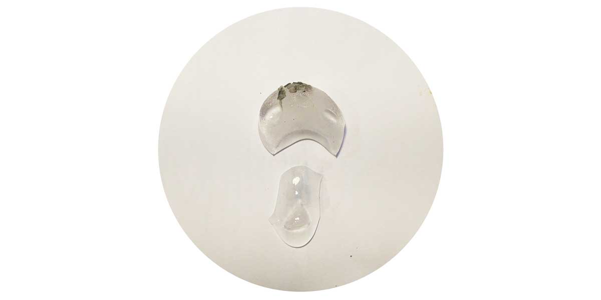
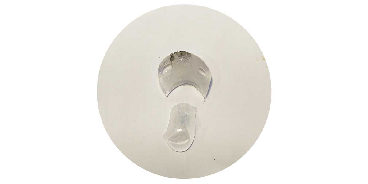
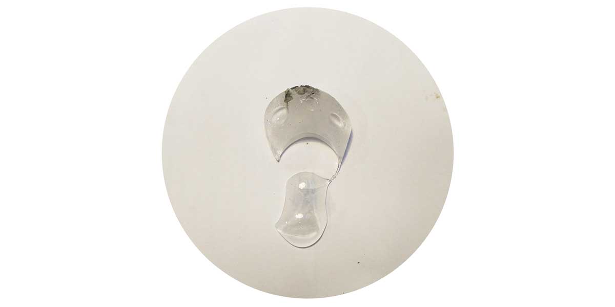
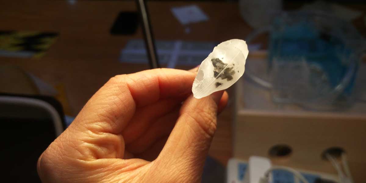
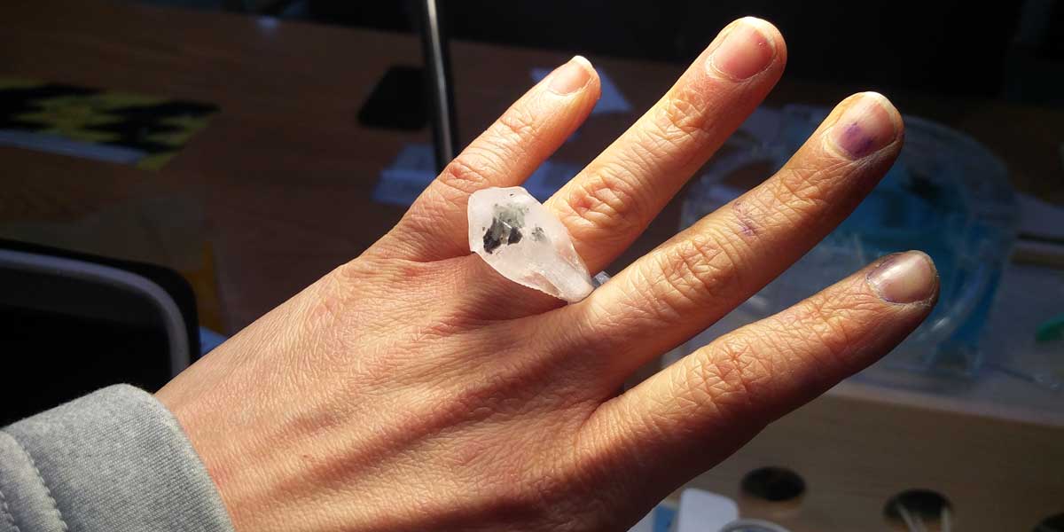
_EPHEMERAL RING
The idea of this ring is to wear something temporal that it's shape changes quickly in the time. An
ephimeral jewel that is made of water and pieces of rock.
It will be always the same material but will transform.
The idea behind the tiny pieces of rock, is that you can keep them once the ring melts, maybe I could replace them for tiny gold pebbles and develop this into an ephemeral collection in the future.
The matter and the state of matter:
_POPSICLE RING
Another attempt putting my mold in the fridge, but this time I put carrot juice.
This is just an
initial idea of a line of rings that are edible, popsicle licking rings, perfect for the summer =P

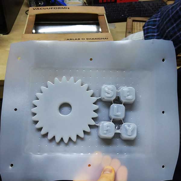
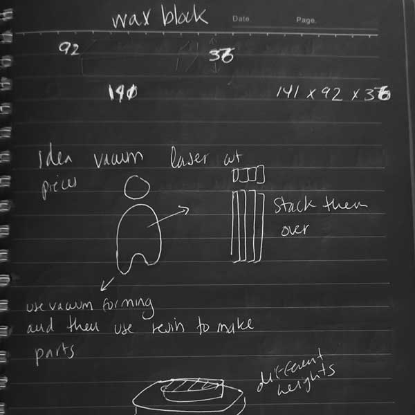
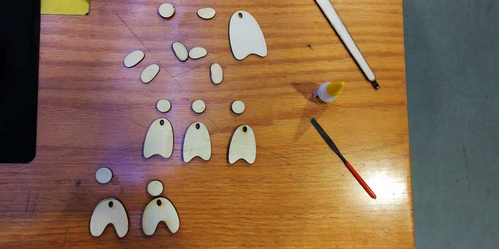
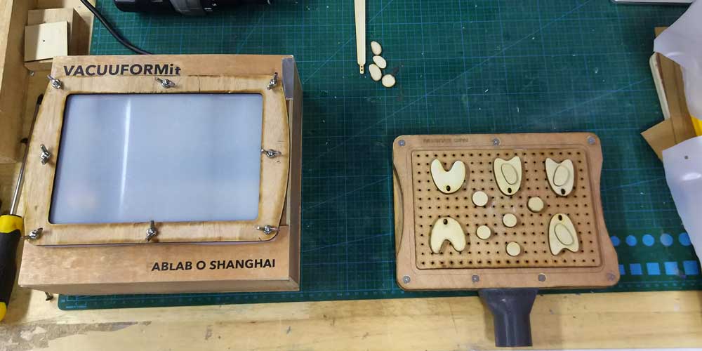
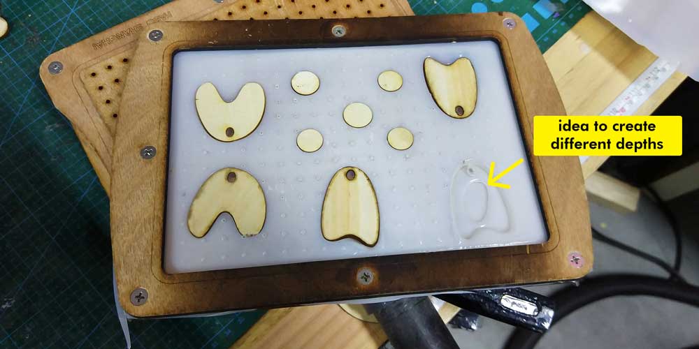
_VACUUM MOLDING
Inspired by this assignment, I decided to make some molds with the vacuum molding.
The idea I had was to laser cut some shapes to make some earrings and stack them to have more depth and
different layers.
The plastic I am using to make the mold is recycled HDPE fomr bottles of water.
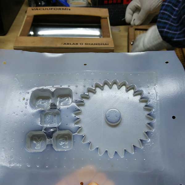
After preparing my molds I did some casting using the same resin I used above for the ring.
I have to
add, I prepared this mold while my silicone mold was drying, this way when I did all the resin mixing I
could use the extra material to pour it in this new molds.
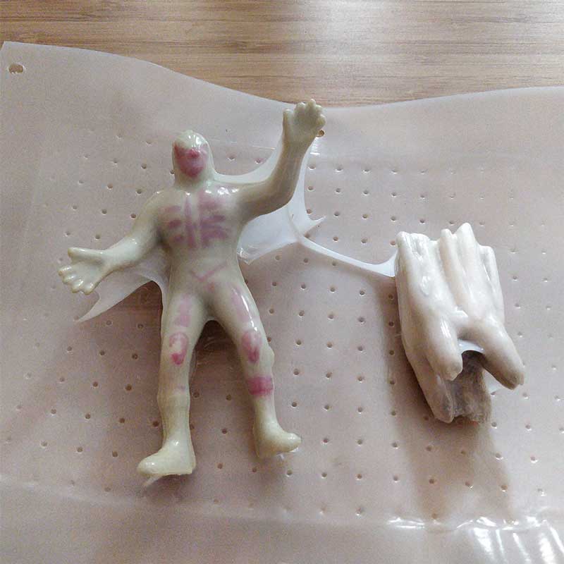
_failed trapped LUCHADOR
I wanted to experiment a bit with the vacuum molding, and I used some LUCHADOR toy and a cow's tooth to make some molds, but... I called this more "The trapped Luchador and tooth".
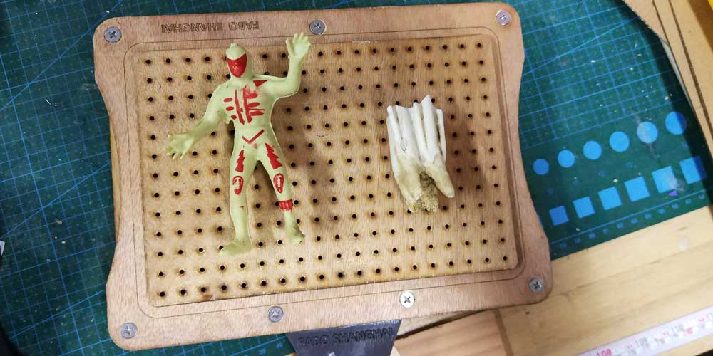
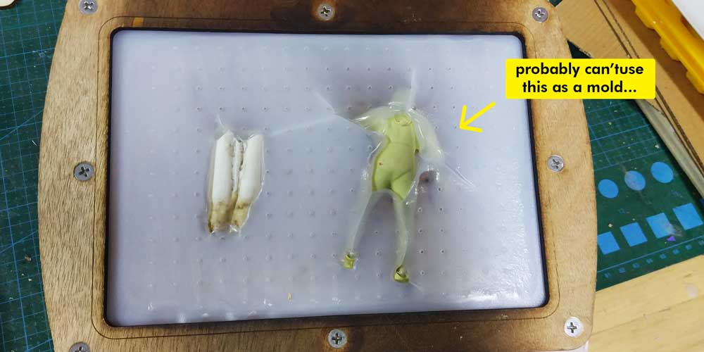
Heheh maybe I can't use it as a mold, but I loved the way they look now, if I want to make a mold out of this shape I will cut in laser the silhouette of both shapes and stick it behind so that when I vacuum the shape I will keep a flat surface behind and will be able to pull out the figures.
This also gave me some ideas more for packkaging design... I would definetely like to keep experimenting with the vacuum molding.
_CONCLUSIONS & IDEAS
I really enjoyed this assignment and so I dont't forget it, this is what I will and want to do:
1_FOR THE MOLD: I would like to experiment more mix using hand made and machine made, as I did to
correct my mold.
2_I would like to make some molds using laser cutting and laser engraving. Cutting the layers in
wood or acrylic then glue them together to make a mold.
3_Try other materials (cement, recycled plastic, metal powder, stone grains...) in the cast mixing.
Oh, and remember wear gloves this week!
_DOWNLOAD FILES
_Earrings 2D mold file (you can open a PDF in Illustrator as it preserves the layers)