Week 06: Electronic Design
In Week 4, we have learned about PCB board, milling, soldering and programming the board. The focus of this week is to design our own PCB board and running AVR program with the board. To do that, we have covered circuit design, components and symbols, PCB CAD software (Autodesk Eagle) and AVR programming.
What is a circuit?
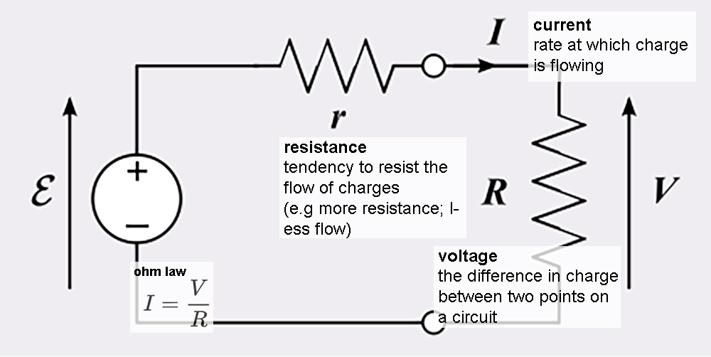
Before we talk about circuit, first it is necessary to know that electricity is created by the movement of electrons, which create charges that allows work (e.g. lightbulb, phone, laptop, etc. to turn on and off). A circuit is a closed loop that allows charge to move from one place to another. Components in the circuit allow us to control this charge and use it to do work.
More basics on electricity can be found on this Sparkfun introduction.
Group Assignment
This week we learned to use an oscilloscope from Sreejith Mohanan, a former Fab Academy student. An oscilloscope is a test instrument that visualizes varying signal voltages. When building a circuit, an oscilloscope allows you to check the continuity of charge flows between your components. Please refer to Pamela’s documentation for further details.
Individual Assignment
The assignment this week is to recreate the Hello World circuit, attaching a LED and a button on the board and running the Hello World program provided by Neil.
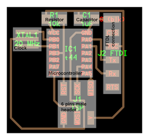
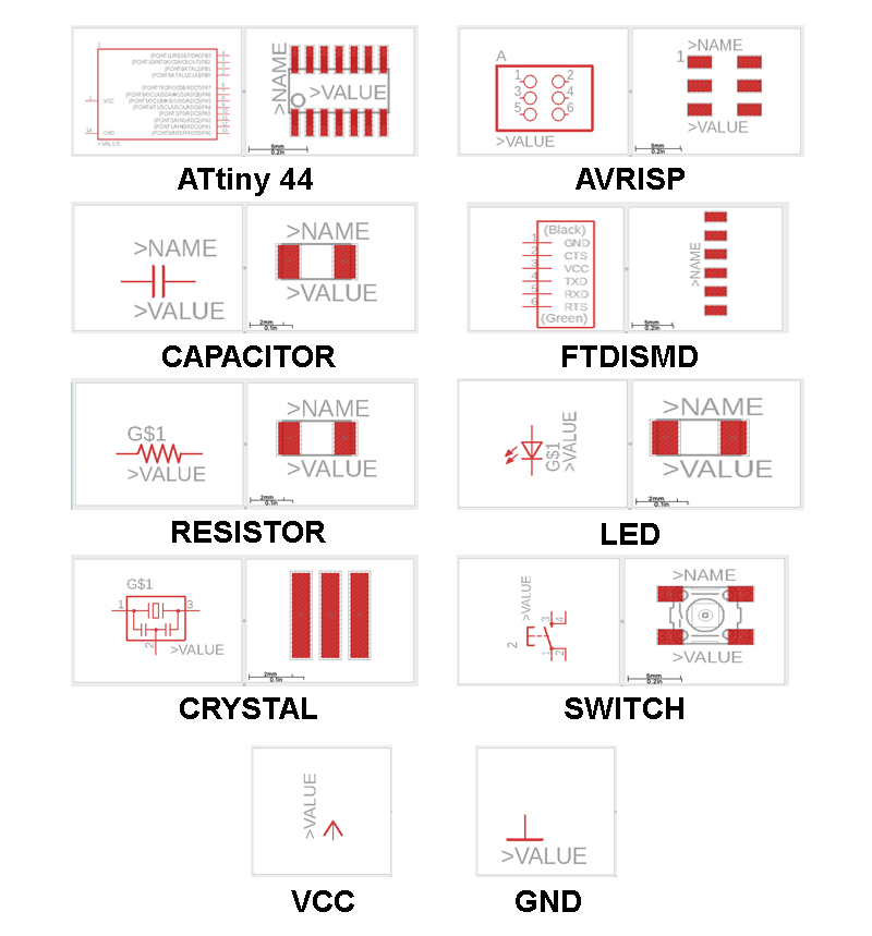
Here are the components on this board:
- Microcontroller (attiny t44)
- the brain of the circuit
- Resistor
- comes with a specific electrical value; it limits the flow of the electrons through a circuit
- Capacitor
- stores energy; it suppress voltage spikes and cleans voltage circuit
- FTDL connection
- 6 pins male header (ISP connection)
- Clock
- aligns the frequency of all the components to the same timing
Here are the components that will be added onto this board:
- Button
- used to interrupt a wire, opening/closing the circuit when pressed/switched
- LED
- converts electronic energy into digital switch light
Important tags:
- VCC
- positive relative to ground
- GNC
- ground/zero volts; a reference point relative to which other voltages in the circuit
Eagle
Before getting started, downloard the Fab Eagle Library. It contains all the components that will be used this week.
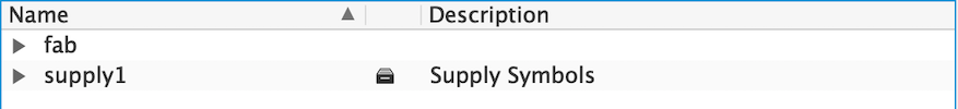
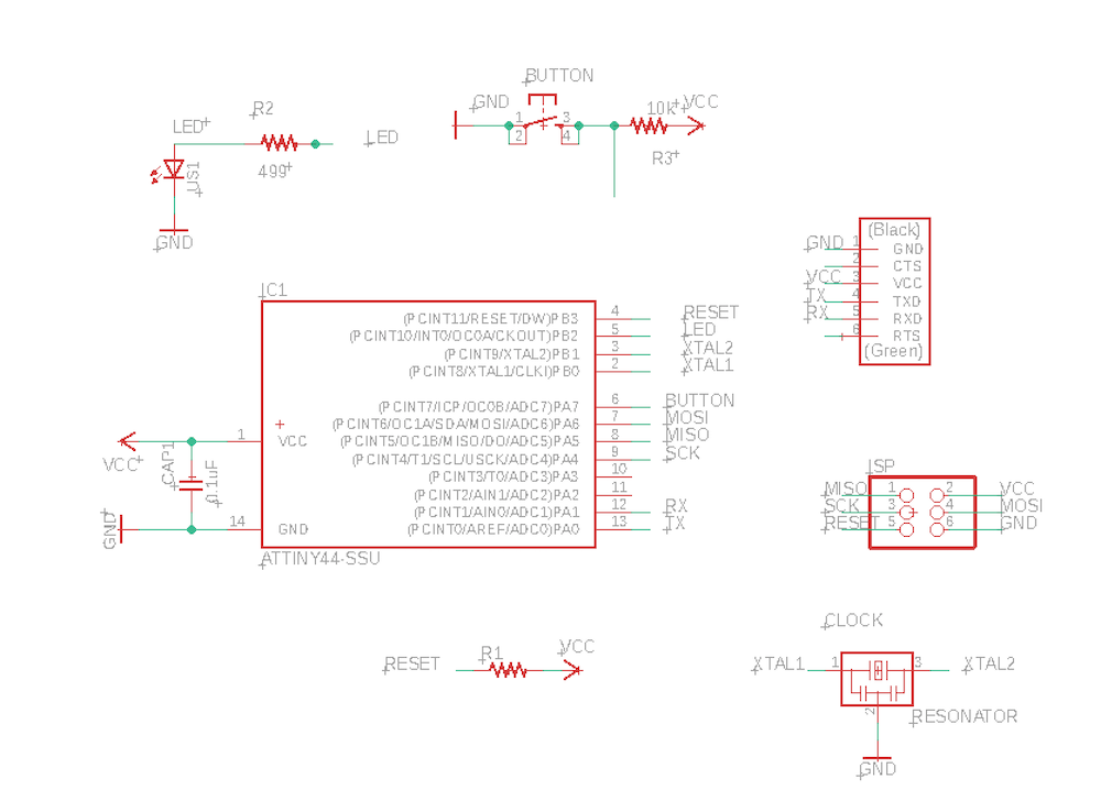
First, I have designed the circuit of the Hello World Board in Eagle. Under Library/Open Library Manager, make sure you have fab (where all the components you will need are found) and supply 1 (where VCC and GNC can be found) library under In Use.
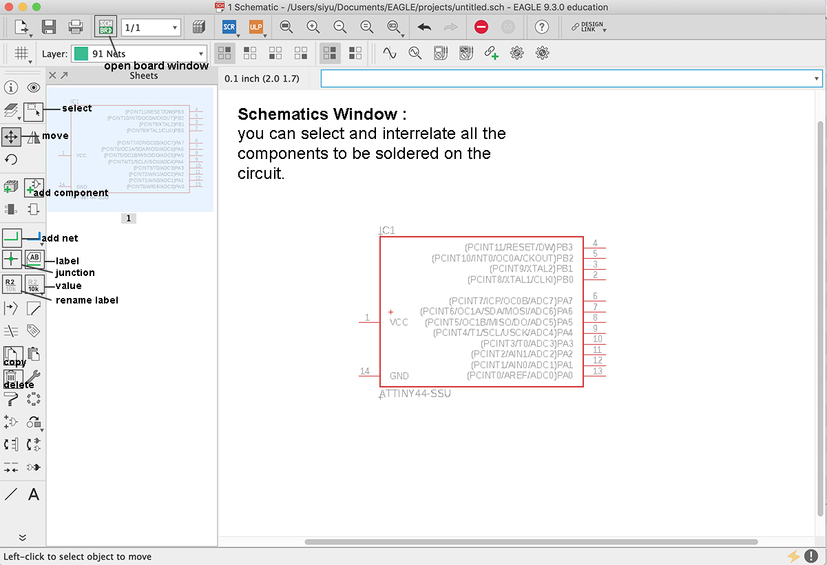
In the schematics window, add all the components that you will need for the hello world board. Make sure wires are added as well. These will be the traces of the PCB.
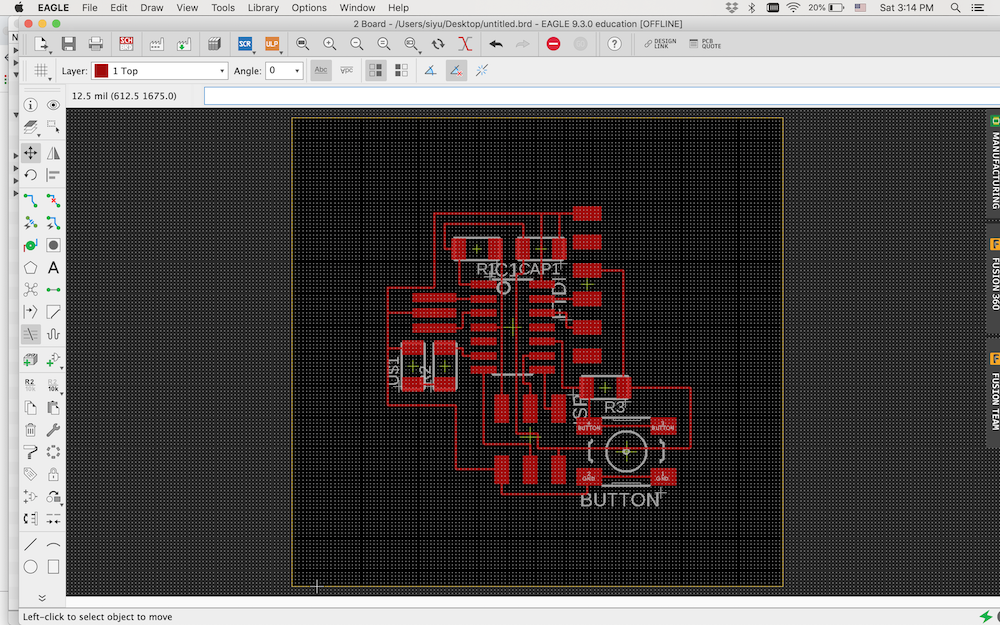
Once all the components and wires are added, switch to the board window. Here is how it looks like:
Once all the components and wires are added, switch to the board window. Here is how it looks like:
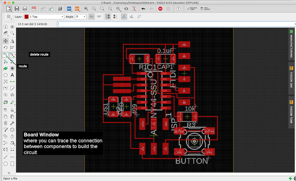
However, when you just switched to the board window, all your components are intertwined like this:
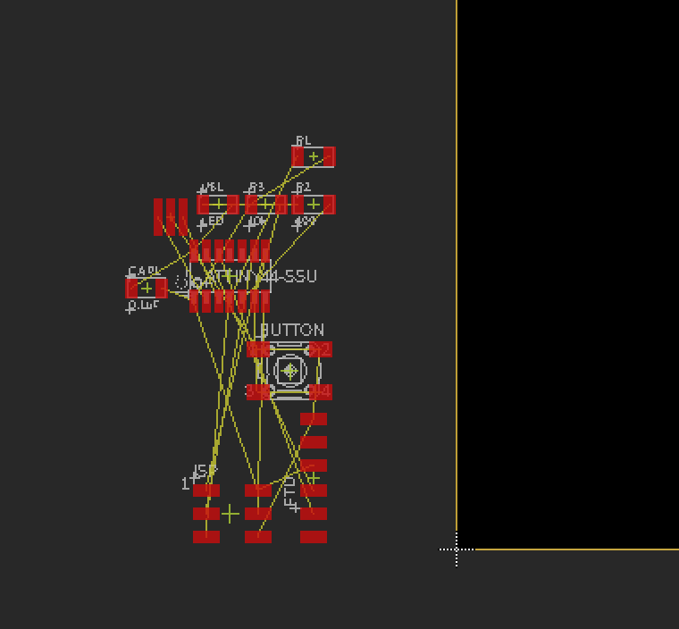
You need to route the traces on the board. After dragging all the components onto the board, you can resize the board by clicking on each side of the board with the Move tool
Tips on arranging the components and the traces:
- Since ATtiny controls all the parts on the PCB board, I have placed it in the middle of the board.
- Make sure all the components need VCC/GNC are near the ATtiny/ISP legs with VCC/GNC.
- Traces can go through ATtiny, button, capacitor and ISP.
- Don’t have traces going through between the legs of the components, e.g an ATtiny leg
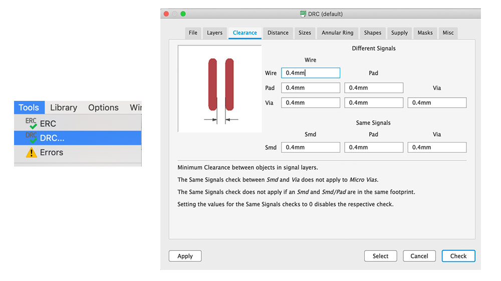
- Check for design errors (DRC) (such as air wire, wire stub, distance between traces, etc).
Downloard the Fab DRC. This design rule ensures the gap in between the circuit is enough for a 0.4 mm endmill to pass through.
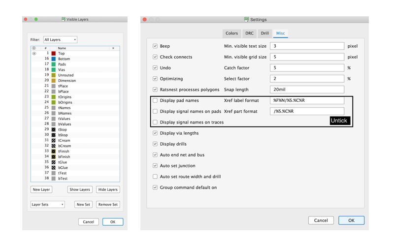
Before exporting from Eagle, under Layer, only the Top layer needs to be visible. Then, under Setting/Misc, hide the names remaining on the board.
Export the board as a Bitmap image in 1000dpi. NOTE: remember the dimension of the image, since Photoshop doubles the dimension of the image.
Prepare image for milling
Since the image of the board is doubled in dimension when imported into Photoshop, I first changed the dimension of the image. Then, I made the outline of the board and added some graphics on the trace:
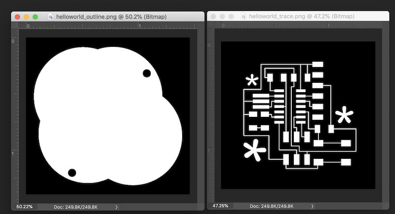
I exported the images and converted them into path for milling on Fab Module.
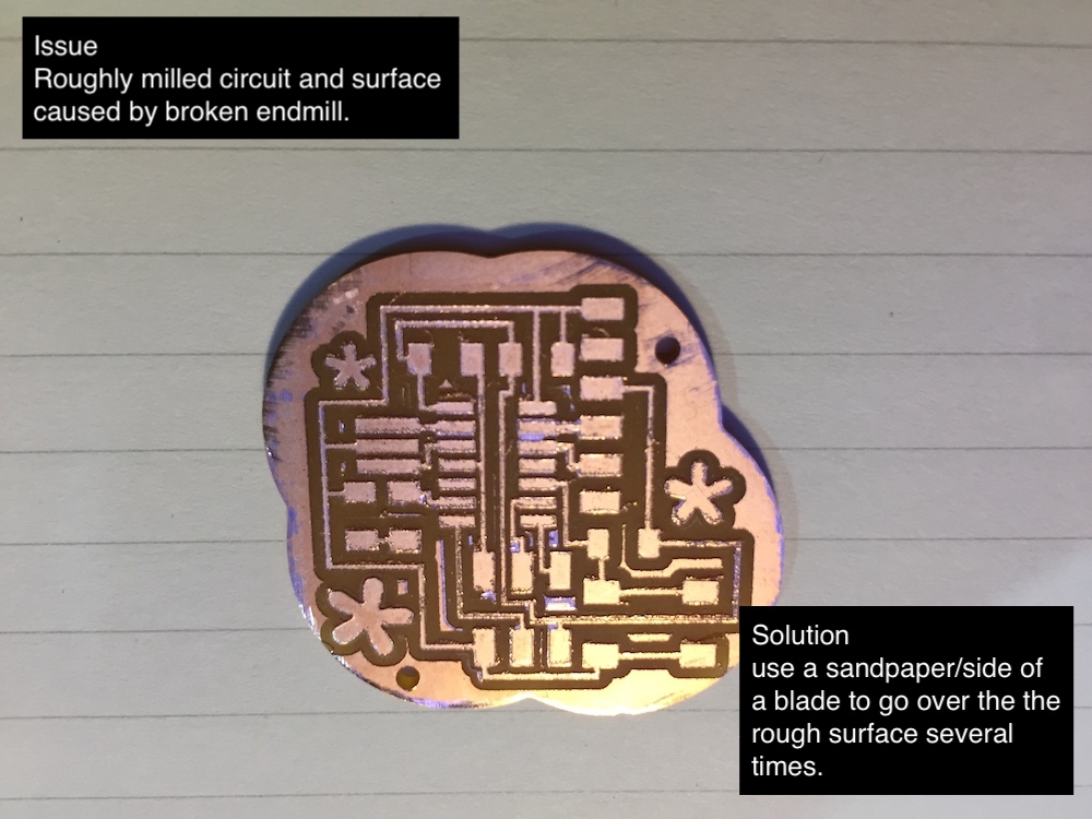
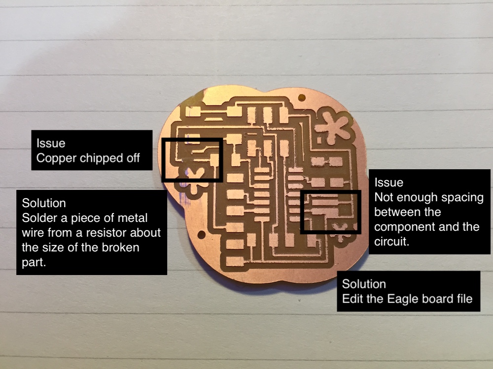
Milling
This week I have encountered a series of milling errors:
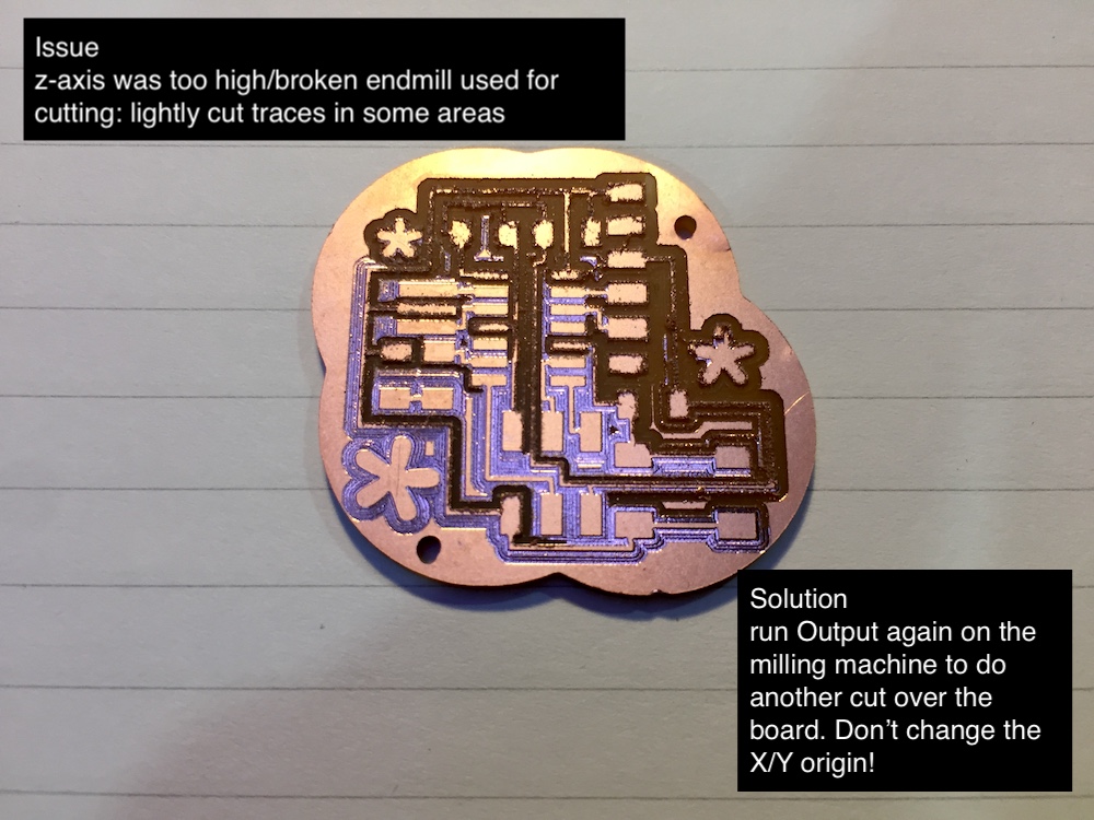
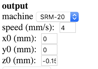
To avoid the same issue occur again, you can lower the z-axis in Fabmodule:
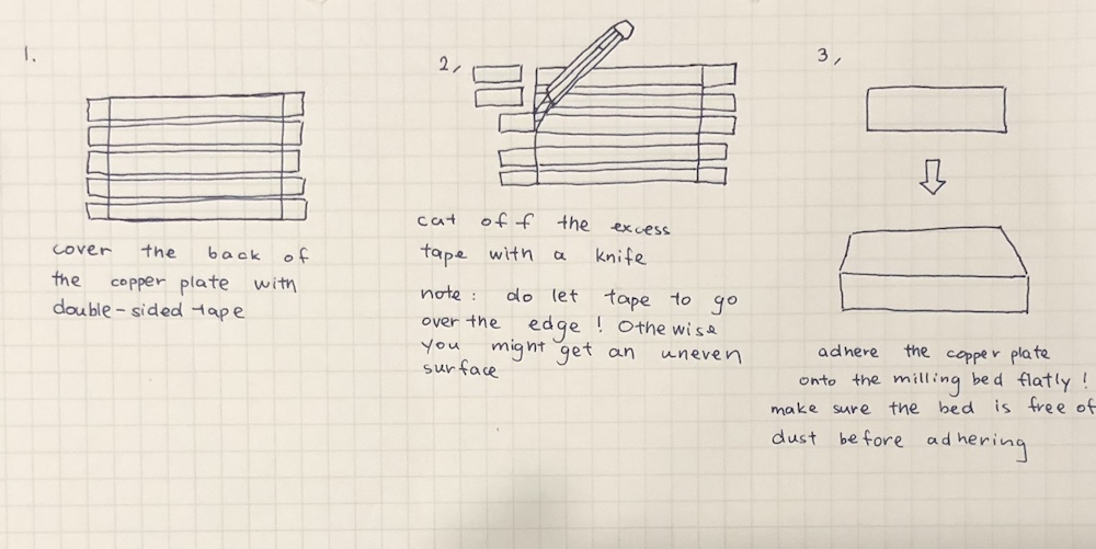
This problem is also likely caused by the copper plate not laying flat on the milling bed when adhering it onto the bed with double sided tape. The correct way of adhering the copper plate should be:
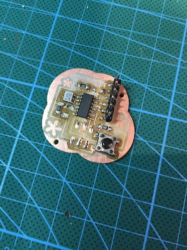
Soldering
Soldering was really difficult this week, especially with the button and the FTDI. It was difficult to level the components 90 degree with the board. I had to make sure the component lay flat before I solder. I also needed to figure out an order to solder that would minimize the contact between my solder iron and the ATtiny. Here is my practice round:
Here is the final PCB board:
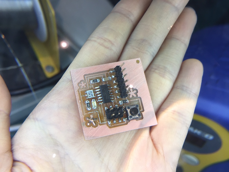
The final board ended being a square, because I reset my XY origin by accident while setting up Z origin for the outline cut. I measure the distance between the trace and the edge of the board, created a square shape as an outline, since it is a shape that is less likely to mismatch with the trace. Also, it was easier for me to remove from the milling bed after making too many mistakes in a week...
Programming
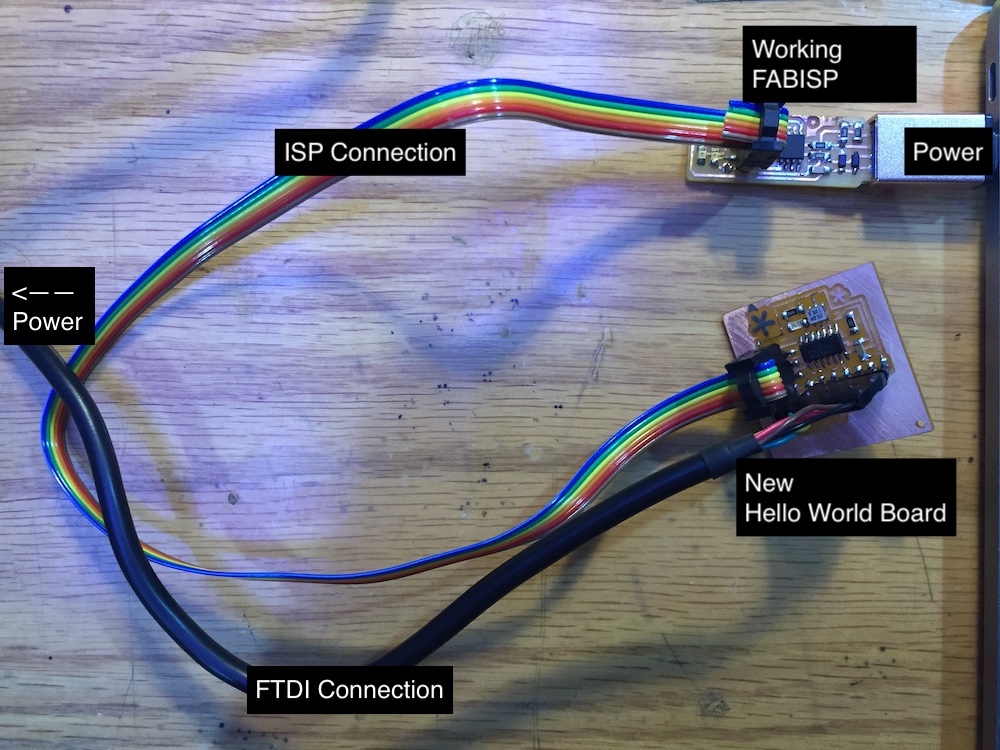
First, like in previous week, a working ISP is need to activate the new board I made. I used the FABISP I made two weeks ago. Here is the overview of the connection:
I downloaded hello.ftdi.44.echo.c (c language of the hello world) and hello.ftdi.44.echo.c.make (makefile for the program) made by Neil. Then in terminal, I opened the folder where I saved the files.
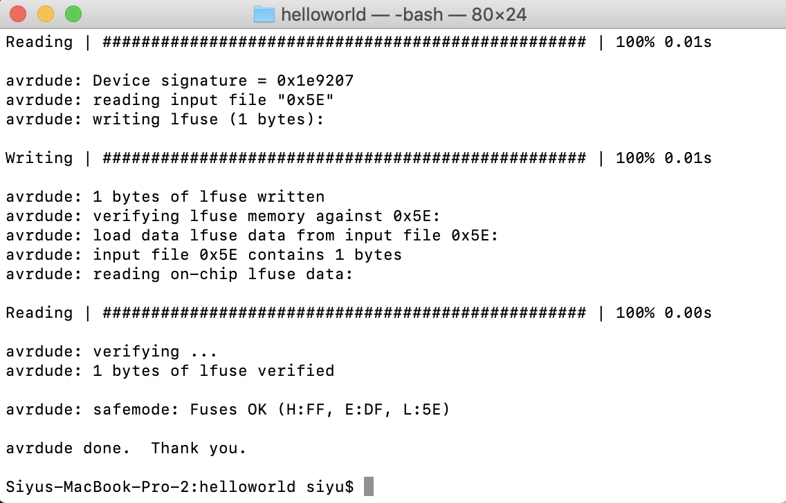
Here are the commands I ran in Terminal:
- make
- make program-usbtiny
- make program-usbtiny
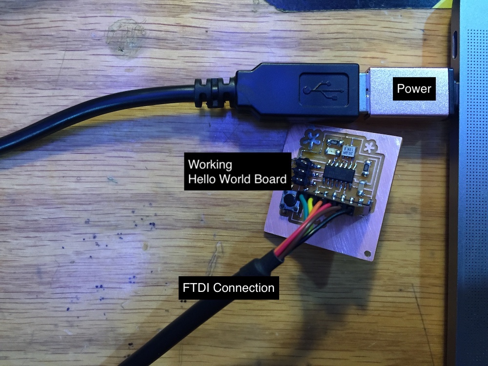
Then I disconnected the FabISP and reconnected the FTDI attached to the hello world board:
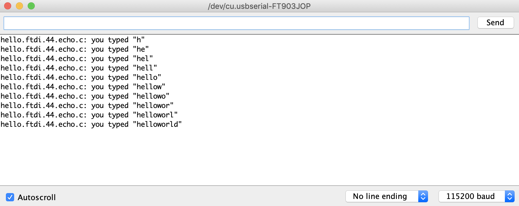
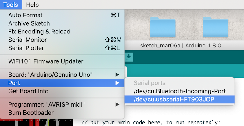
I ran the Hello World program in Arduino. First, make sure your board is selected under Port:
After, click on serial monitor.
You can begin to type “Hello World” letter-by -etter to Arduino! If your board is programed, it will echo back to you :)