Week 11: Output Devices
This week is a continuation of last week. First of all, SIYUno is finally working! The FTDI connection broke from the first board I made last week, so I made a new board.
Pulse Sensor
After Neil's lecture, I was really inspired, especially by the LED array boards. I aimed to use the Output Devices week to test out some devices that are relevant to my FINAL PROJECT. I wanted to test how a LED array would sync with pulse rate.
This is the code that came with the board I bought:
/*
>> Pulse Sensor Amped 1.2 <<
This code is for Pulse Sensor Amped by Joel Murphy and Yury Gitman
    www.pulsesensor.com
    >>> Pulse Sensor purple wire goes to Analog Pin 0 <<<
Pulse Sensor sample aquisition and processing happens in the background via Timer 2 interrupt. 2mS sample rate.
PWM on pins 3 and 11 will not work when using this code, because we are using Timer 2!
The following variables are automatically updated:
Signal :    int that holds the analog signal data straight from the sensor. updated every 2mS.
IBI  :      int that holds the time interval between beats. 2mS resolution.
BPM  :      int that holds the heart rate value, derived every beat, from averaging previous 10 IBI values.
QS  :       boolean that is made true whenever Pulse is found and BPM is updated. User must reset.
Pulse :     boolean that is true when a heartbeat is sensed then false in time with pin13 LED going out.

This code is designed with output serial data to Processing sketch "PulseSensorAmped_Processing-xx"
The Processing sketch is a simple data visualizer.
All the work to find the heartbeat and determine the heartrate happens in the code below.
Pin 13 LED will blink with heartbeat.
If you want to use pin 13 for something else, adjust the interrupt handler
It will also fade an LED on pin fadePin with every beat. Put an LED and series resistor from fadePin to GND.
Check here for detailed code walkthrough:
http://pulsesensor.myshopify.com/pages/pulse-sensor-amped-arduino-v1dot1

Code Version 1.2 by Joel Murphy & Yury Gitman  Spring 2013
This update fixes the firstBeat and secondBeat flag usage so that realistic BPM is reported.

*/


//  VARIABLES
int pulsePin = 14;                 // Pulse Sensor purple wire connected to analog pin 0
int blinkPin = 13;                // pin to blink led at each beat
int fadePin = 5;                  // pin to do fancy classy fading blink at each beat
int fadeRate = 0;                 // used to fade LED on with PWM on fadePin


// these variables are volatile because they are used during the interrupt service routine!
volatile int BPM;                   // used to hold the pulse rate
volatile int Signal;                // holds the incoming raw data
volatile int IBI = 600;             // holds the time between beats, must be seeded!
volatile boolean Pulse = false;     // true when pulse wave is high, false when it's low
volatile boolean QS = false;        // becomes true when Arduoino finds a beat.


void setup(){
  pinMode(blinkPin,OUTPUT);         // pin that will blink to your heartbeat!
  pinMode(fadePin,OUTPUT);          // pin that will fade to your heartbeat!
  Serial.begin(9600);             // we agree to talk fast!
  interruptSetup();                 // sets up to read Pulse Sensor signal every 2mS
   // UN-COMMENT THE NEXT LINE IF YOU ARE POWERING The Pulse Sensor AT LOW VOLTAGE,
   // AND APPLY THAT VOLTAGE TO THE A-REF PIN
   //analogReference(EXTERNAL);
}


void loop(){
  sendDataToProcessing('S', Signal);     // send Processing the raw Pulse Sensor data
  if (QS == true){                       // Quantified Self flag is true when arduino finds a heartbeat
        fadeRate = 255;                  // Set 'fadeRate' Variable to 255 to fade LED with pulse
        sendDataToProcessing('B',BPM);   // send heart rate with a 'B' prefix
        sendDataToProcessing('Q',IBI);   // send time between beats with a 'Q' prefix
        QS = false;                      // reset the Quantified Self flag for next time
     }

  ledFadeToBeat();

  delay(20);                             //  take a break
}


void ledFadeToBeat(){
    fadeRate -= 15;                         //  set LED fade value
    fadeRate = constrain(fadeRate,0,255);   //  keep LED fade value from going into negative numbers!
    analogWrite(fadePin,fadeRate);          //  fade LED
  }


void sendDataToProcessing(char symbol, int data ){
    Serial.print(symbol);                // symbol prefix tells Processing what type of data is coming
    Serial.println(data);                // the data to send culminating in a carriage return
  }
LEDssssssssssssss!
I was fascinated by the LED array board from Neil and could not wait till making the board, but I was immediately confused by the logic behind the Neil board. Then I tried to look through boards made by some past students, either was a recreation of a Neil board or a board that I did not have the brain capacity to understand… :( which began my series of mistakes this week. But before talking about the mistakes, I will mention the logic behind LED Array using Charlieplexing that I understood better after watching THIS VIDEO by Brian Lough.
Just as a recap, LED stands for light-emitted diodes. As diodes, LED will only allow current to follow in one direction. The positive side of a LED is called the anodes and the negative side is called the cathodes. A resistor is needed in between the power source and the LED, since too much current can burn the LED *OOOOOOO*
What is Charlieplexing?!
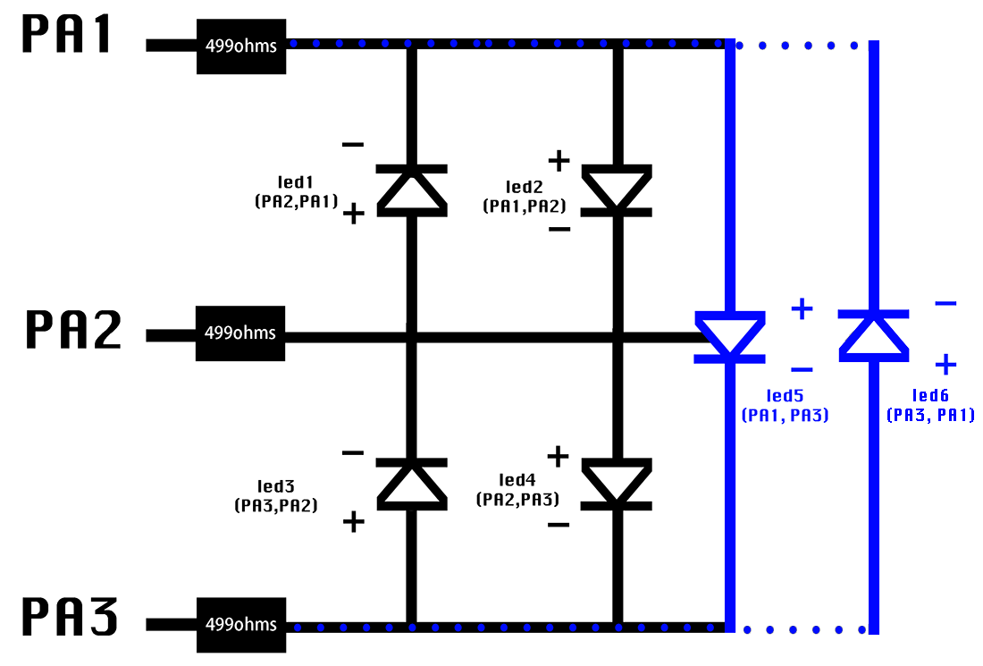
Charlieplexing is a way of controlling LEDs individually using a limited number of pins. You can place one LED in between two pins on a microcontroller as either the positive and negative side for the individual LED. For example, you can have two LED in between pin 2 and pin 3, with one that uses pin 2 as the positive and pin 3 as the negative, another one that uses pin 3 as the positive and pin 2 as the negative. This formula “N(N-1)” (NOTE:N is the amount) gives you the number of LEDs you can have with the amount of pins you are using. The chart below illustrates six LEDs controlled by three pins. Later when writing the program in Arduino, individual name will be given to each LED. Each LED would be tagged as (positive pin, negative pin). For example, LED1 in the chart uses PA2 as the positive and PA1 as negative, it is tagged as (PA2, PA1).
Round One: FAILED!
However, I did not sat down reading enough about Charlieplexing at first. I started by studying Neil’s board and past student’s schematics, but it was impossible for me to fully understand the board from the visuals. Then, I tried to imitate one of the past student’s schematics, which began my series of mistakes this week. As a visual thinker, I have the tendency of over-relying on diagrams. In electronic design, you MUST FULLY understand the principle behind your board in order to customize and to make things work!!!!! I really learnt my lesson D:::::::; Anyway, here is my work log from round one.
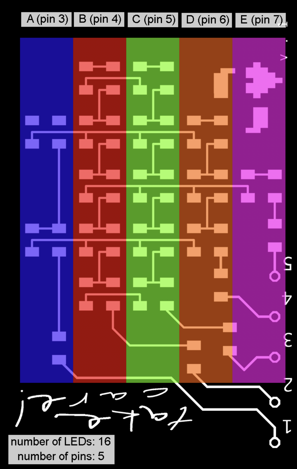
Based off my final project, I was planning to make a 16-LED-board like this:
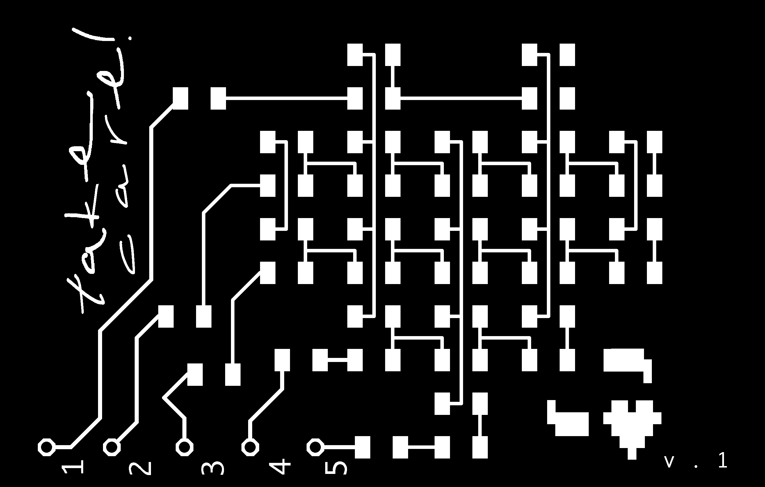
I looked at THIS past student’s board and liked how the student just included the male pin headers for connected the LED array board onto another micro controller board, which gives me a lot of flexibility for placing the LED board on wearables. The schematics from the student looked really nice and clean (BUT THAT IS NOT IMPORTANT IN ELECTRONIC DESIGN), which was easy for me to imitate. Here are images that show my failed process in Eagle.
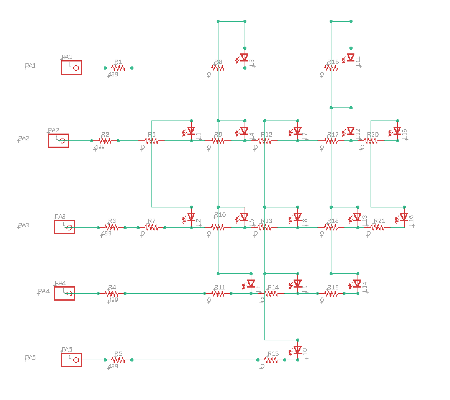
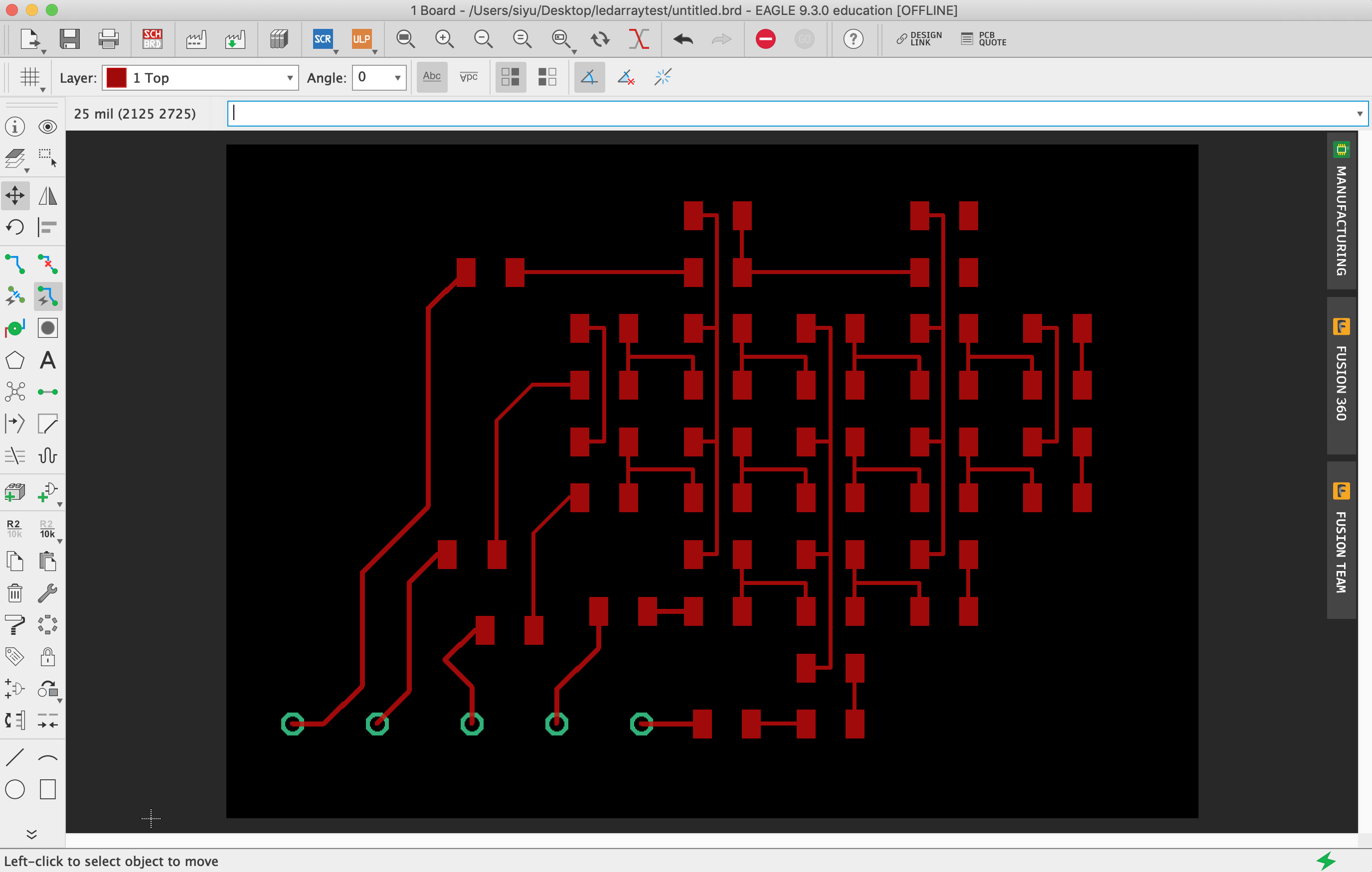
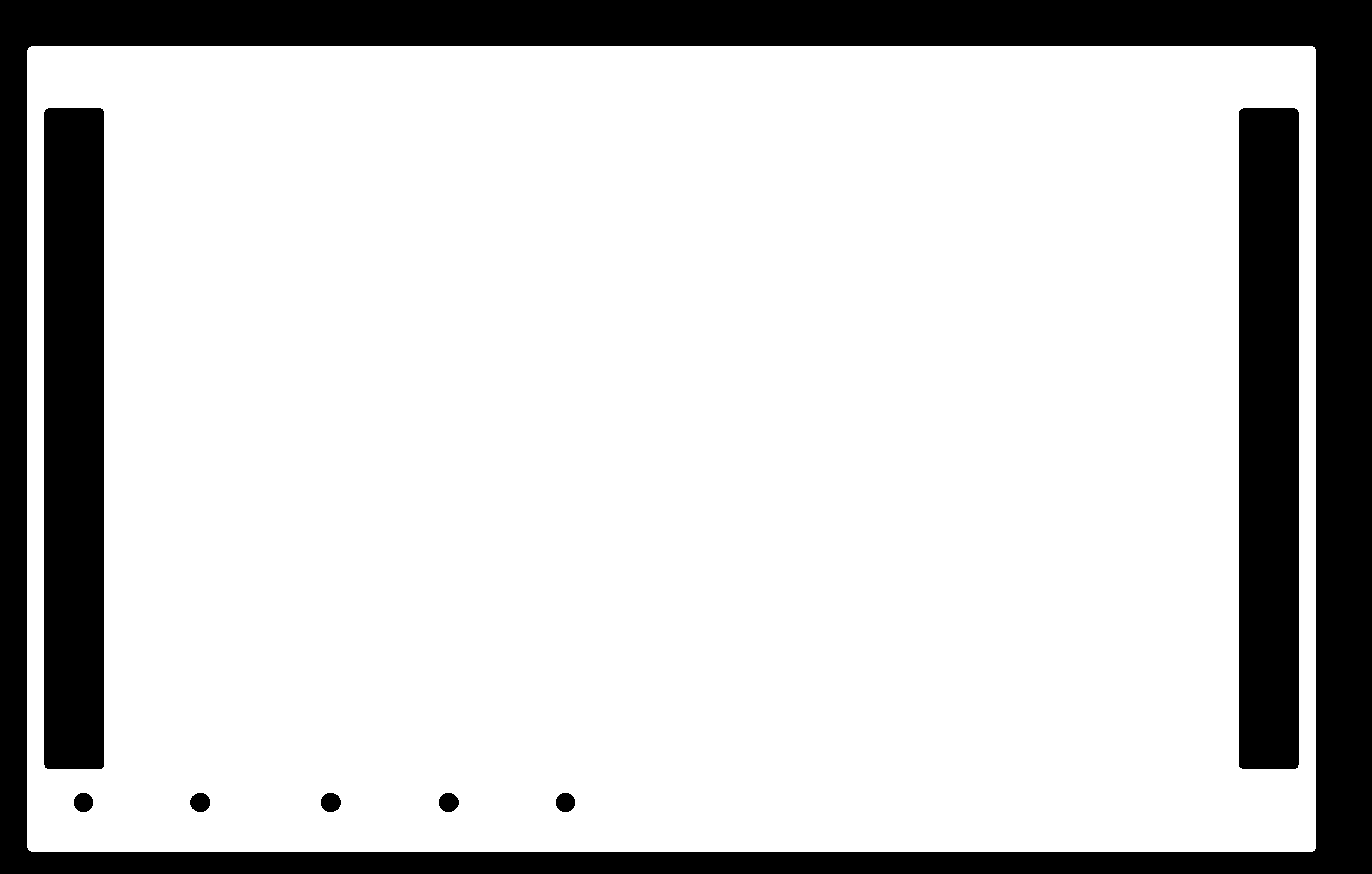
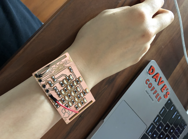
Then I added some graphics to the board in Photoshop. In the outline file, I also added two openings for placing a strap to make the board wearable:
The board looked really nice, but it is not working :(
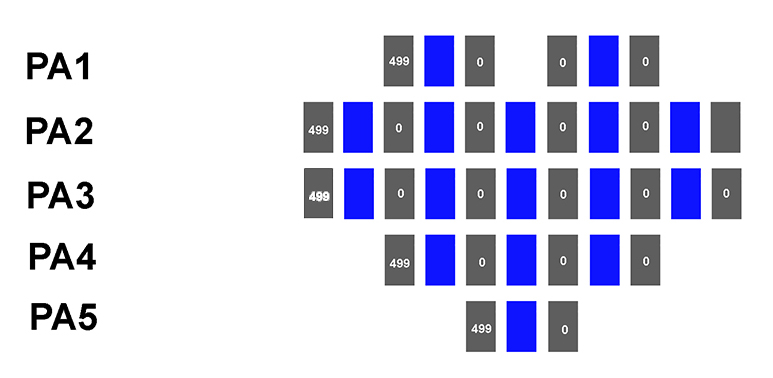
This chart below illustrates the logic I have followed in making my board, which is far from the theory of electronics and Charlieplexing. In my mind, I was breaking down a LED array board visually by thinking about my component as grid. But this is not how the Charlieplexing schematic works. PLEASE DO NOT IMITATE ME!
Round Two: WORK IN PROGRESS - - - - - -> WORKING!!!!
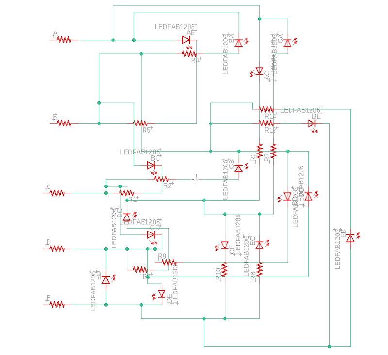
I stood back for a minute without thinking about how my board would look like, even though my final result is highly visual. Learnt my lessons from round one and studied some basic principles more in depth, I made a drawing before making the schematic in Eagle:
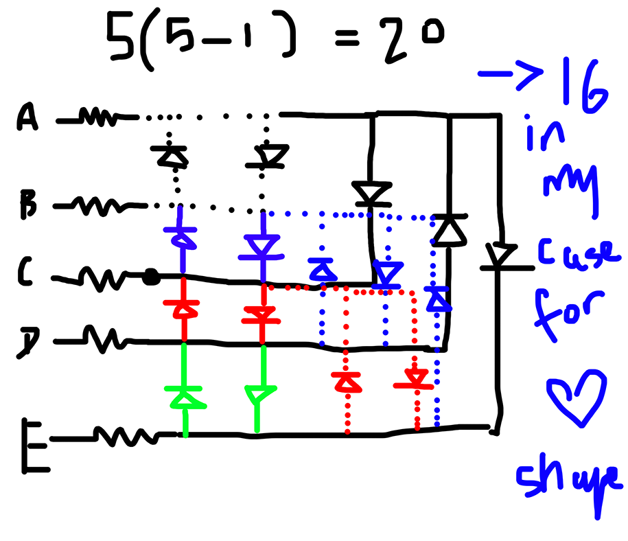
I would also need to add 0ohm resistors as jumpers. For example, if an LED needs positive from A and negative from D, it is likely to touch other wires when trying to reach either of the side. A 0ohm resistor bridges the LED with a positive or a negative side by crossing over another trace (NOTE: a trace can travel through a resistor).
On the schematic, my classmate Flavie suggested me to place the LED first, and only add 0ohm resistor when the wire is stuck.
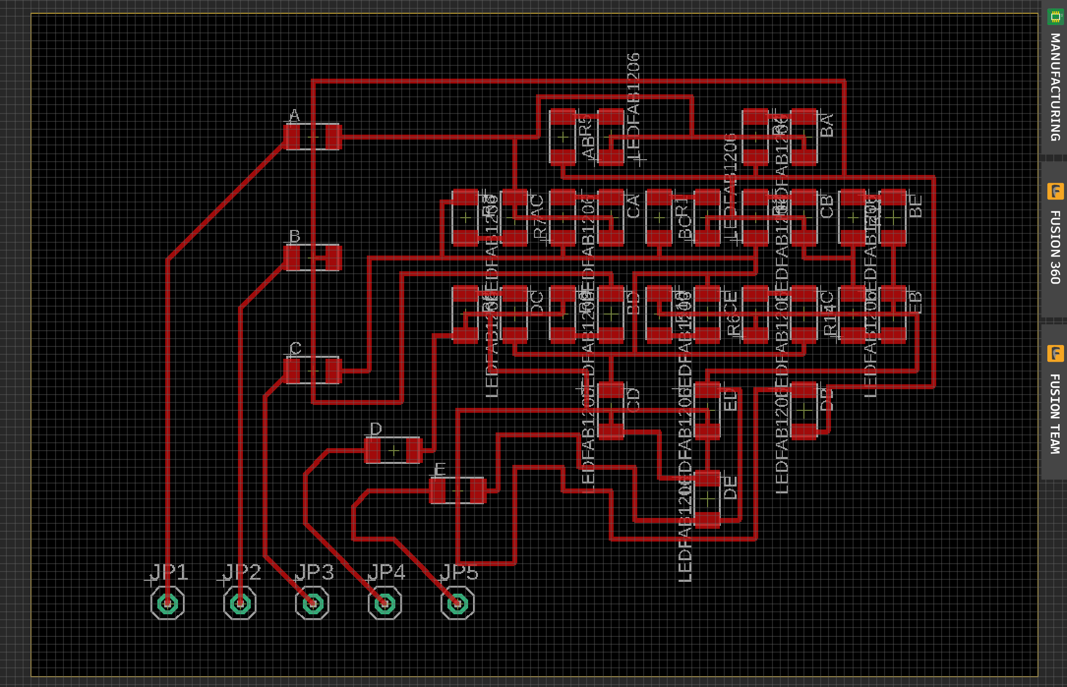
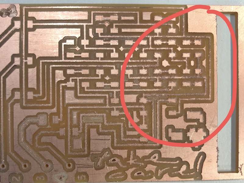
Since I made my wire width 14 this time, in fab module some parts had the risk of blending. I went back to modified these parts. Also, to use up the remaining space on the copper sheey in the milling machine, I flipped my traces 90 degree.
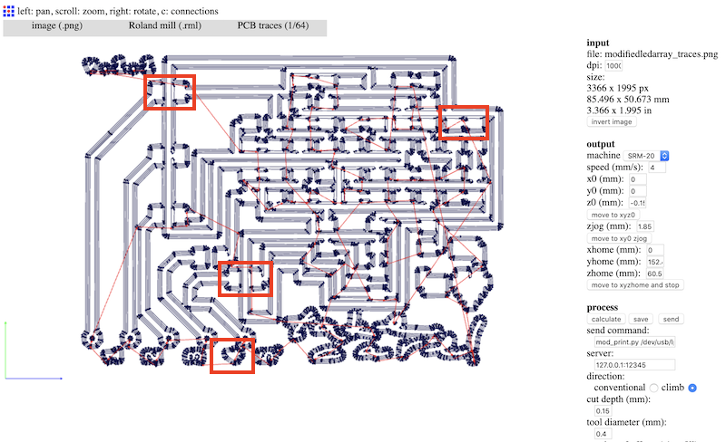
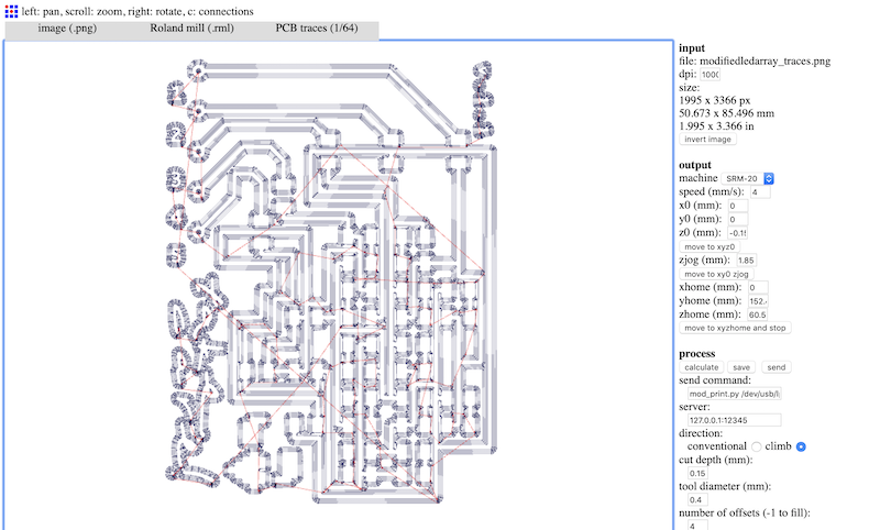
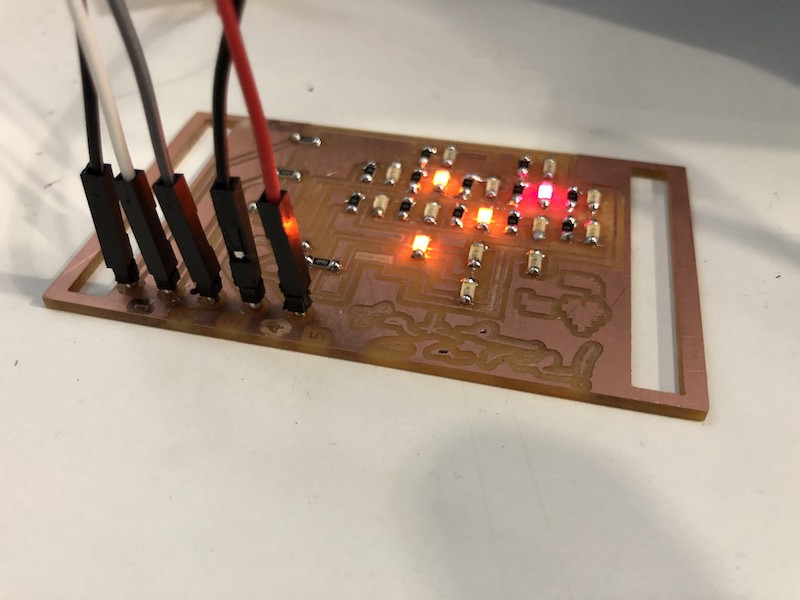
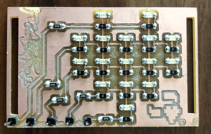
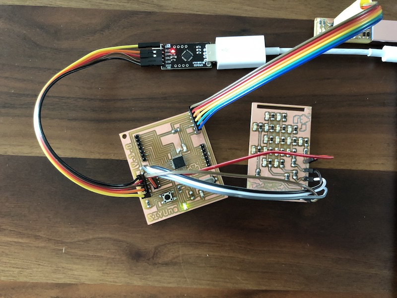
Here is the pcb board for the second round:
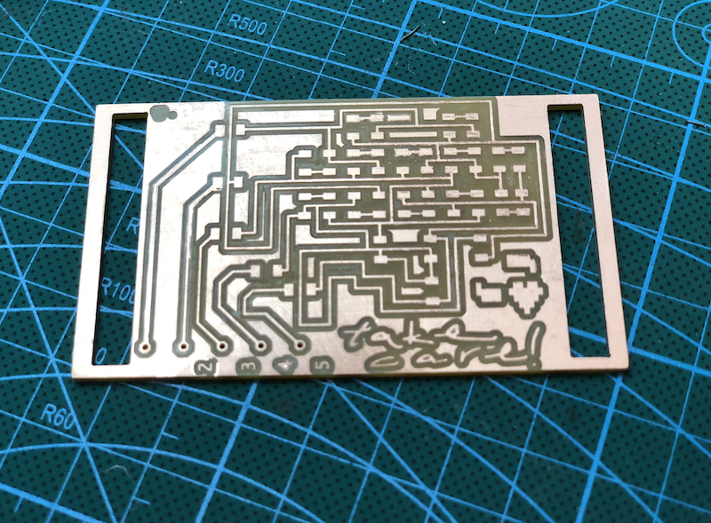
NOTE TO SELF: when there are circuits that look like broken wires, use the side of a blade to go over them like how you use a sheet of sand paper.
When soldering, make sure to check the polarity of LED according to the direction of the LED on the circuit. It is really helpful to have a multimeter handy, so you can always check if the LED is getting the right positive and negative sides on the board. I would suggest to check the LED connection every time after you solder one, then you do not need to desolder a huge amount of LED at the end...
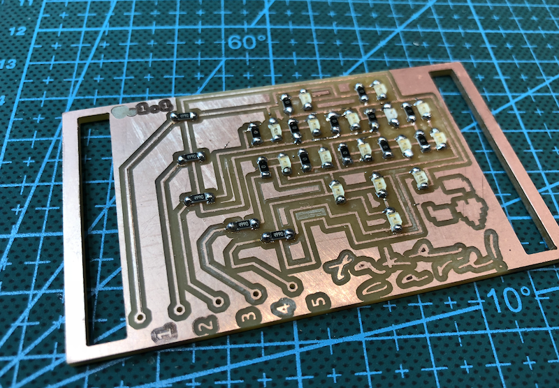
THE LED IS FINALLY WORKING YAH!!!!!! *WWW*
Here is the code I have used. I referred to THIS student's code to check whether the board is working, since I ran out of time to write a Charlieplexing code from scratch:
int led1 = 8;
int led2 = 4;
int led3 = 5;
int led4 = 6;
int led5 = 7;

void setup(){
  pinMode(led1,OUTPUT);
  pinMode(led2,OUTPUT);
  pinMode(led3,OUTPUT);
  pinMode(led4,OUTPUT);
  pinMode(led5,OUTPUT);

}

void loop(){
  digitalWrite(led1,HIGH);
  digitalWrite(led2,LOW);
  digitalWrite(led3,LOW);
  digitalWrite(led4,LOW);
  digitalWrite(led5,LOW);
  delay(100);
  digitalWrite(led1,LOW);
  digitalWrite(led2,HIGH);
  digitalWrite(led3,LOW);
  digitalWrite(led4,LOW);
  digitalWrite(led5,LOW);
  delay(100);
  digitalWrite(led1,LOW);
  digitalWrite(led2,LOW);
  digitalWrite(led3,HIGH);
  digitalWrite(led4,LOW);
  digitalWrite(led5,LOW);
  delay(100);
  digitalWrite(led1,LOW);
  digitalWrite(led2,LOW);
  digitalWrite(led3,LOW);
  digitalWrite(led4,HIGH);
  digitalWrite(led5,LOW);
  delay(100);
  digitalWrite(led1,LOW);
  digitalWrite(led2,LOW);
  digitalWrite(led3,LOW);
  digitalWrite(led4,LOW);
  digitalWrite(led5,HIGH);
  delay(100);
}