15/ interface and application programming
This week we need to write an application that interfaces with an input or output device that we make. I tried using Arduino(FLAVINO) with:
1. processing
2. Max/Msp
← previous
→ next
⋯ assignment list
🏁/ final project
Drawing with push buttons in processing
For communication between processing and arduino, Firmata protocol is necessary. "Firmata is a protocol for communicating with microcontrollers from software on a computer." The Firmata protocol can be implemented in any microcontroller platform, such as Arduino. "This allows you to write custom firmware without having to create your own protocol and objects for the programming environment that you are using."
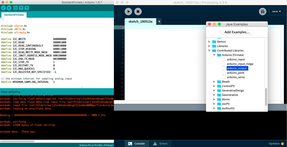
In order to form the communication, I need to install firmata library for both Arduino and processing. In arduino IDE, open the standaredFirmata example file, directly upload it to the MCU. In processing, open the arduino input or output example file and start modify sketch.
I tried push buttons as input devices and used them to draw dots in processing. The left and middle buttons were used to draw dots at certain column position, and the right button is used to switch to the next row.
One thing I haven't figure out is how to add deboucing for button in processing. As it is shown in the video, the vertical space is not always even because the "y += 5" increasing command is executed many times depend on how long the button is pressed, which is different from time to time.
So far the code looks like this:
import processing.serial.*;
import cc.arduino.*;

Arduino arduino;

int x = 20;
int y = 20;

void setup() {
  size(200,700);
  background(255);

  println(Arduino.list());
  arduino = new Arduino(this, Arduino.list()[1], 57600);

  for (int i = 2; i <= 4; i++)
    arduino.pinMode(i, Arduino.INPUT);
}

void draw() {
  fill(0);

  if (arduino.digitalRead(2) == Arduino.HIGH){
    ellipse(20,y,10,10);
  }

  if (arduino.digitalRead(3) == Arduino.HIGH){
    ellipse(50,y,10,10);
  }

  if (arduino.digitalRead(4) == Arduino.HIGH ){
    y += 5;
    println(y);
  }
}
Communication between Max and Arduino
"Max, also known as Max/MSP/Jitter, is a visual programming language for music and multimedia that helps you build complex, interactive programs with no need for coding." Max can communicate with Arduino using serial communication.
I tried using Max to control Arduino. I followed this MAX msp 7: Passing data from Max to Arduino tutorial to send signal to LED on FLAVINO in Max.
The next step is to figure out how to output Max/Jitter graphics to an OLED screen :/
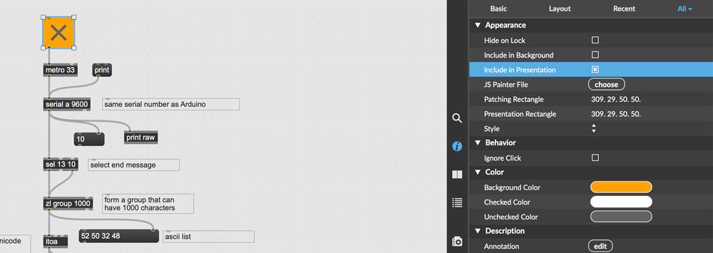
It is more imteresting to have Arduino input to control sound or graphics in Max. I followed this MAX msp 7: Sending data from arduino into Max tutorial on youtube to set up the communication. This image below is exactly the workflow from the tutorial.

I then modified a previously made drum machine patch and added the button control using Arduino. Now the left and middle buttons on the bread board each has got its own sound, and the right button is pressed to switch from playing the sequence forward or backward.
My next step was to add two potentiometers to control the frequency of sound waves.
Below is the Arduino IDE code:
const int buttonPin = 2;
const int buttonPin2 = 3;
const int buttonPin3 = A3;

int buttonState = 0;
int buttonState2 = 0;
int buttonState3 = 0;

int lastButtonState = 0;
int lastButtonState2 = 0;
int lastButtonState3 = 0;

int potpin = A0;
int potpin2 = A2;
int degree = 0;
int degree2 = 0;
int potvalue = 0;
int potvalue2 = 0;

void setup() {
  pinMode(buttonPin, INPUT);
  pinMode(buttonPin2, INPUT);
  pinMode(buttonPin3, INPUT);

  pinMode(potpin,INPUT);
  pinMode(potpin2,INPUT);
  delay(1000);
  Serial.begin(9600);
}

void loop() {
  potvalue = analogRead(potpin);
  potvalue2 = analogRead(potpin2);
  degree = map(potvalue, 0, 1023, 0, 255);
  degree2 = map(potvalue2, 0, 1023, 0, 255);

  Serial.print(degree);
  Serial.print(" ");
  Serial.println(degree2);
  delay(100);

  buttonState = digitalRead(buttonPin);
  buttonState2 = digitalRead(buttonPin2);
  buttonState3 = digitalRead(buttonPin3);

  if (buttonState != lastButtonState){
    if (buttonState == HIGH){
    }else{
      Serial.println(2000);
    }
    //in case of bounce
    delay(50);
  }
  lastButtonState = buttonState;

  if (buttonState2 != lastButtonState2){
    if (buttonState2 == HIGH){
    }else{
      Serial.println(3000);
    }
    delay(50);
  }
  lastButtonState2 = buttonState2;

   if (buttonState3 != lastButtonState3){
    if (buttonState3 == HIGH){
    }else{
      Serial.println(4000);
    }
    delay(50);
  }
  lastButtonState3 = buttonState3;
}
Later I watched some other tutorials explaining the presentation mode in Max and how to export a stand-alone application from it.
In the editting mode, select the components you want to include in the presentation mode and check the "include in presentation" box in the inspector. In my case, I need to have the Serial communication speed part in the presentation, otherwise the exported app will not talk to Arduino.
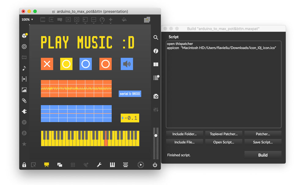
Arrange layout in presentation mode, customize the look, resize Max window size to your future application window size, choose build application from menu bar > add app icon image if you want > build > choose save location > file type choose application > done!
This is how the desktop app work with potentiometer and button input from Arduino:
For my further reference, this PPT explains ASCII byte number, may help me understand the data communication.
(Updated 05.15.2019)