Electronic Design
For this week’s assignment, we had to use the test equipment in your lab to observe the operation of a microcontroller circuit board.
We used an oscilloscope and a multimeter.
What is an oscilloscope ?
An oscilloscope is a laboratory instrument commonly used to display and analyze the waveform of electronic signals. In effect, the device draws a graph of the instantaneous signal voltage as a function of time.
In any oscilloscope, the horizontal sweep is measured in seconds per division (s/div), milliseconds per division (ms/div), microseconds per division (s/div), or nanoseconds per division (ns/div).
The vertical deflection is measured in volts per division (V/div), millivolts per division (mV/div), or microvolts per division (μV/div).
Virtually all oscilloscopes have adjustable horizontal sweep and vertical deflection settings.
The illustration shows two common waveforms as they might appear when displayed on an oscilloscope screen. The signal on the top is a sine wave; the signal on the bottom is a ramp wave.
What we expected to see ?
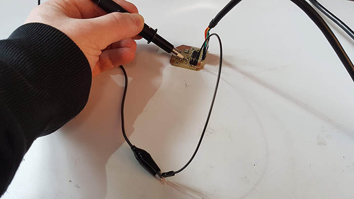
We are sending a blink program. The microcontroller (ATtiny44) should send a square signal, that corresponds to low and high. In our case 0V coresspond to 0 (LOW) and 5V coresspond to 1 (HIGH) We plugged a co-axial cable to the oscilloscope, and a probe to the board (between GND and the PIN sending the signal, here it’s the PB3).
We set the oscilloscope using the horizontal and vertical scales. It allows to change the time and amplitude by unit.
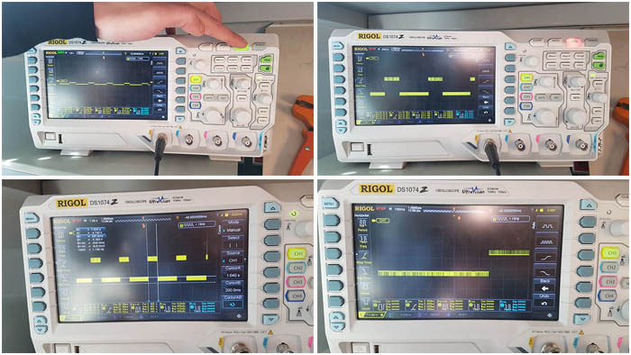
What actually saw ?
At the moment where the signal is supposed to be perfectly constant, we can see that it keeps oscillating. It’s really hard to have a continuous signal, even if periods between high and low should be identical. The signal is not identical but it repeats itself periodically.
We observed that the microcontroller sends a HIGH signal during 1660 milliseconds. It sends the LOW signal during 820 milliseconds.
Possible reason why we obtain those results ? In the making of the board, the external clock was not precisely set up so that may be one of the possible reasons we have no precise results on the oscilloscope.
What is a multimeter ?
A multimeter is an electronic tool used to measure voltage, amps and resistance across circuits. By attaching two leads to different parts of an electrical system, we can use multimeters to detect levels of voltage and resistance, or changes in electrical currents.
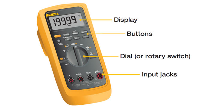
This tool may also be known as a volt-ohm meter or volt-ohm-milliammeter (VOM).
What we expected to see ?
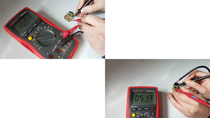
We chose to examine the voltage transmitted by the led, between the VCC and the GND pins and the differents resistors. The board is powered in 5V, then we should see a voltage beetwen VCC and GND about 5V.
For the resistor, the multimeter passes a current with precise tension through a resistance and check the voltage out. And it calcul the amount of the resistor using R = U / I
What we actually saw ?
The led : oscillates between 2V et 0V
Between VCC and GND : 5.13V
The resistor :
10k