Networking and Communication
- Group: Send a message between two projects (assignments made by different students.
- Individual assignment: Design, build, and connect wired or wireless node(s) with network or bus addresses
Group Assigment - Networking
Students:
- Silvia Lugo
- Carlos Nina
- Ivan Callupe
- Diego Santa Cruz
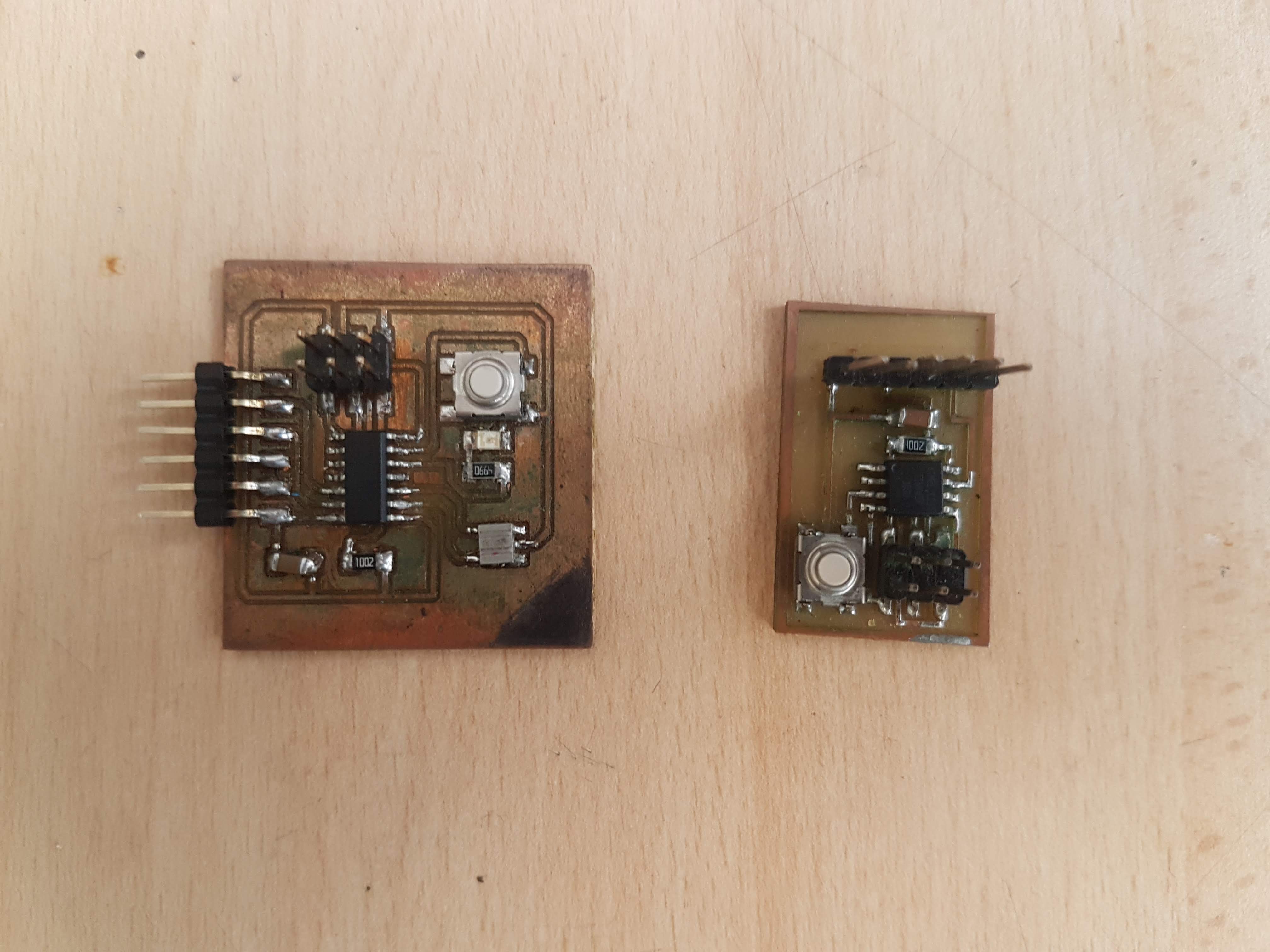
For this assigment we used Carlos and my board to communicate. Using Software Serial we will sending signal through a button push. Code for this next:
Code for this next:
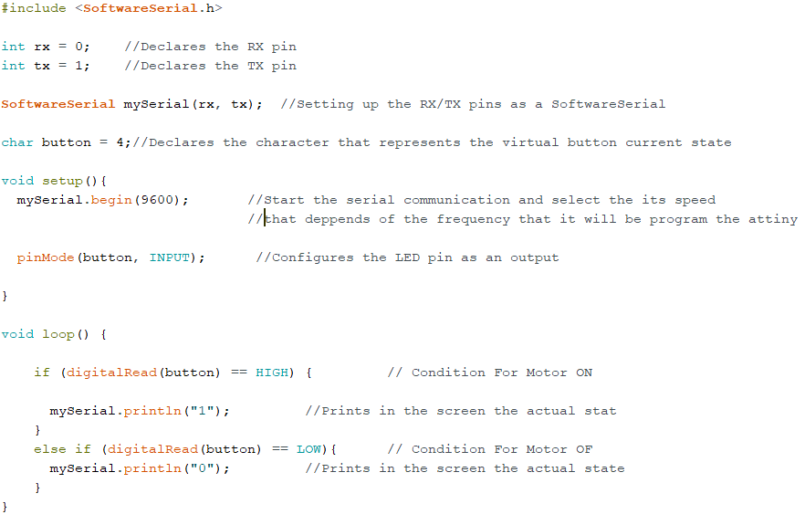
Button board code:
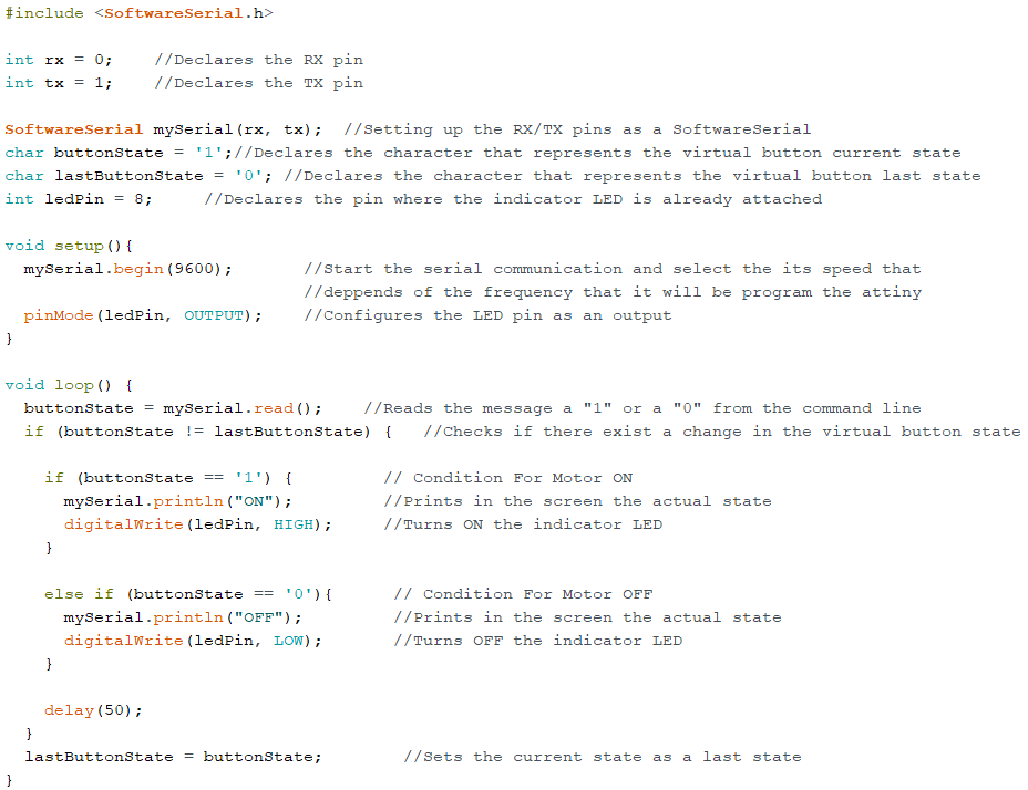
LED board code:
We set the Arduino IDE parameters for using it as a programmer. This parameters are for a Attin44 microcontroller:
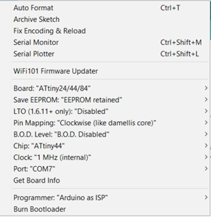
Now the parameters for a Attiny45 microcontroller:
Once burned, we test it. We are using a Arduino One board to power it:
It works!
Design Network
I will be using 2 boards from previous weeks to send data and turn a led in the other one. Board from week 11 (Input) will send either 1 or 0 and the other board will turned on/off depending of the value.
The code will make the board to turn both LEDs at different times when button is pushed.
Coding
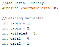
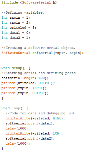
First I will code the OUTPUT. Attiny45 do not have hardware serial comm, instead software based will be used. SoftwareSerial library allows tiny and arduino boards to create extra serial pins so, we are adding to the code.
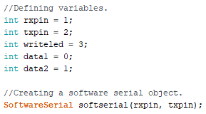
Defining some variables and creating the SoftwareSerial object which will be called "softserial". This object need the values for virtual Rx and Tx.
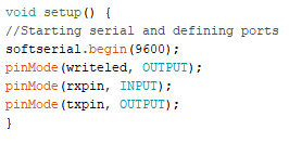
In "setup" function, "softserial" starts with the begin method and some ports are defined as input/output.
Finally the "loop" code is added. Here a LED is turned on/off for debugging purpose and 0 and 1 bytes are sent through Tx pin.
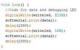
In the end the code seems like this:
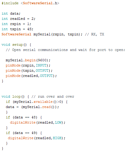
Coding the input
Including librar, variables and opening the serial comm it's similar.
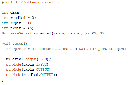
In "loop" thing changes because now it is reading data.
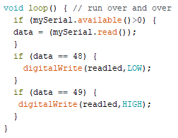
Finally the code looks like this:
Testing
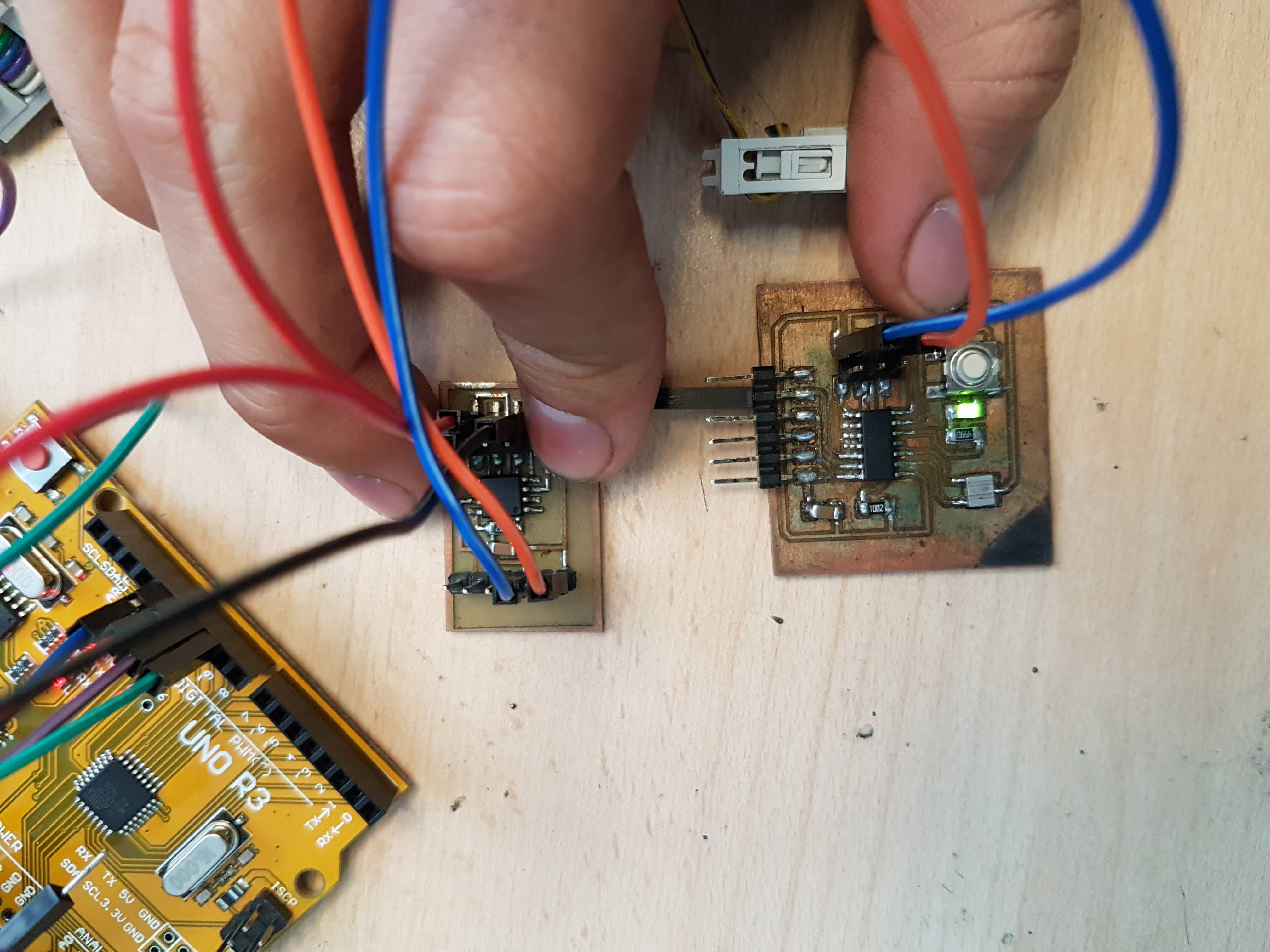
Using an arduino board for power feeding, I connect it to the output board and from it, serial connect the other board. Video show data send from one and the other recieving.
Create project, schematics and add all components to it. This time, I tried to make less "physical" connections but more labeled ones. Once all is connected, we start board design.