Eleventh assignment
27 March 2019
Week's assignment
This weeks assignment was measure something: add a sensor to a micro-controller board that I have designed and read it.
This time I decided to use a LDR I am going to be trying first how it works and see if I can use a board I already have to make it work, and after that I am designing a new PCB with the LDR included.
input
LDR
A Light Dependent Resistor or a Photoresistor is an electronic component that has a resistance that varies depending of the light intensity.
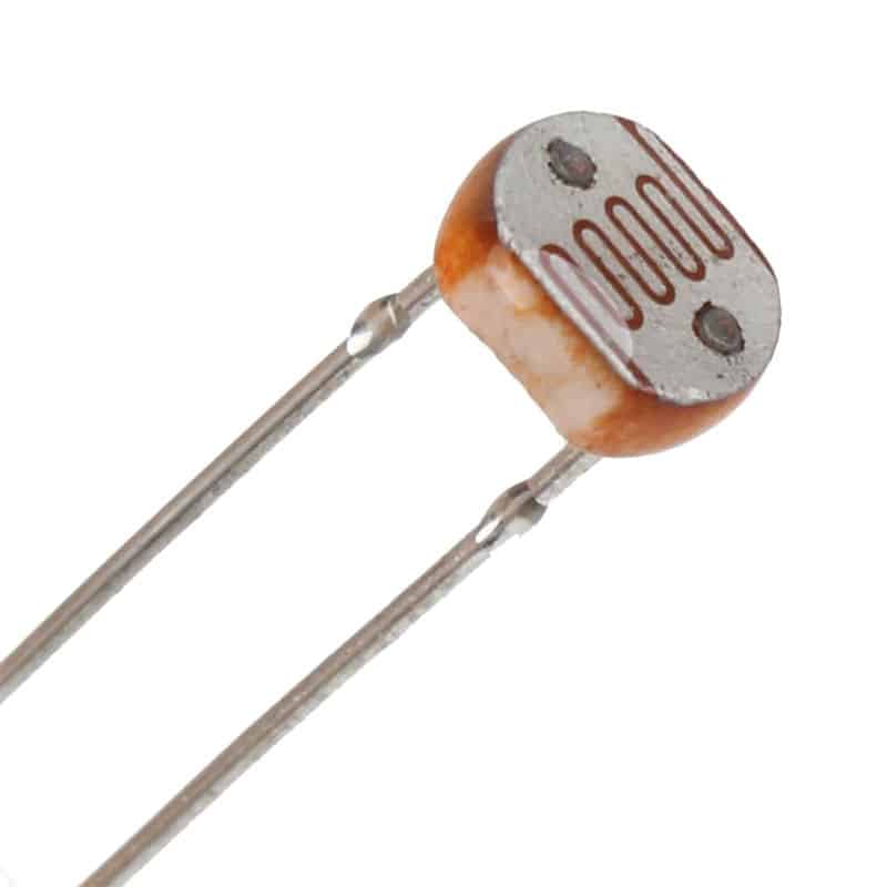
How does it work?
When in darkness the resistance goes up almost as high as 1MΩ, but when light falls on the LDR, the resistance falls down to a few KΩ
You can also check the Datasheet.
It could be very useful in a turn ON and OFF device depending on the ambient light, so that is what we are doing for this week.
ATTINY44
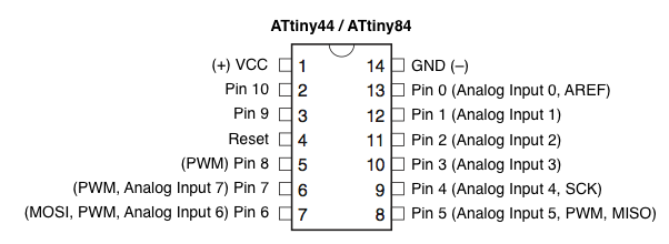
PINOUT
To program the ATtiny 44 there are 6 of the 14 pins that are used.
Three of these pins are the ones we use to program the chip and are known as SPI (Serial Peripheral Interface). These are the pins:
MISO (Master In - Slave Out)
MOSI (Master Out - Slave In)
SCK (Serial ClocK)
The "master" is the ISP you are using to program and the "slave" is the chip being programmed
The other three pins that we use for programming:
VCC
GND
RESET
INPUT
I needed to check for this board if the microcontroller still had some pins left that I could use to connect a sensor.
I had PA0 and PA1 connected to FTDI header's TX and RX respectively. And checking the pinout diagram, those are Analog Input pins, which means that are perfect for what we need to do this week
Programming with Arduino
Arduino nano
I'm goint to be using an arduino nano

First thing to do is open the Arduino software in the computer and connect the Arduino Nano to it.
If you don't have installed the support for ATtiny in your arduino you may copy this link in the board's manager: http://drazzy.com/package_drazzy.com_index.json
You can see more detail on how to do this on my Embedded programming's week page.
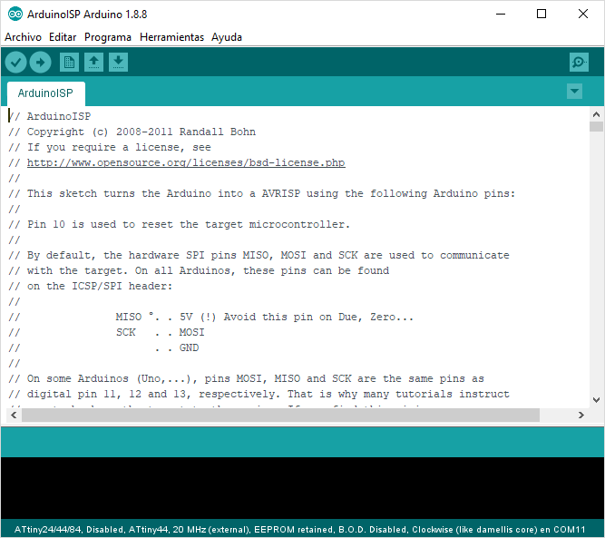
Now we should set the Arduino as an ISP. For this we should just go to File > Example > ArduinoISP.
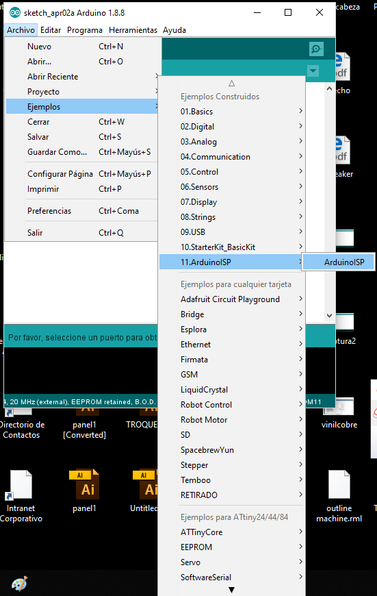
A new sketch window should have opened, and we just need to upload it to the Arduino nano.
Making the connections
What we need for programming the ATtiny:
Arduino nano
ATtiny 44
Breadboard
Insulated Jumper cables
10 µF Capacitor
Connecting the ATtiny
To program any ATtiny microcontroller we connect the six pins i mentioned before, but to program our board (until now) we normally use the ISP/SPI header.
This ISP has 6 pins which means 6 connections, as I don't have an ISP cable I will connect 6 jumper wires.
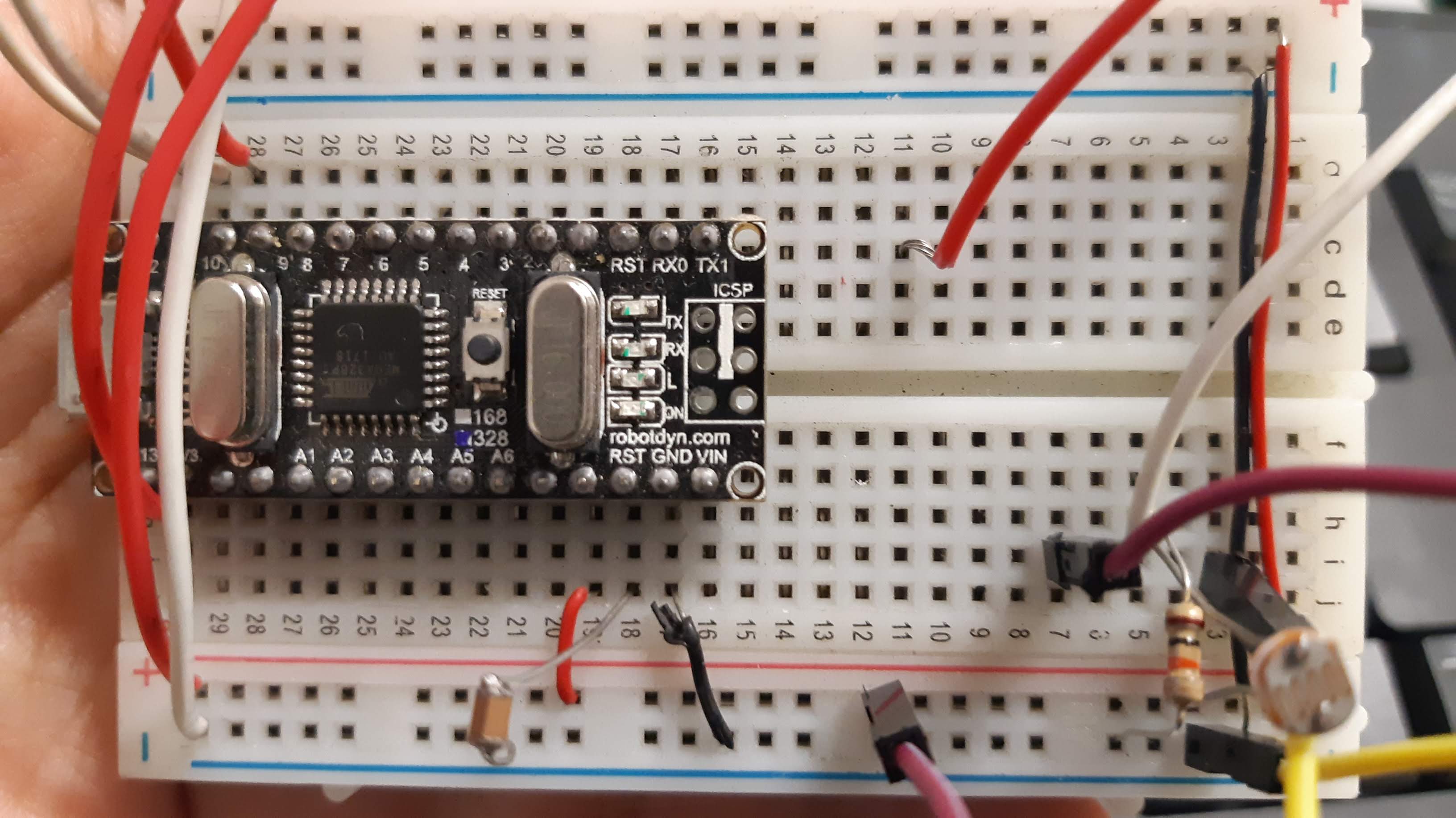
Now for the connections
In the list above, there's an extra 10µF that we need to connect to the Ground and Reset pins on the Arduino. This capacitor will stop the Arduino from resetting itself when programming ATtiny
Now we will be using the ISP header from our board and make the connection to the Arduino in the following way.
SCK to Pin13
MISO to Pin12
MOSI to Pin11
RESET to Pin10
VCC to 5V
GND to Arduino GND
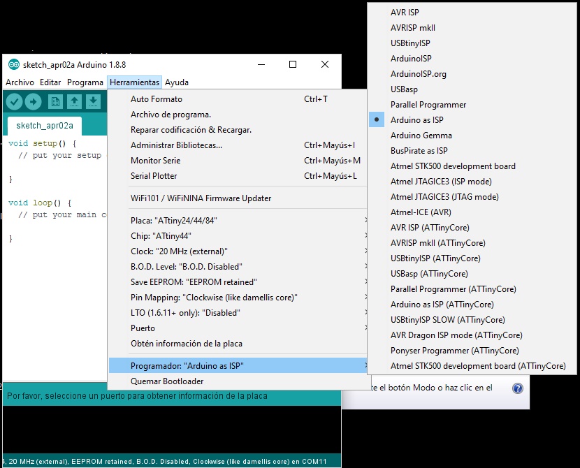
Now we need to select the correct board, processor, clock and port.
For the programmer we choose Arduino as ISP
If needed run the "Burn Bootloader" option.
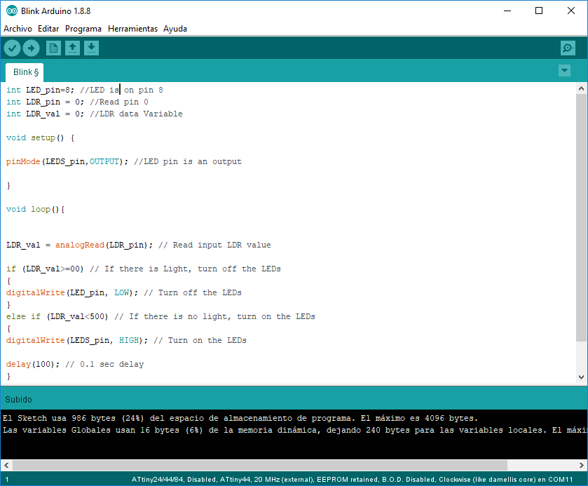
Upload code
We can start trying to upload a simple code to see if it is working. I tried with a simple blink.
Once it's working we can start
MICROCONTROLLER
Attiny 45
Now that I know how this works I am designing a new PCB, this time using a different micro-controller, the Attiny 45, you can check this microcontroller's datasheet HERE
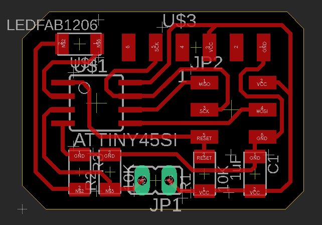
DESIGNING THE PCB
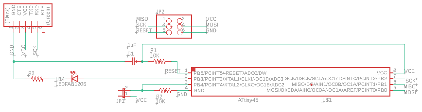
SCHEMATIC
After checking how the attiny 45 works I was able to select the electronics to be used and connect the LDR to the micro-controller.
list
Attiny 45 microcontroller
10k Resistor (2)
1uF Capacitor
ISP pin header (2x3)
FTDI pin header
LED smd
499 ohm resistor
LDR
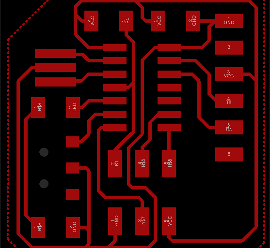
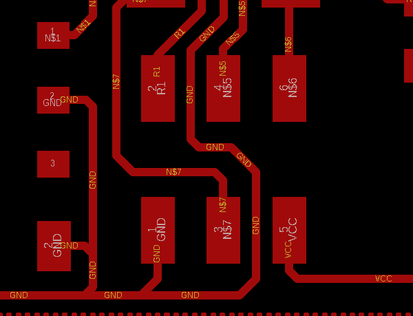
BOARD
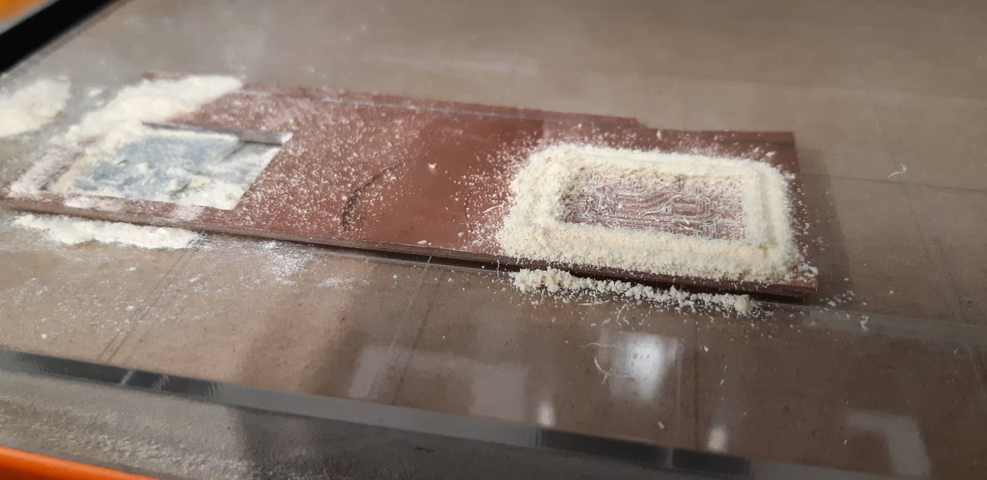
MILLING THE PCB
FLATCAM
In this opportunity, as I needed to make some drills for the LDR I decided to try FLATCAM.
In the beginning was a little hard but once you understand how it works, I think it makes the drilling part very easy.
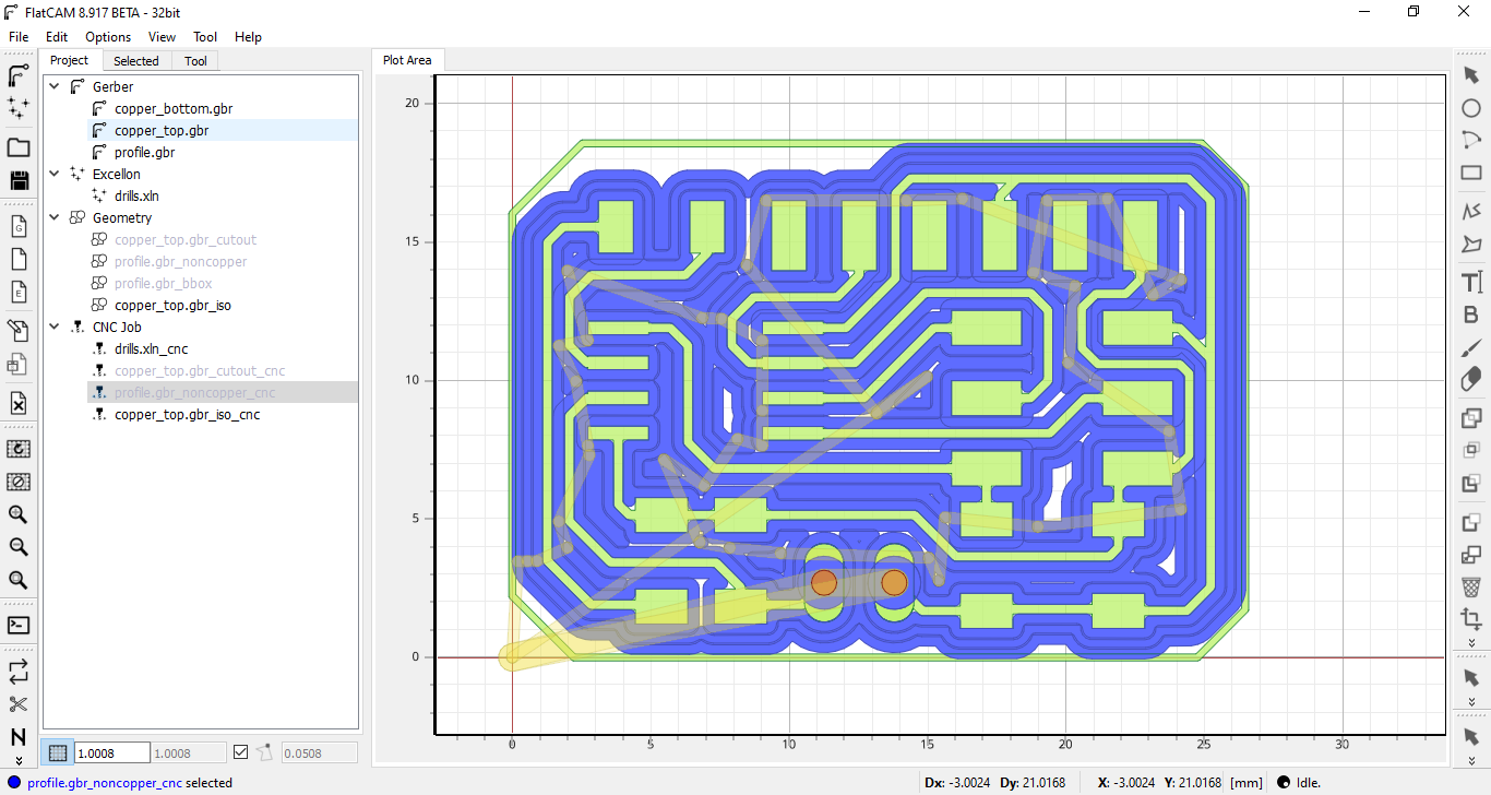
It generates different gcodes for every process. In this case I generated 3 files, one for the pads, another one for the drills, and finally one for the outline
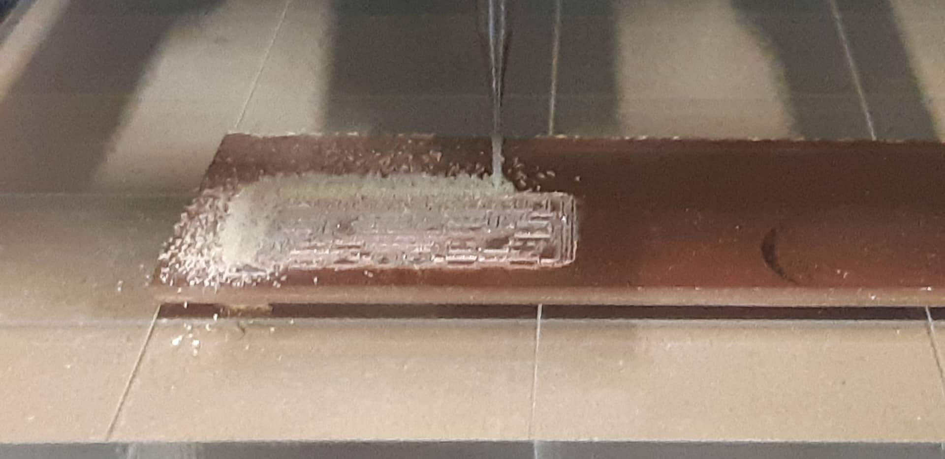
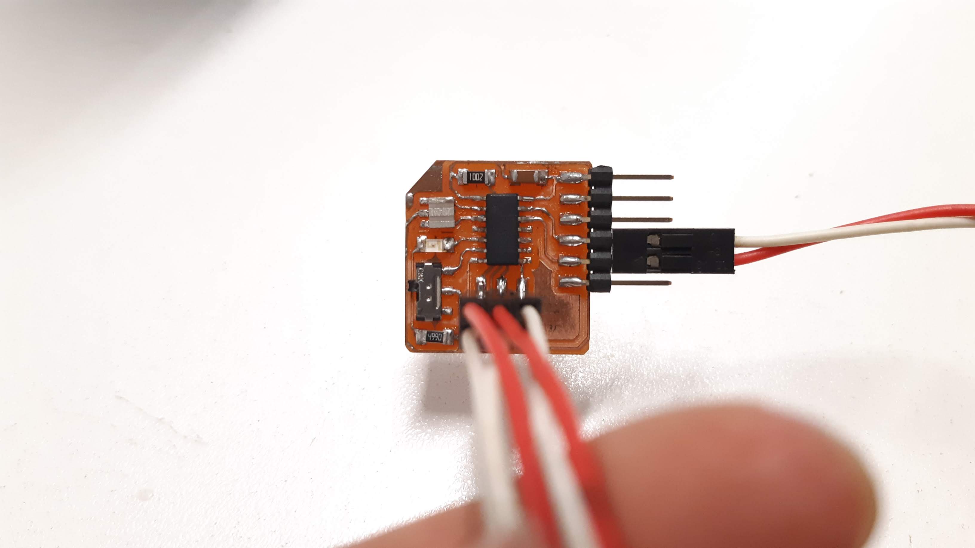
I actually made two of them.
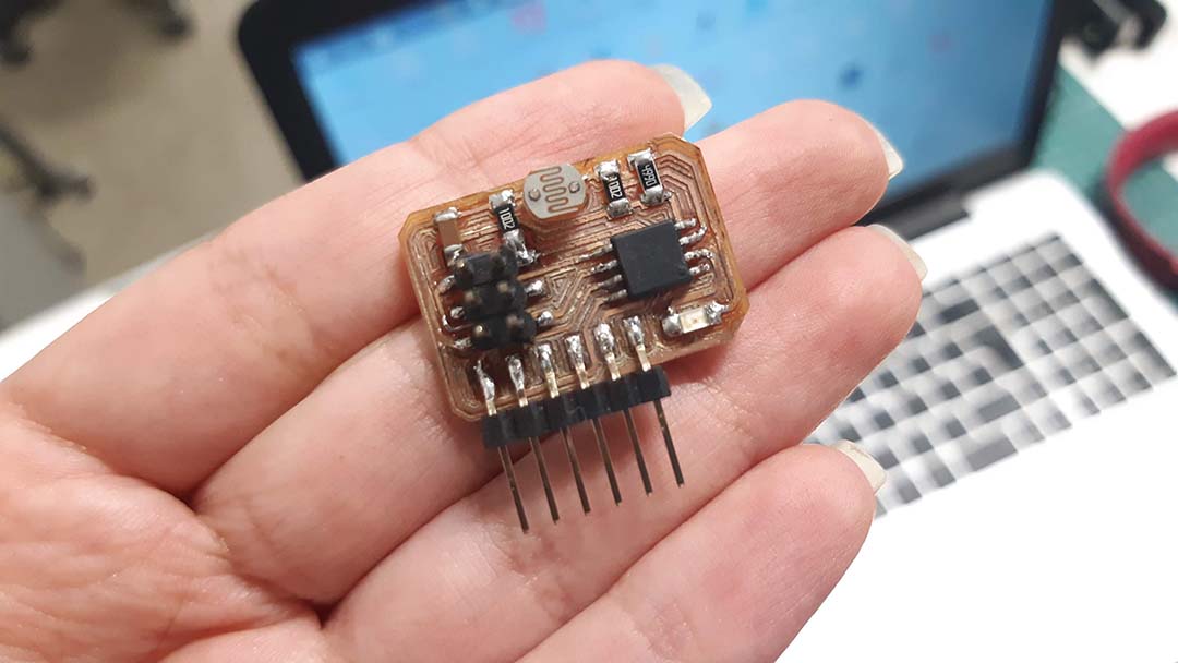
Here you can see the board with everything soldered.
BOARD PROGRAMMING
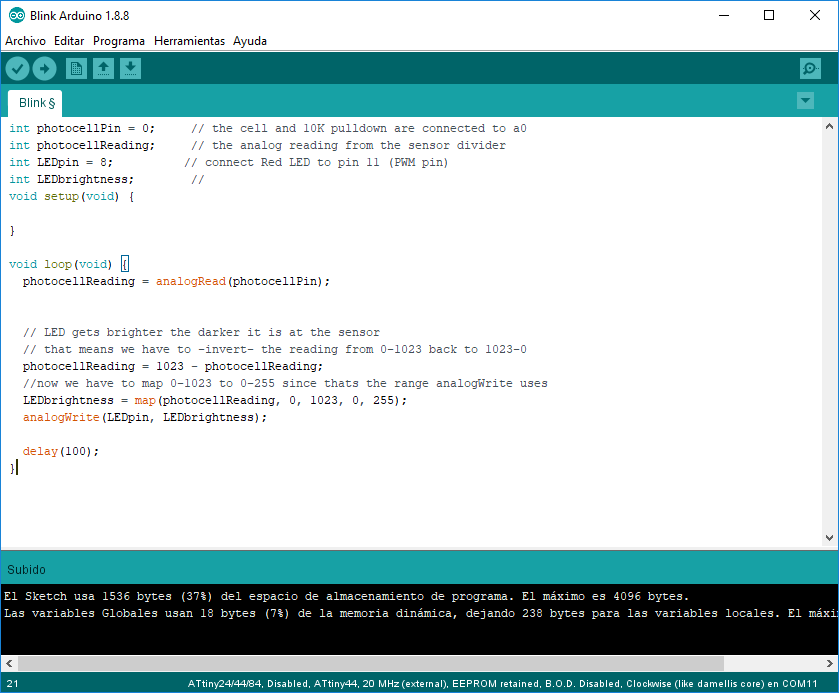
ARDUINO
I used arduino to program my board.
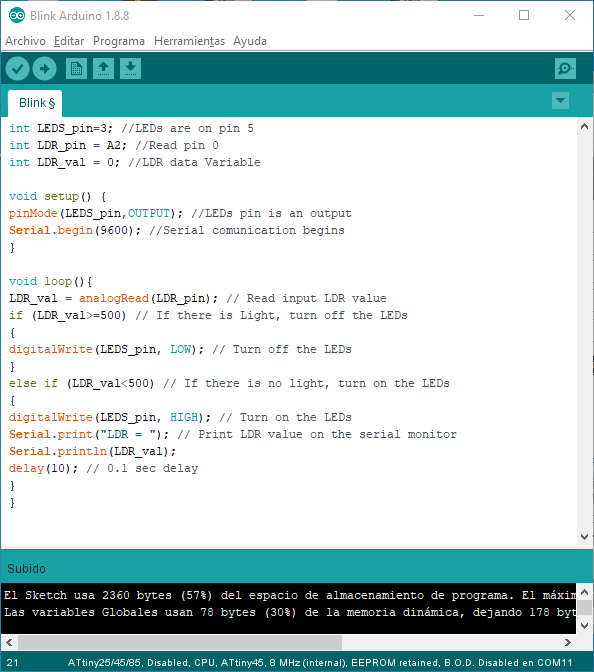
Here you can copy the code I used.