Twelfth assignment
03 April 2019
Week's assignment
This weeks assignment was to add an output device to a microcontroller board you've designed and program it to do something.
I decided to use the same board from the previous week's assignment and program the input device I used then, to work with an output for this week.
Attiny44
pinout
To program the ATtiny 44 there are 6 of the 14 pins that are used.
The six pins we use for the programming are:
MISO (Master In - Slave Out)
MOSI (Master Out - Slave In)
SCK (Serial ClocK
VCC
GND
RESET
Programming with Arduino
Output
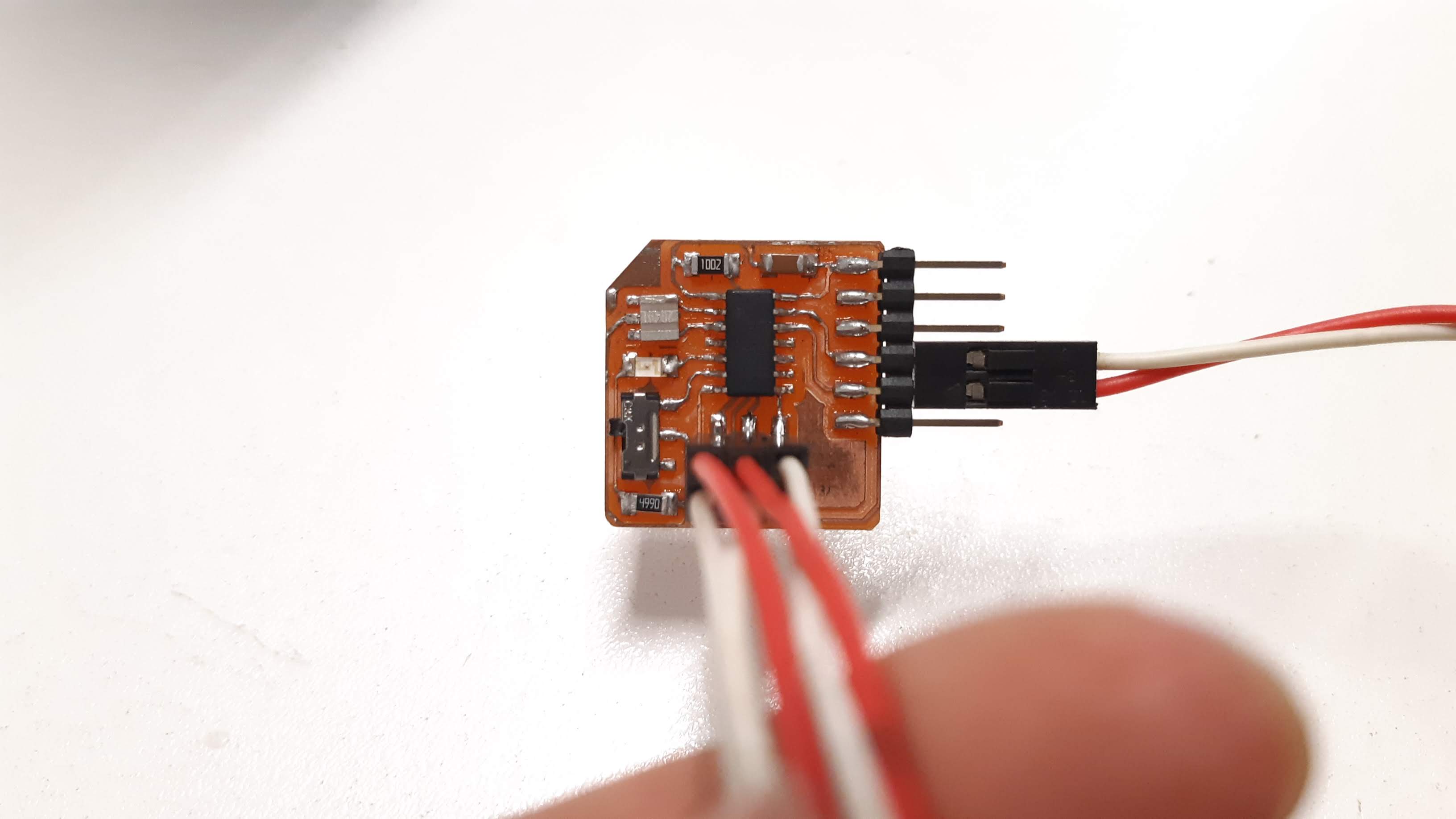
I programmed my board with an arduino nano, you can check the process and the right connections to do so in my week 11 page, for the Input devices assignment.
Uploading the code
Of course you need to be sure first to have all the connections needed, ready.
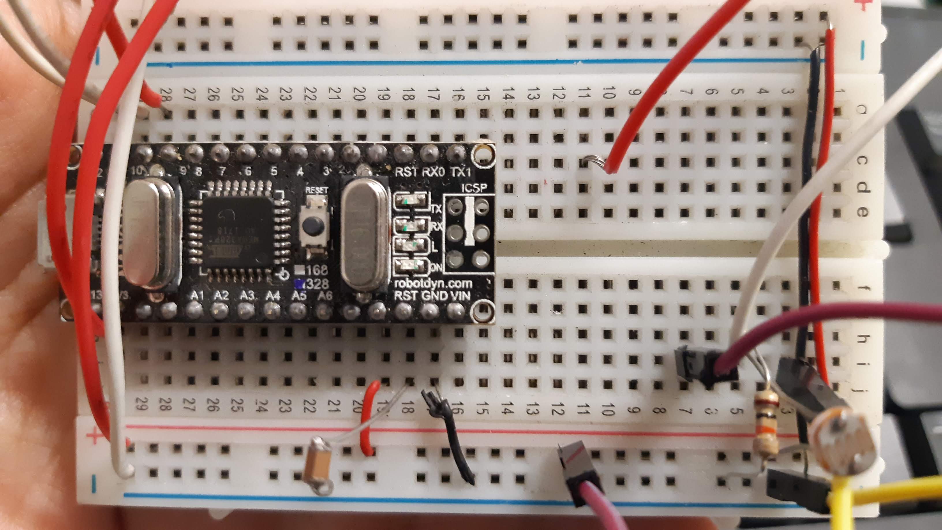
It wasn't hard to program my board as I did the same process one week before. This is the code I used.

And this is the final result.
OUTPUT
Led array
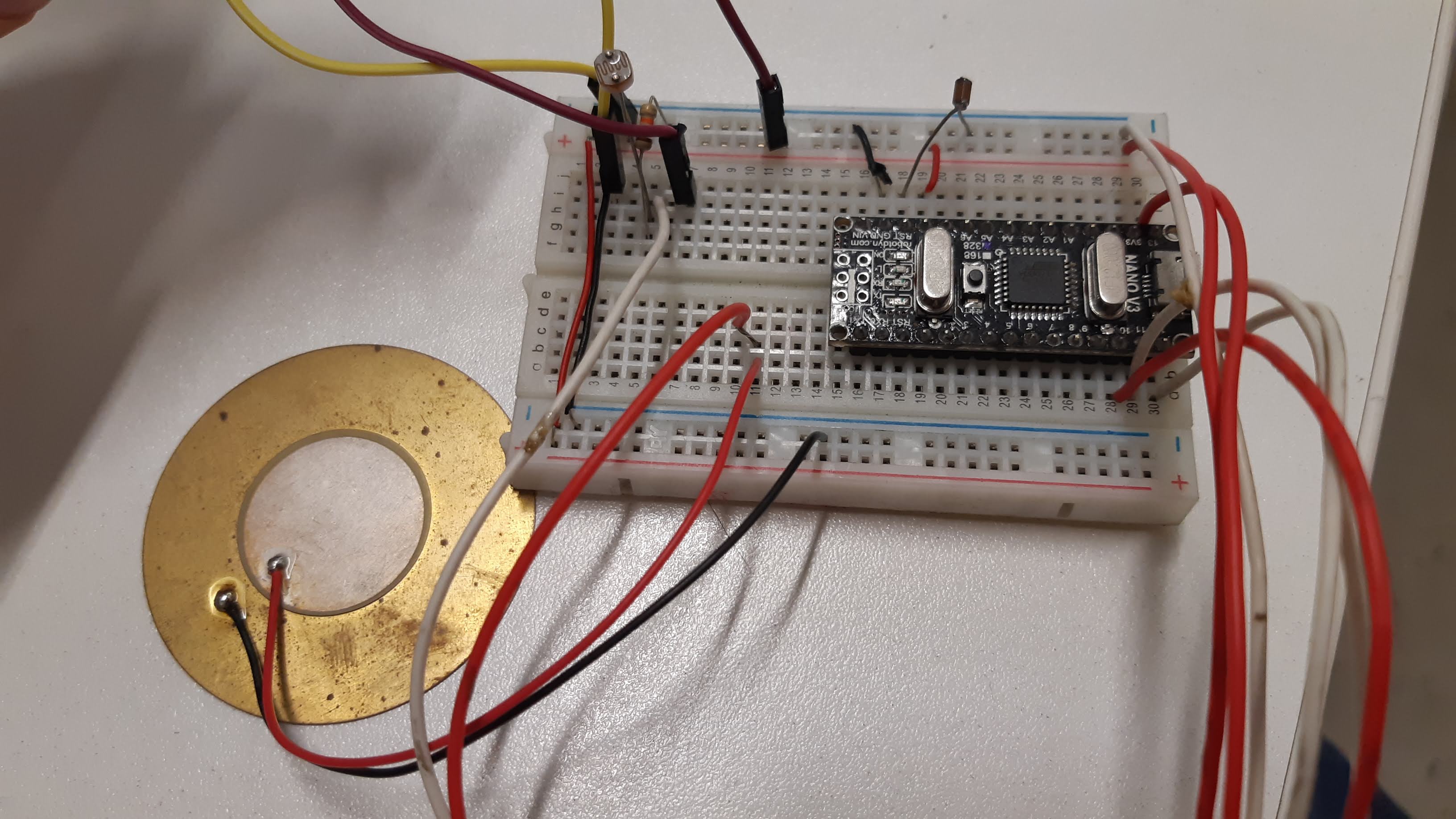
I used part of the assignment's deliverables for the final project. The interface is one of the most important parts I need to focus on, in this case, light is the one I started making tests with.
Another very important aspect of my device is that it should be powered by a small size battery, I am planning on using a 3v button battery.
As I am planning on using a significant amount of smd leds (considering the size of the design). It was hard to choose between a serial and a parallel connection, but after some investigation and testing some leds with a protoboard and an arduino, I decided to go with a parallel one.
Next step was figuring out how to choose the correct value of the resistors. Fortunately I found very helpful information in this page.
Basically, what I did here is a simple calculation and I decided to go with a 1 Ohm resistor.

Making the board
Schamtic
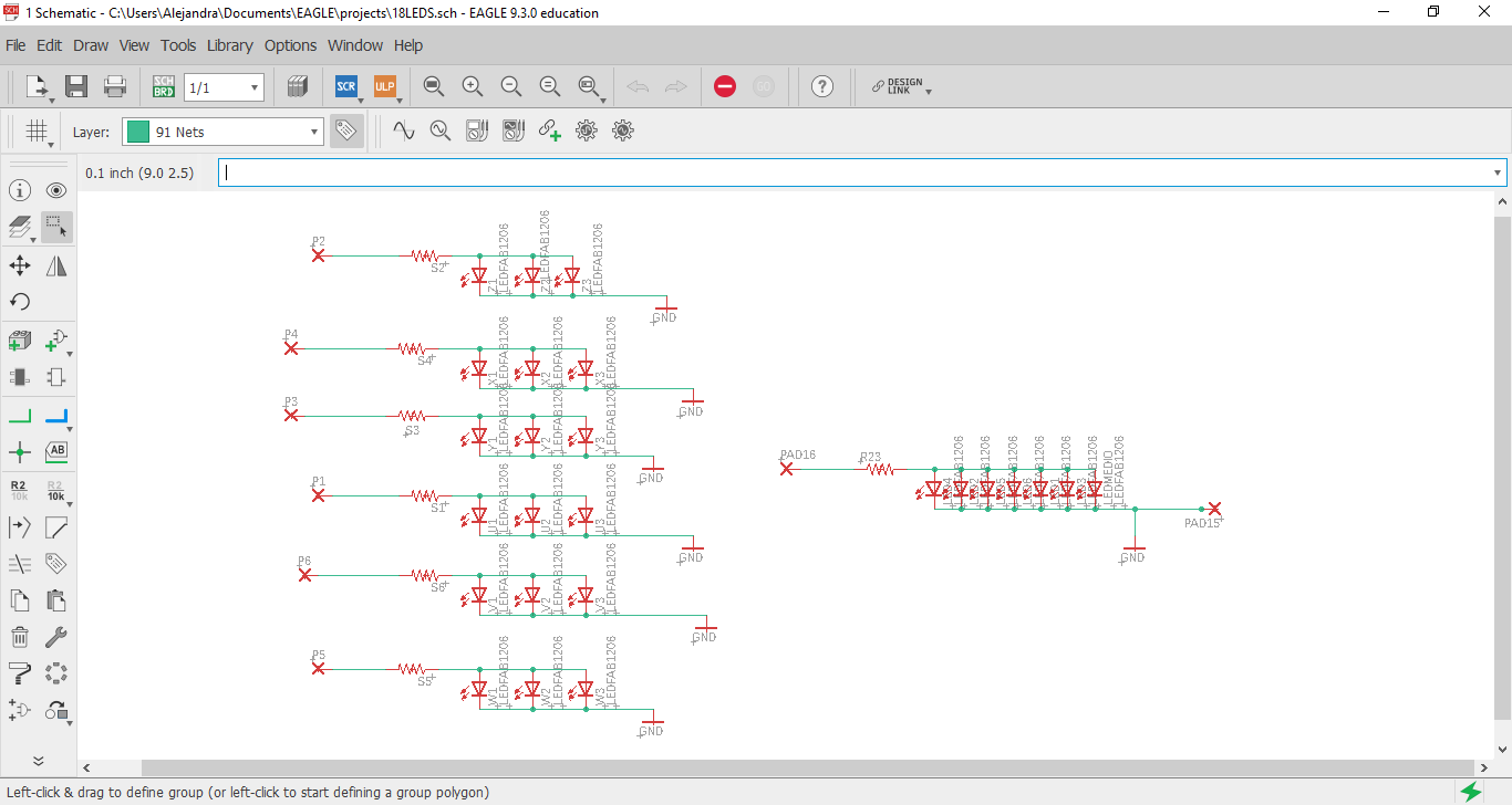
First of all we need to make the schematic archive in Eagle.
As you can see below, I only have the LEDs and the resistors connected here, that is because given the size of my project I didn't have any more room to add a micro-controller on the same board (or at least on the same side of it).
Board
Secondly, it was time to arrange the leds in place.
This actually took me some time, as I hadn't done anything like this before, but steps are quite simple.
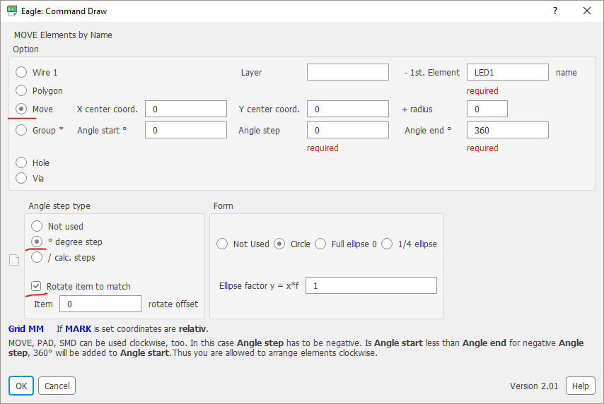
Go to file>run ULP>cmd-draw.

You need to select the move option and then add the name of the first component you want to move. In this case I started with LED1, this command will move each component in order of the count so depending of the components you want to move you should assign the same name with the respective number depending of what order you want them to be in.
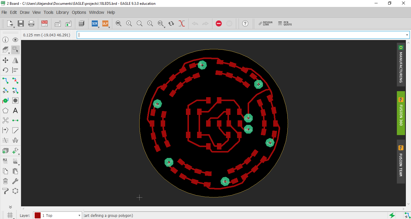
For me I used the Rotate item to match option for the bigger circle but did not for the inner one.
This is how my finished board.
Test
Finally I connected my board to a voltage source and test it. It came out great!
IC design
ATMEGA328P
The Atmega 328p micro-controller is a high performance, low power AVR® 8-bit microcontroller. I chose to use this one because of its capacity and the number of output pins I was going to use, also this is probably the one I am going to be using for my final project for which I am adding some other features.
First of all, I had to read the Datasheet, and understand which pins would be right for this assignment.

In order to make this board working I will make two important connections:
Connect a 10k Resistor to the reset pin
Connect a 0.1uF Capacitor to Aref

After that I connected the pins: A0, A1, A2, A3, A4, A5, B5. This will work for the LED output.
I also put some paths that I think might work to connect some other ouputs and inputs that are going to be useful for my final project.
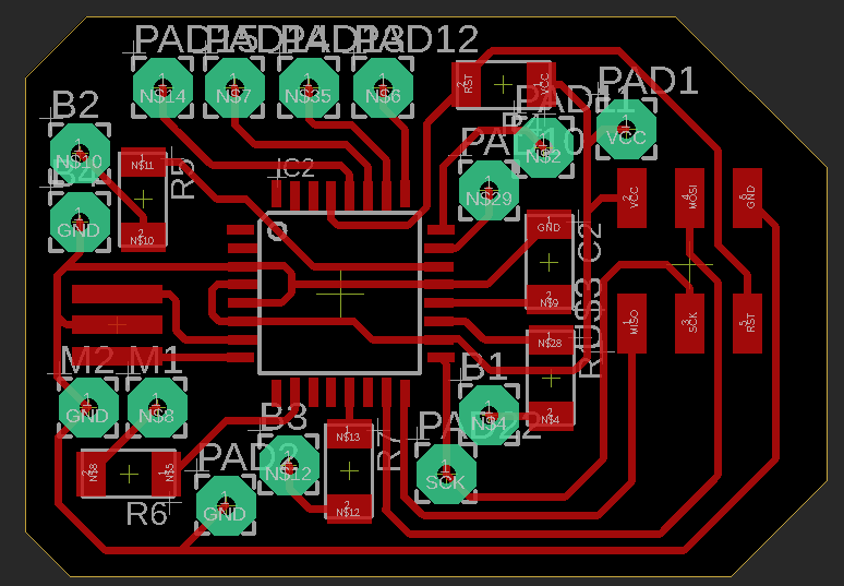
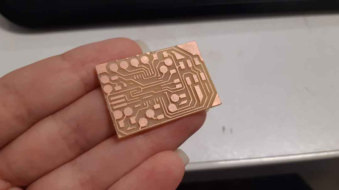
This is the board I milled.
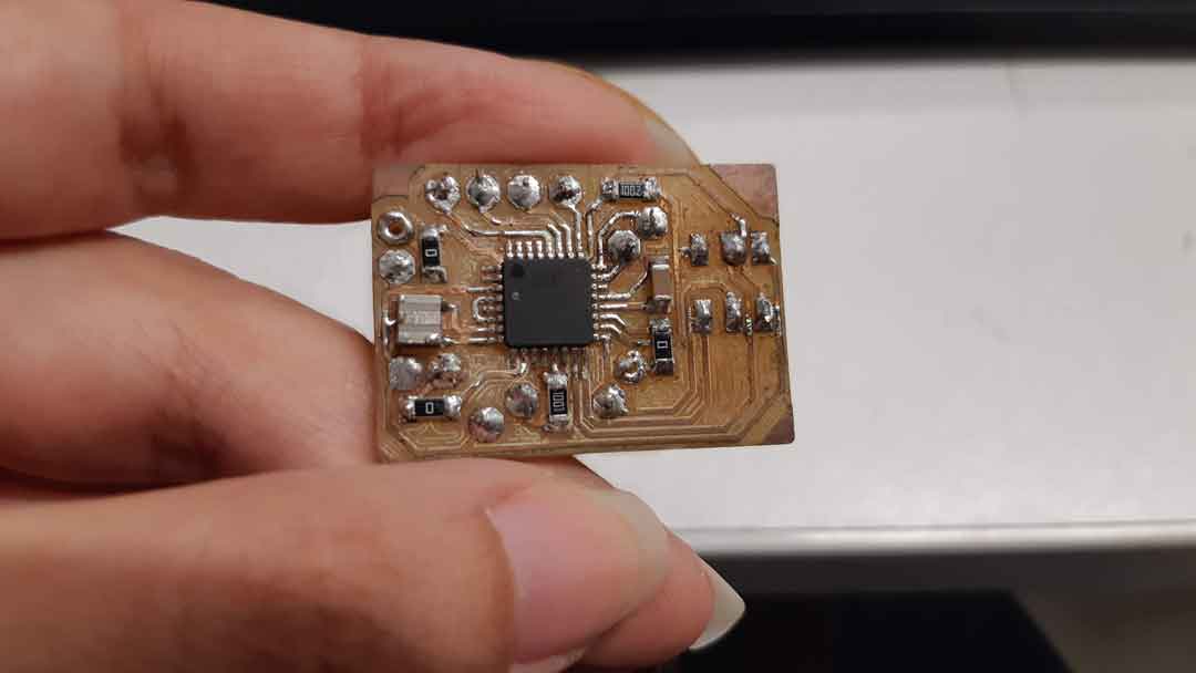
PROGRAMMING
I programmed my board with arduino. Code is pretty simple, I just defined the outputs and make a sequence blink for all of the output pins.
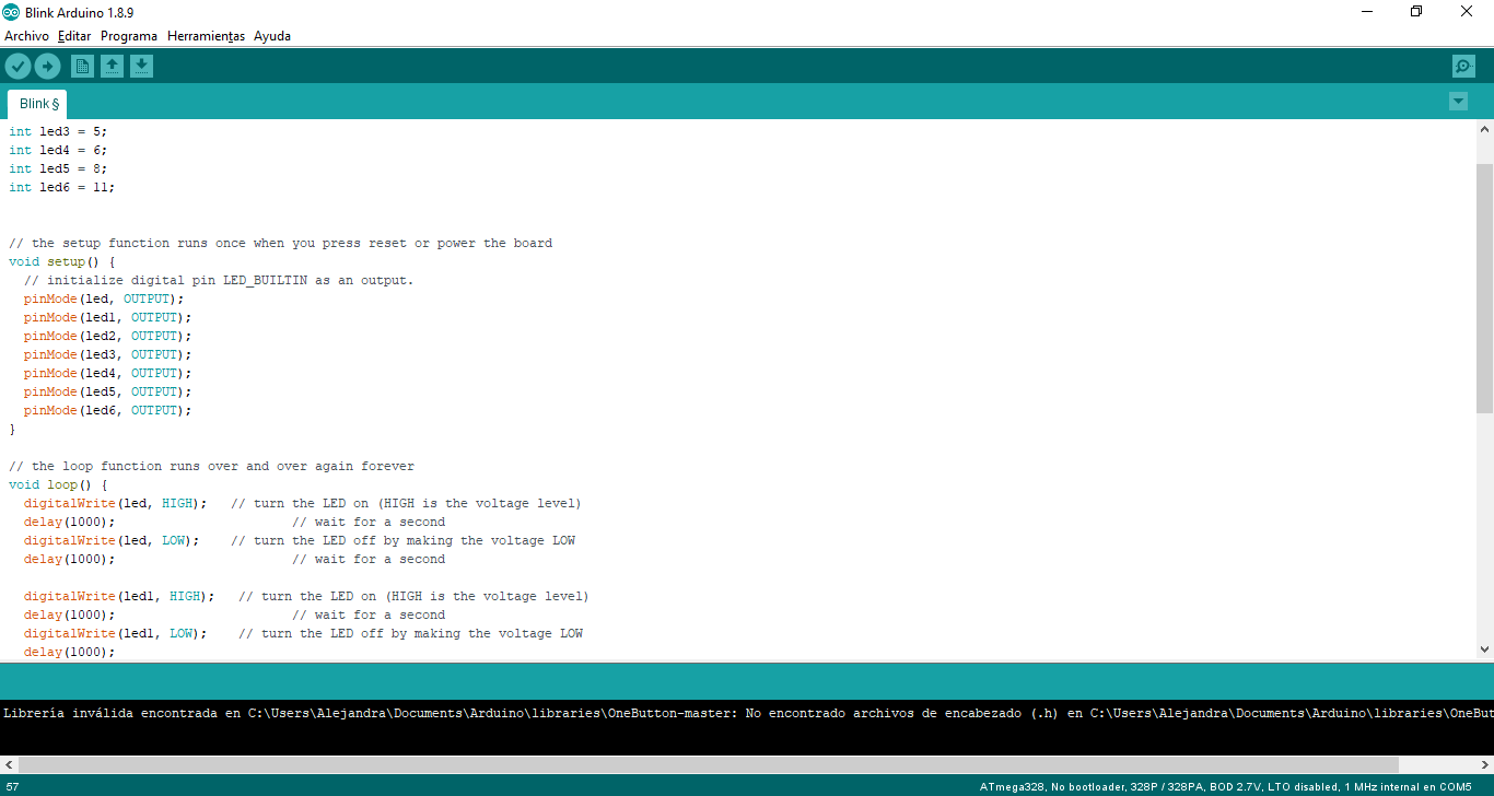
Here you can copy the code.
board working
You can see here the board working with a power source of 3V.