Fifth assignment
6 February 2019
Part I
Characterize specifications for the PCB production process
Part II
Make an in-circuit programmer
Part I
There are two parts for this week's assignment.
First part is the group assignment: characterize the design rules for your PCB production process.
Second part is making an in-circuit programmer by milling the PCB and program it.
I will be showing first part below and second part in the next page.
PCB production process
Milling machine
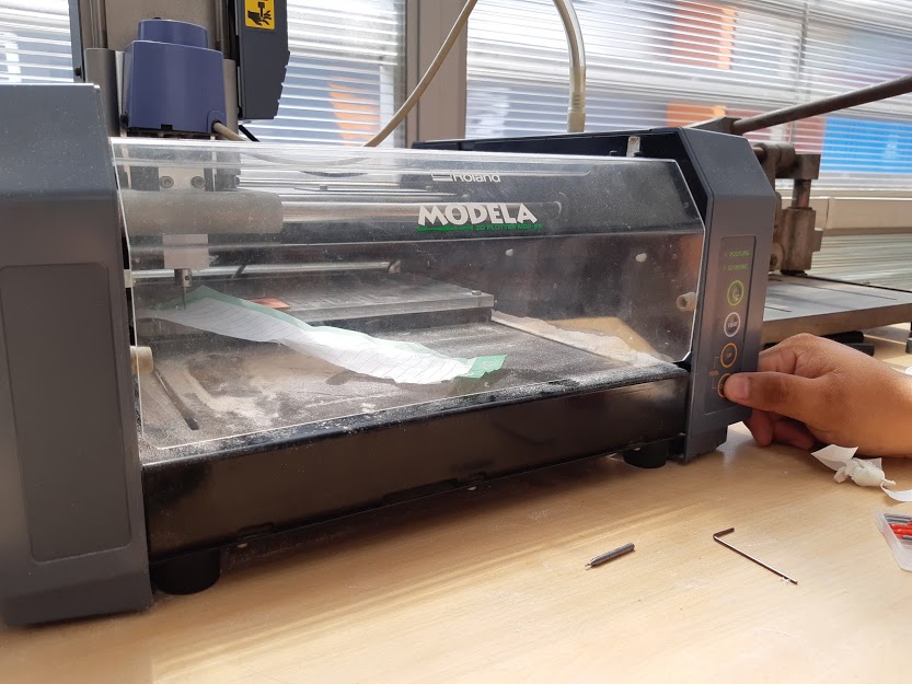
We have a Modela MDX-20 3D Milling Machine at Tecsup and I learned how to use it while some of my classmates were doing the group assignment.
Then I used a Roland SRM-20. It is interesting to see two different machines, although they are similar and from the same brand, there some details that may be important for some people to choose one over the other.
Milling process
Setting parameters
There are some things we need to take into account
The end mill
The zero position
The speed (and other parameters)
The end mill
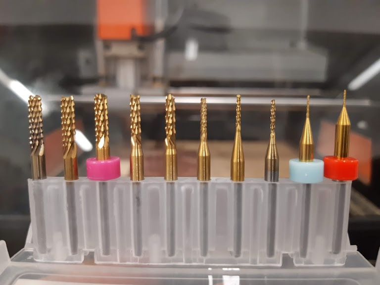
There are cutting tools that specific for machining PCB. For the traces it is recommended to use the 1/64 end mill and for the outline the 1/32.
As you can see in this picture there are different sizes. The diameter of the tip will determine how much material will be removed in each pass.
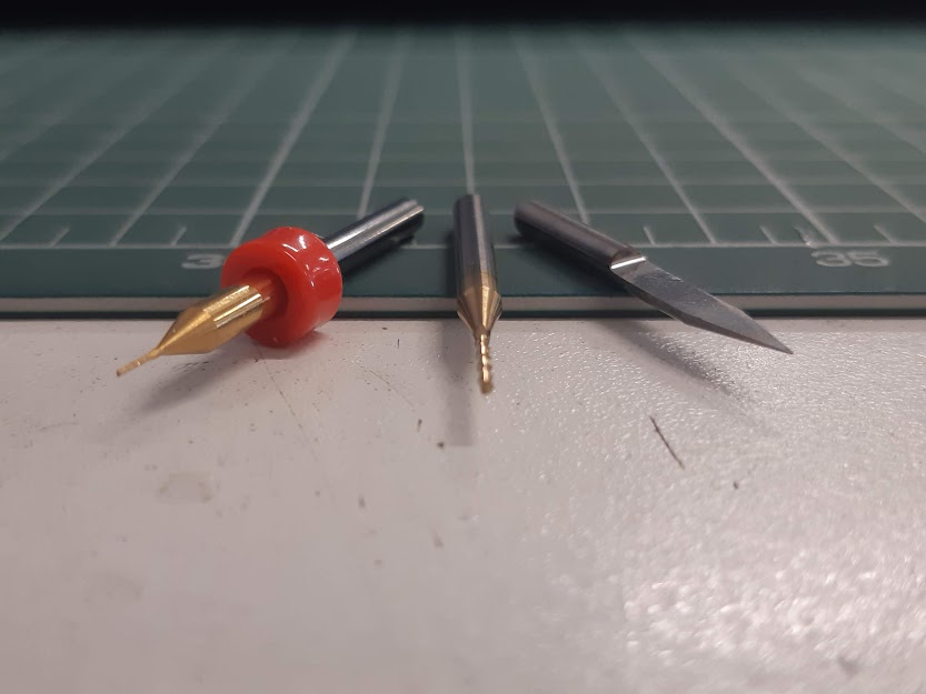
In the next image, from left to right, we have the 1/64 and the 1/32 end mills. The last one is another type we tried, the V-mill for PCB that can also be used for other materials such as acrylic, nylon, pvc, etc.
These are the tools we chose to make the tests with.
The zero position
This is very important for the process if the 0 position is set wrong, the cutting part will be messed up.
This part was interesting for me and also made the difference when choosing a machine which I felt more comfortable with.
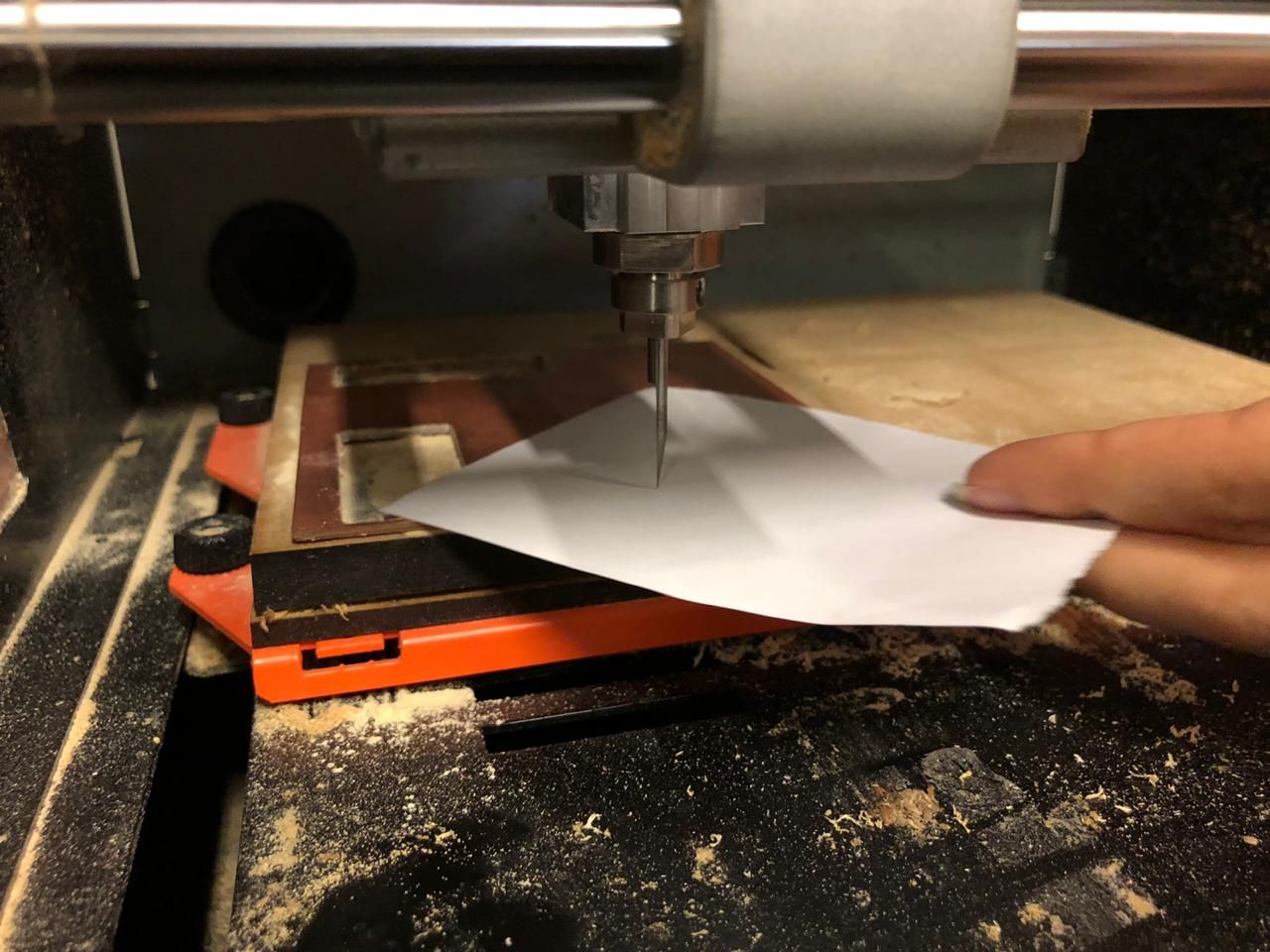
For the Modela the calibration for the x,y axis were made from the mods page, working from ubuntu, but for the z (as we need to actually see and check that the tool is touching the material) we did that manually pressing a button as you can see in the next image. Each time you press the button the spindle turns on and start descending. We used a paper to know the exact moment the cutting tool had a contact with the paper.
With the SRM-20 we worked with windows, and with Fab Modules. What we did here was setting all the parameters and save the file. Then open it with the machine software, calibrate and cut.
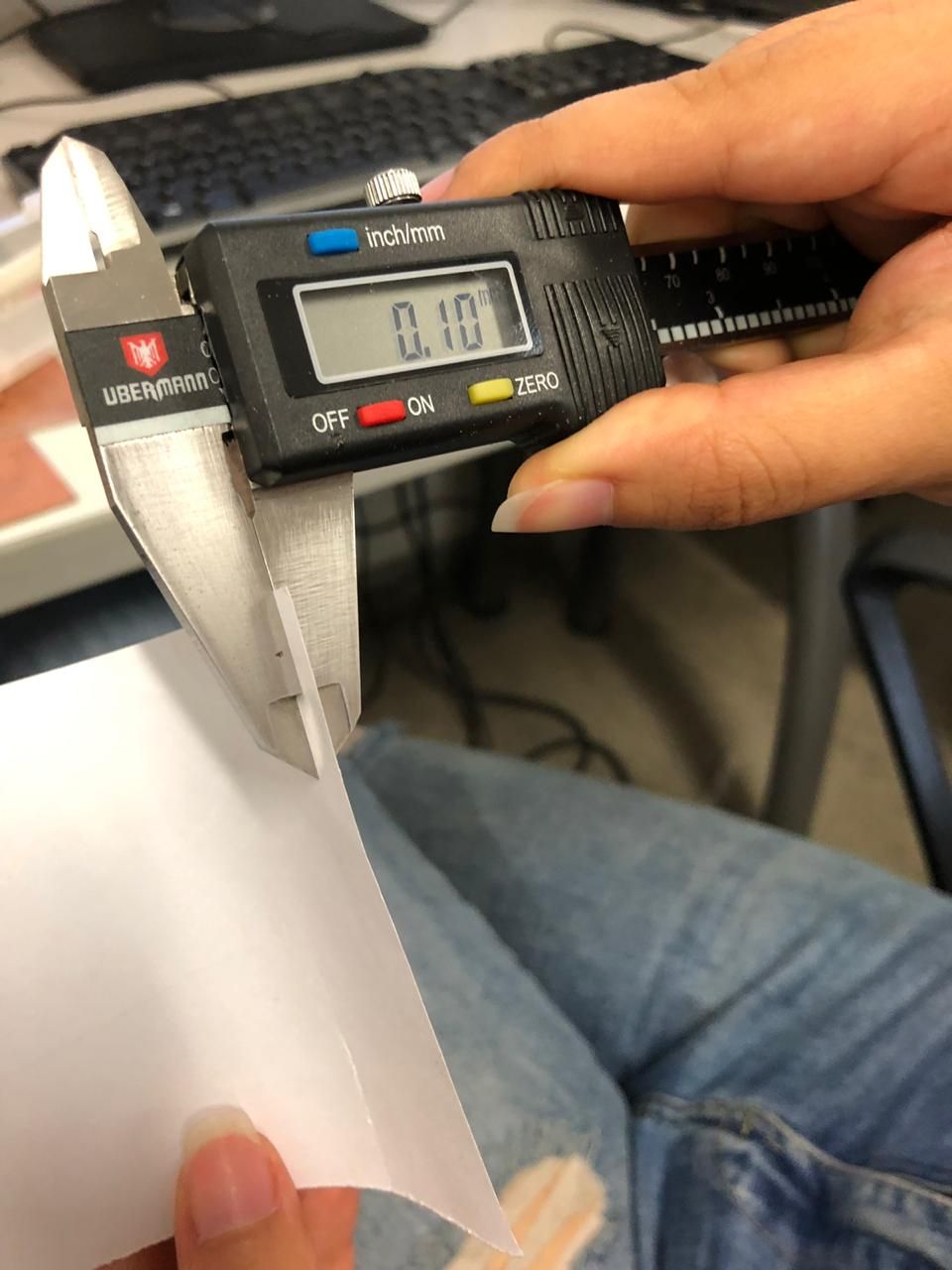
You can control the movements from the software and you can be as precise as 0.001 mm each step. We moved the x and y axis and then set it as the new 0. For the z we also used a paper moving it till it was slightly pressured by the end mill then we moved the z axis 0.1 mm down (which was exactly the paper thickness).
The speed (and other parameters)
For the cutting process there are some parameters we need to control to have a successful cut.
Regardless of the interface, what we have to check are the following values:
Tool diameter
Cut depth
Max depth
Offset number
Speed (mm/s)
There are default settings for mill traces and mill outline. If it is the first time your doing this, like me, you should probably use them and then start trying new values. This helped me understanding perfectly how to change the parameters strategically, according to what I wanted and needed. Also if you are using a new end mill bit you may want to reduce the speed maybe to 3 mm/s to reduce the chances of a broken tip.
Using mods may seem a little confusing at first but it is actually easy to understand
You can always check the Fab academy tutorials/mods to understand how to use it.
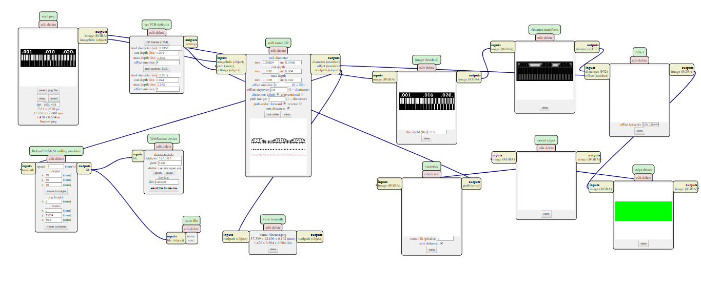
Fab Modules looks more organized for me, although I could work with both of them.
You can also check PCBs with SRM-20 as part of the Fab academy tutorials to understand how to use it.
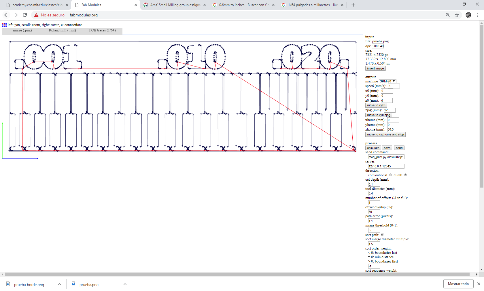
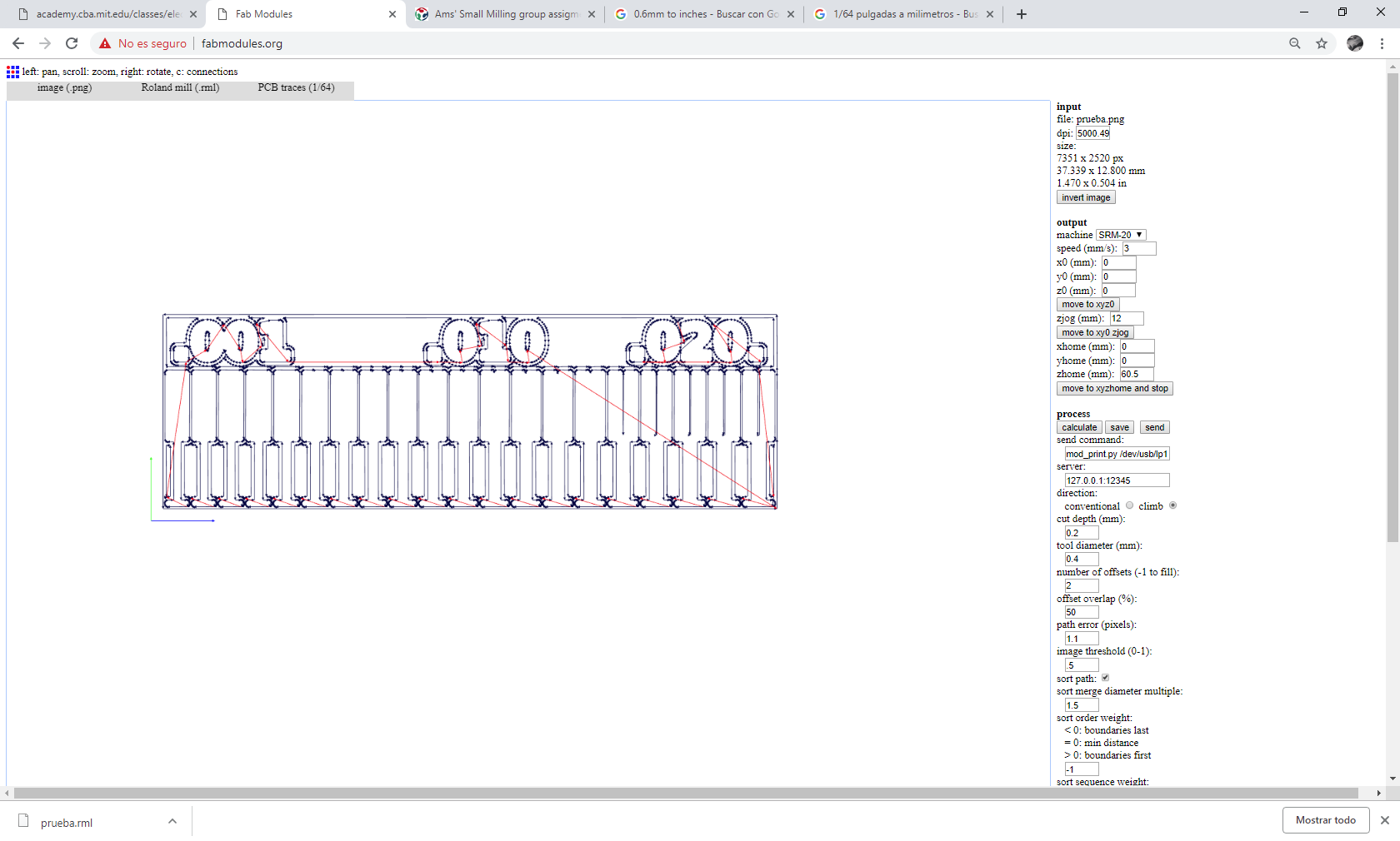
We load the linetest.png file
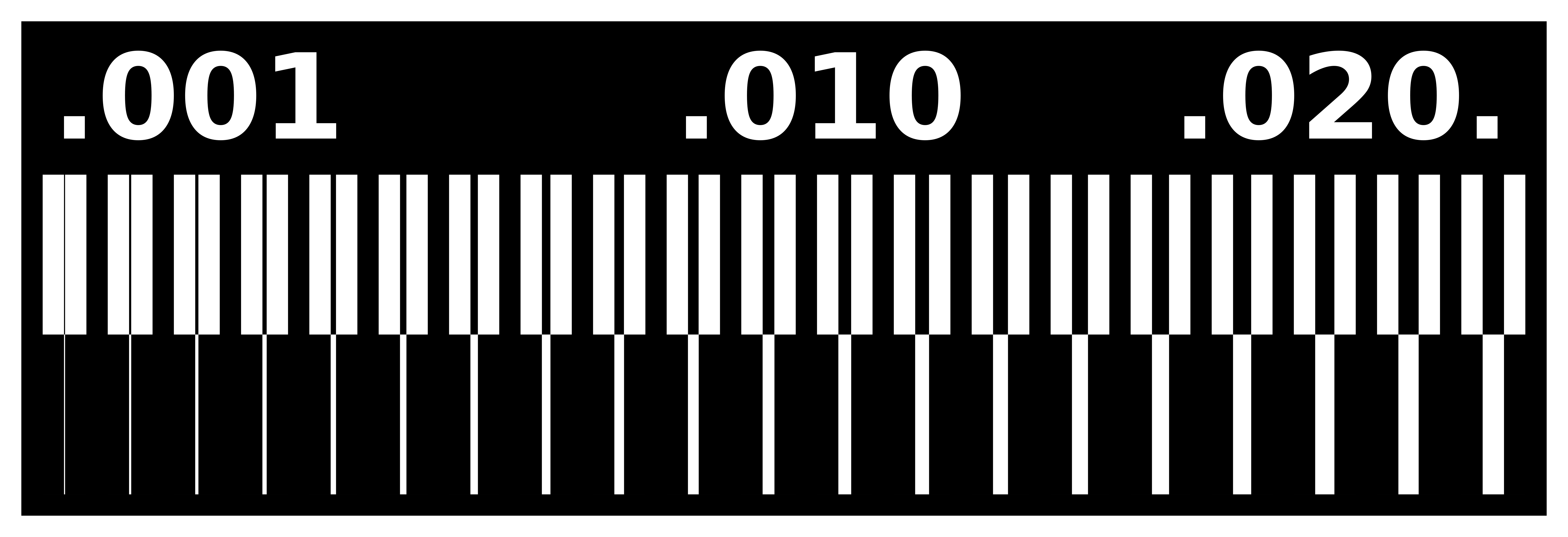
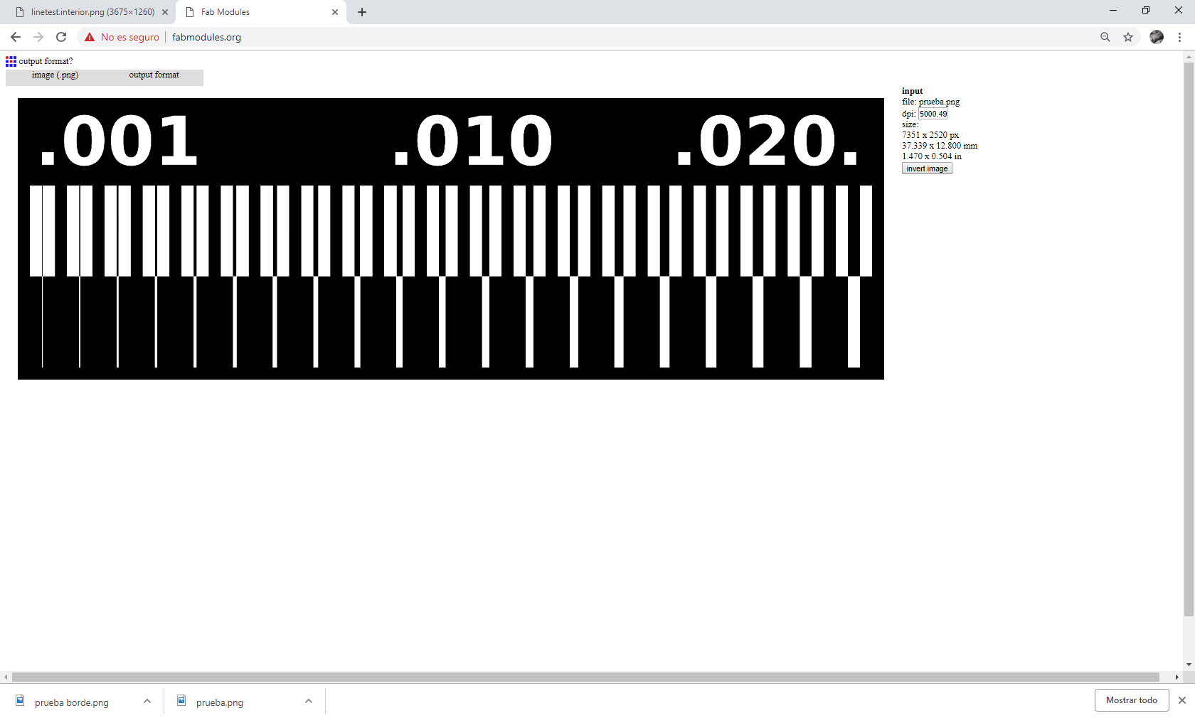
As you can see here we generated two files for the tests. One with 0.1 mm for the cut depth and 1 offset, and the second one with 0.2 mmcut depth and 2 offset.
Milling process
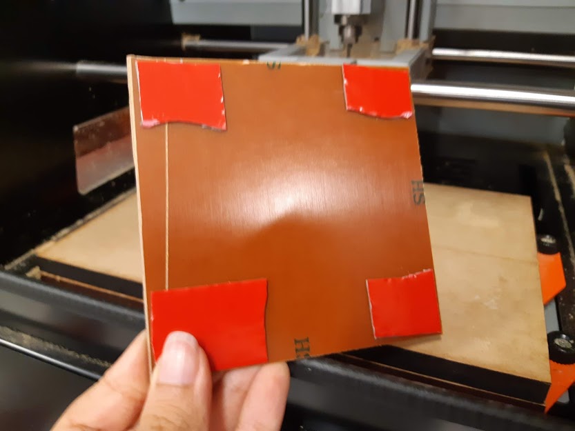
First thing we needed to do is secure the PCB to the cutting platform. We used double sided tape.
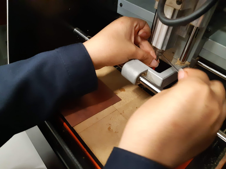
Then we adjusted the end mill we started with the V mill.
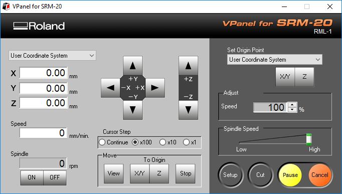
Once we have the cutting tool and the material ready, next step is open the Software for the SRM-20.
Now we can set the origin point. We can see the spindle and the end mill moving as we click on the arrows. We need to be very careful when moving the z axis controlling the cursor step, otherwise we can damage the end mill.
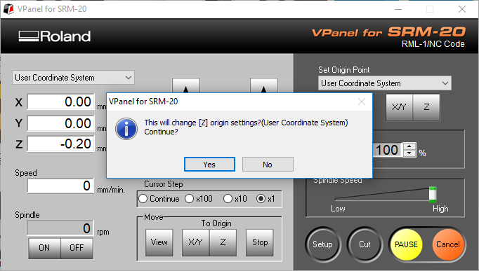
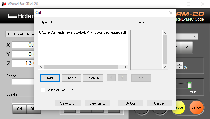
By clicking in the 'cut' button a windows is opened where you can add your files. Select the file you want to send at the moment and select 'output'. It will instantly start running.
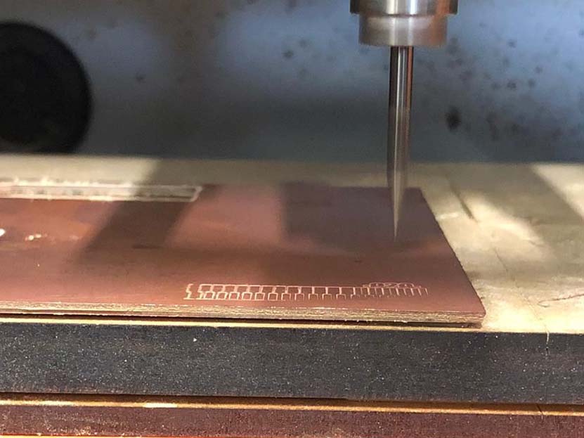
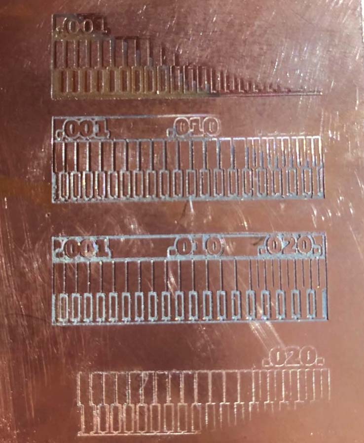
We started with 1 offset and 0.1 mm cut depth.
As you can see, it wasn't exactly a success, I think that if you want to use a really low cut depth you need to have all measured extremely precisely. On the other hand the tip of the cutter is so fine that it will probably need to go deeper in order to take out enough material to consider it a pass or a trace. So we tried the next file.
Here the result with 2 offset and 0.2 mm depth.
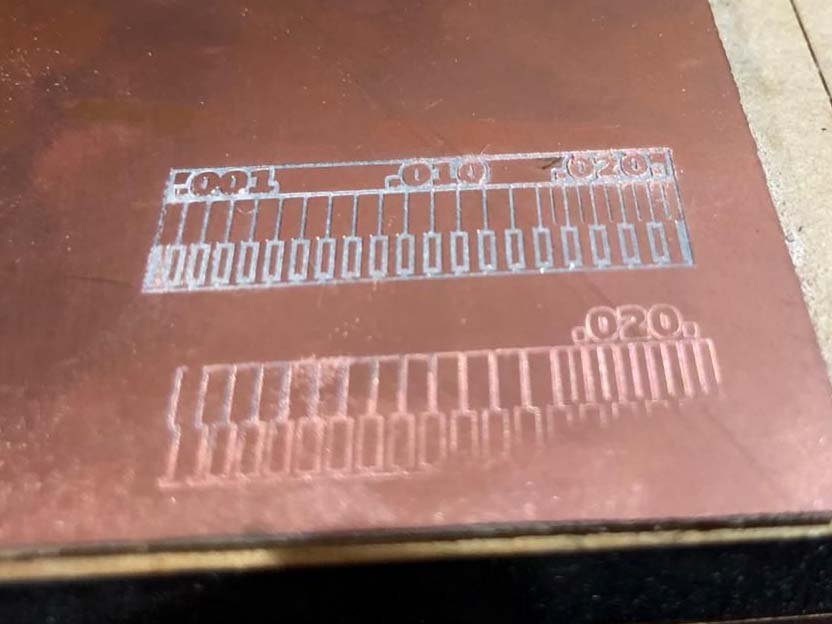
We repeated the process with the 1/64 end mill. But at first we had trouble finding he correct origin point for Z. At the end we measured the thickness for the paper, so we repeated the process by moving the paper while moving the z axis and then move the tool down by 0.1 mm and problem solved.
These are the results for both archives. It wasn't a success either but this time the reason was that the platform was damaged right where the PCB was supposed to attached and supported, generating a little drop for the top right corner.
We concluded that for the v mill we needed to go a little further in depth for the actual form of the end mill. After this we felt ready to make our own electronic board.
Part I
Characterize specification for the PCB production process
Part II
Make an in-circuit programmer