Ninth assignment
13 March 2019
Embedded programming
There are two parts for this week's assignment.
Individual assignment: Read a microcontroller data sheet. Program your board to do something, with as many different programming languages and programming environments as possible.
Group assignment: compare the performance and development workflows for other architectures.
Reading datasheet
Attiny 44
The micro-controller I'm using in my board is the Attiny 44. When I was designing my board with the components I had I check the Attiny 44 data-sheet to know how to connect the switch and what I needed for it to work properly.
I had a quartz crystal so I had to check how it was possible to use it.
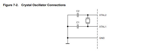
You can check this on page 26
Also it helped me when designing the board and program it with the switch and no external resistor. You can check Pin Descriptions, In this case ports A and B have internal pull-up resistors.
Programming
arduino
This is an open source electronics platform to program with code.
Settings
To program our board with arduino, we need to add support for attiny to arduino, it is very simple to do so.
We just need to add an url address, by opening the preferences dialog and pasting it where it says Additional Boards Manager URLs. You can find different ones on the Internet, but in this case I used http://drazzy.com/package_drazzy.com_index.json
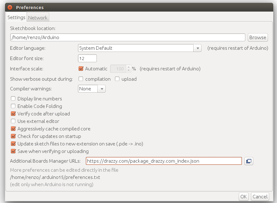
Then I opened the boards manager and searched attiny, selected it and installed it.

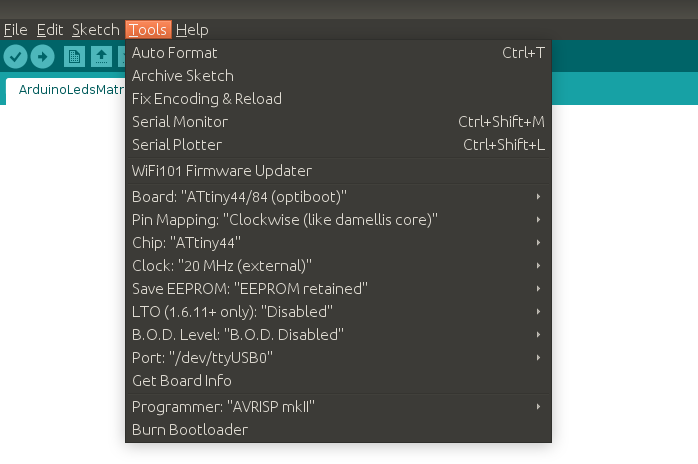
Now we can choose different settings and values.
In this case I just had to modify or pay attention to these:
board
chip
clock
pin mapping
port
programmer
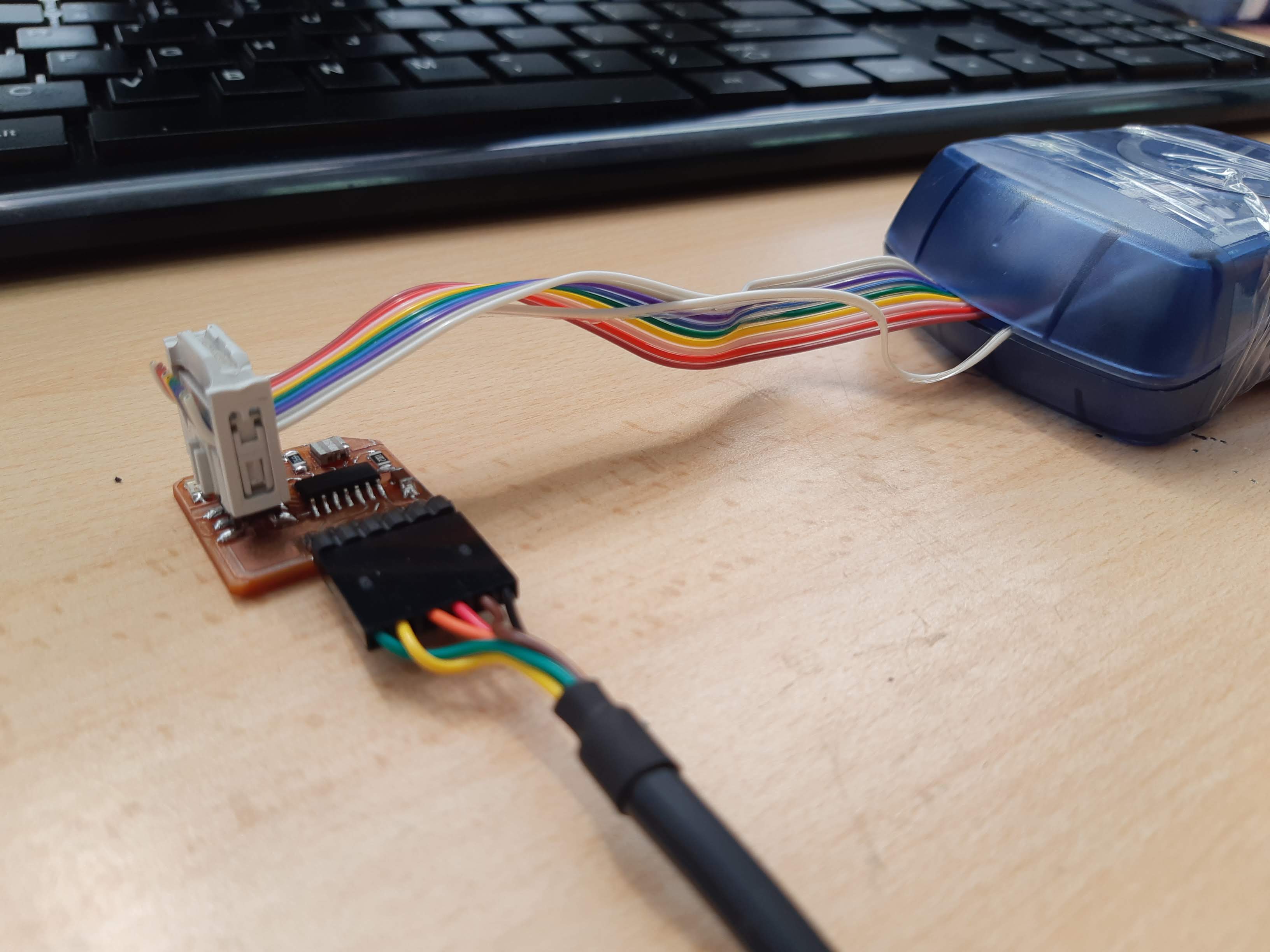
Here's how I connected my board. this time not only the ISP connector position is important, but the FTDI as well.
If you have the connector already and you didn't messed up switching the pins in the schematic part you can just make sure you connect the ground wire/pin correctly.
the CODE
Blink
To get started and check that all the settings are okay and that our board is working correctly we can start with a blink. We can find and example code going to file/examples/01.basics/Blink.
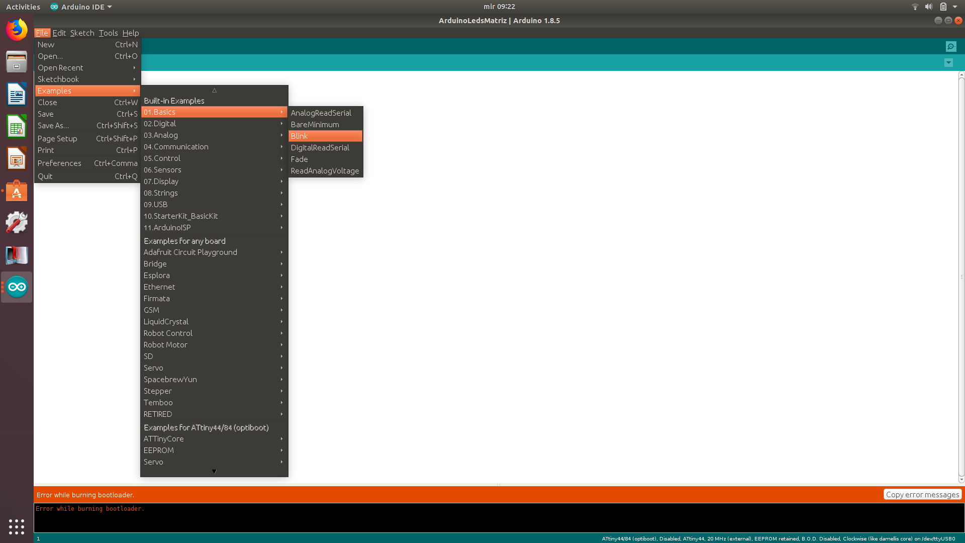
It should open a new window with the example
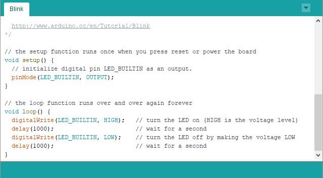
Before writing the code or in this case, modifying it we need to check which pins we are using. As it is not the same for the arduino language we can check this pin out diagram.
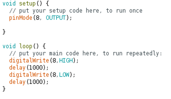
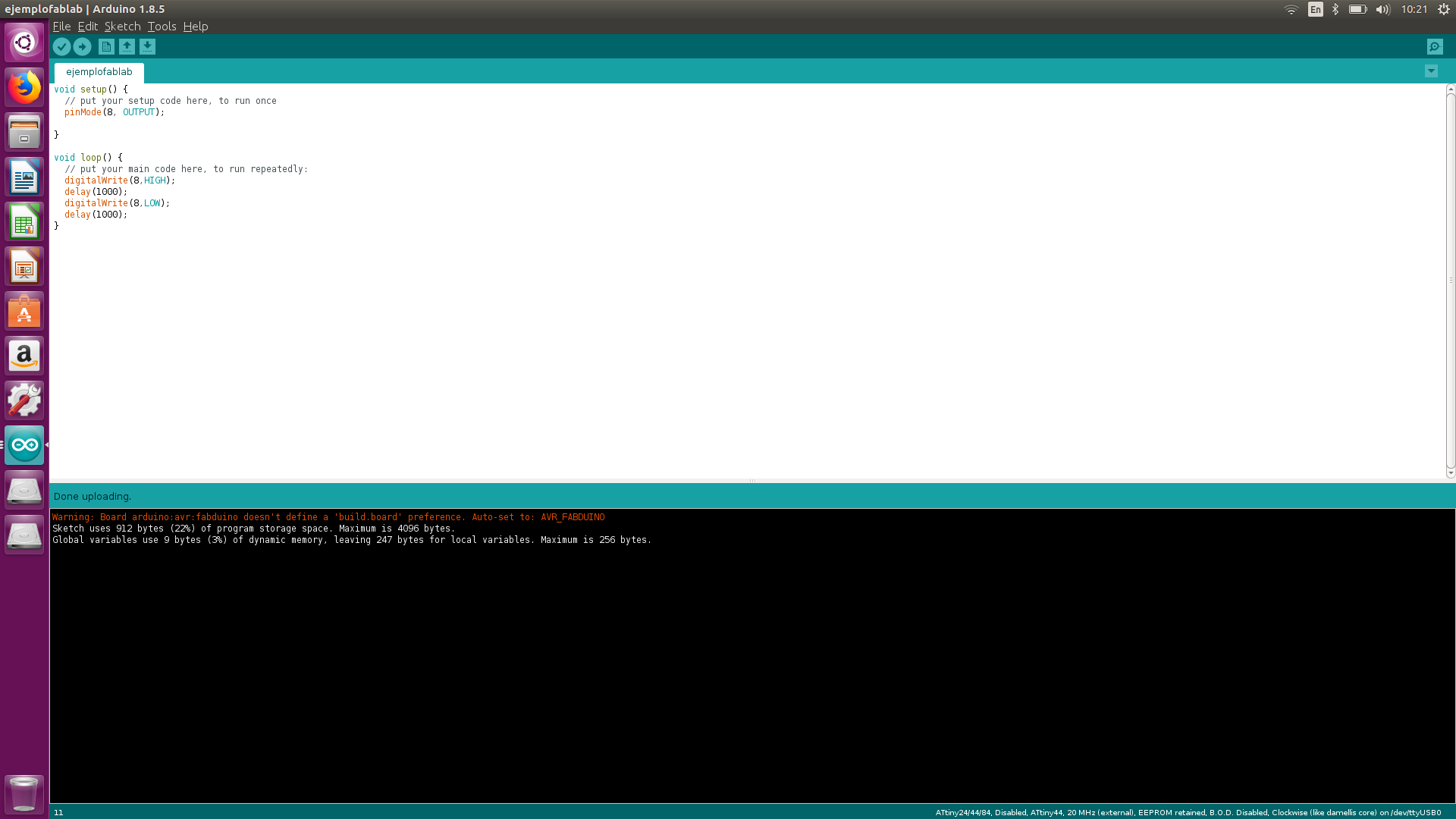
I have the LED connected to PB2, that is the 5th pin counting from top left. For arduino that is pin 8 so in the code I replace "LED_BUILTIN" with the right number.
Problem
I tried uploading several times but I always had this message. I didn't know what was going on.
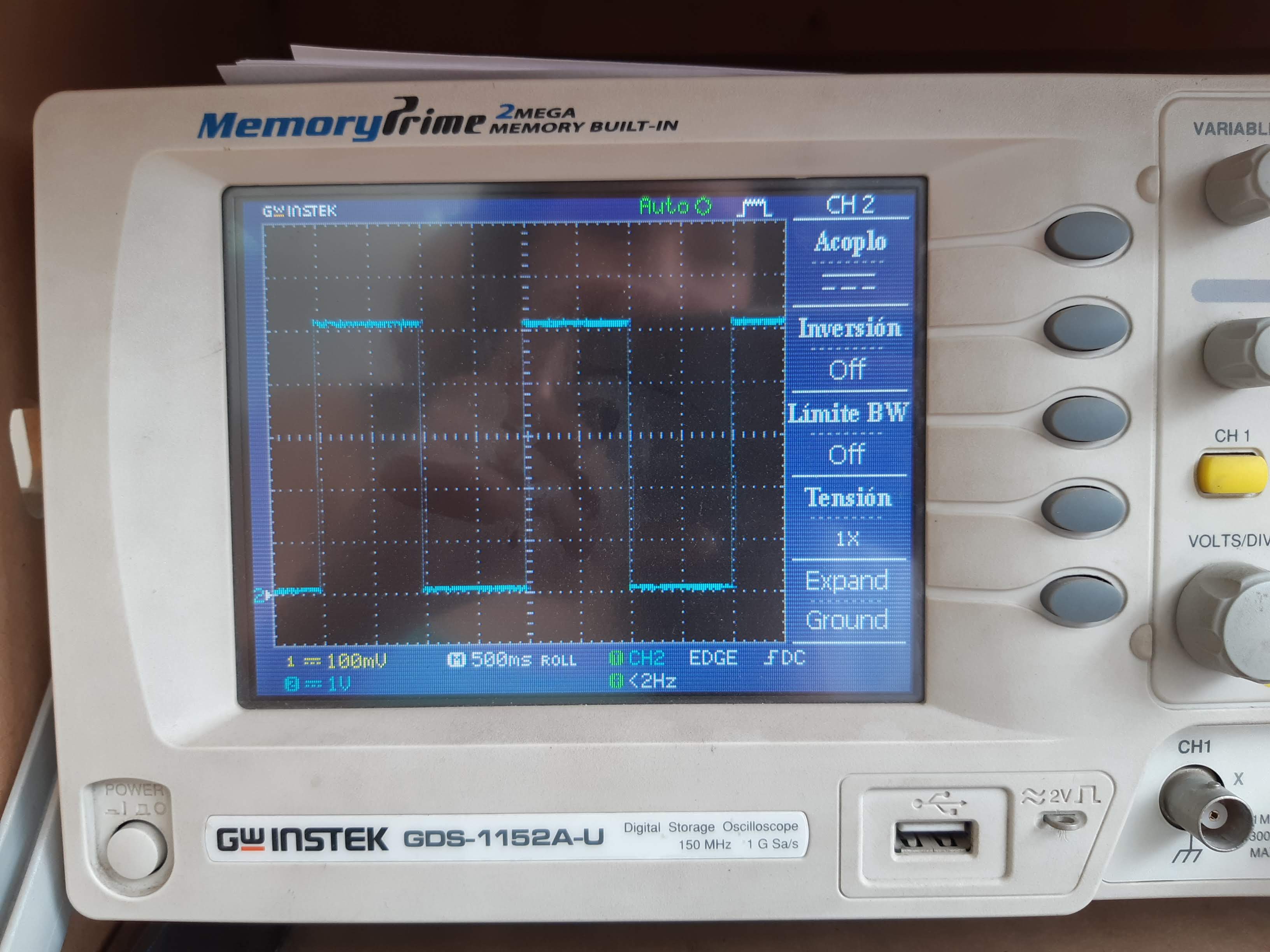
I spent quite some time with this issue checking my board and the connections, and I didn't realize that my board was working well until I checked it with the oscilloscope.
solution
After seeing this I had to check just the LED. First I tried turning the LED on with the multimeter, it wasn't working so I replaced the LED.
But when uploading the code it still did not work.
Then I tried turning the led around. Still nothing
After a while, a friend of mine suggested that I change the order of the led and it's resistor, and explain a little bit about common anode and cathode. I did as he said and tried again.
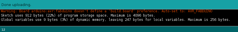
This time I got the same message, but...

It worked!
I talked with the instructors about what happened but they told me changing places between the LED and it's resistor wasn't the solution. Probably one of them was poorly soldered and when I switched their places I just did a better soldering.
Button
The button in this case, as you can see is a switch, and we have to program it with the internal resistor. First couple of tries were not successful, but I forgot to screen shot those attempts. Finally after doing some research on the Internet, exploring some arduino examples and with the help of some classmates, I finally came up with the right code.
Bingo!
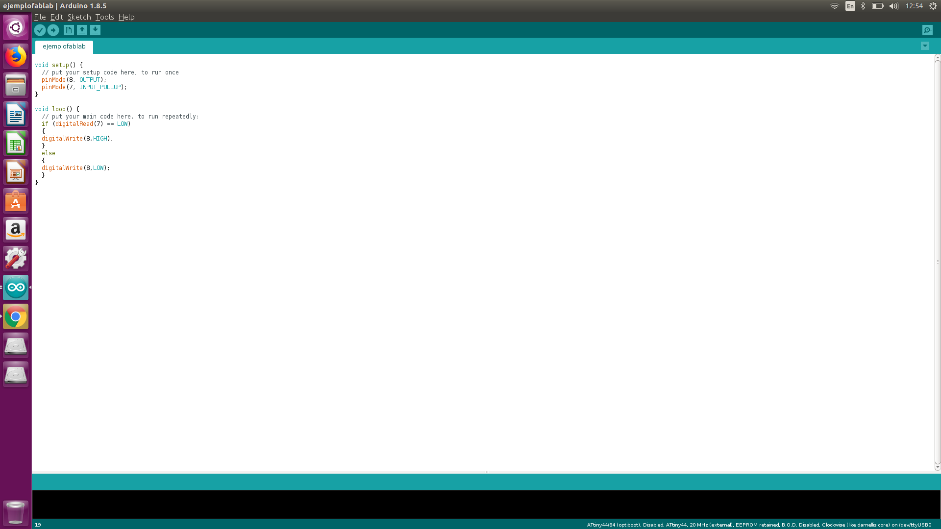
The next day I tried writing the code again to actually understand the logic of it, and add a delay.
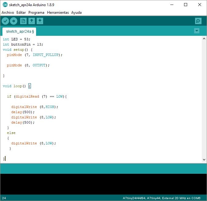
It worked!
Here you can copy the code I used.