Programs
The first question is: what computer-aided design programs do I already know?
| 2D (vector and raster) | 3D | video and sound editing |
|---|---|---|
| Inkscape | Google Sketchup | Audacity |
| Illustrator | Siemens NX | KdenLive |
| Photoshop | Sculptris | OpenShot |
| Gimp | Meshmixer/Meshlab | Premiere |
| Scribus | TinkerCad | Windows moviemaker |
| Indesign | Blender | |
| Fusion 360 | ||
| Onshape |
It seems that spending 7 years in the FabLab world, design school and both windows and linux payed of.
For the next assignment I'll focus Onshape as I named this my new 3D CAD program a few months ago. In
design school we learned working with Siemens NX, but as the license costs starts at $7500, I needed another CAD program.
By now I have a base in drawing in Onshape, but I still need to figure out how to draw parametric. So that was my challenge this week.
As said above, I've already spend my fair time learning programs to do CAD design. Some of them I still use (see programs in bold, some of them I use to teach, others I've left them for what they were.
For 2D I'm still going with Inkscape as this is the first 2D program that I learned and I never really adjusted to Illustrator during my time at school.
2D to 3D design: Development of the Velleman toolbox
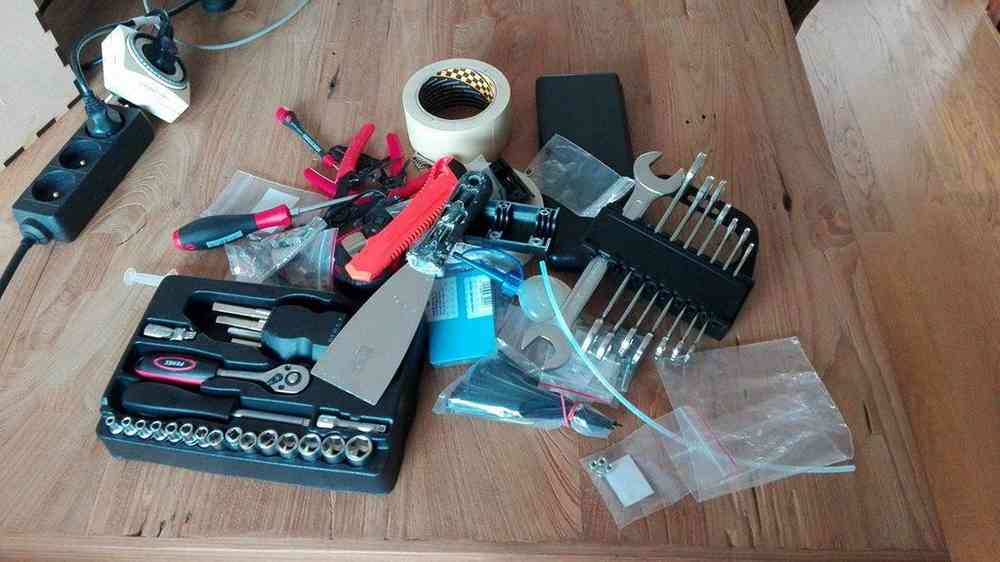
About 4 years ago I bought my first 3D printer. With the tools included. As I like to travel around Flanders (and the world) and the printer often joins me, it became hard to keep all the tools together. Therefore I wanted to make a little toolbox in which all the tools fit. It needed to be easy in transport, fit within the style of the Velleman Vertex, and of course host all of my tools.
I started out with a sketch in which I figured out how big the box needed to be, what the sizes are...
The old way
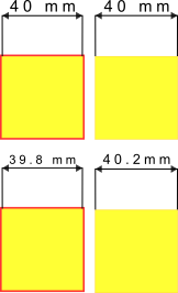
When I stared my FabLab career back in 2011, they learned me to make boxes with calculating the kerf of the machine into your design yourself. But maybe first some words of explanation:- Kerf: the kerf of the machine is the amount of material that you loose by cutting. When you lasercut wood you are burning away wood. While, when using plexiglass, you are melting away material.
- Boxmakers: as people figured out over the years that making boxes the old way can be quite slow, they started to develop boxmakers. Small plugins for CAD programs or webpages that allow you to easily make a box with tabs.
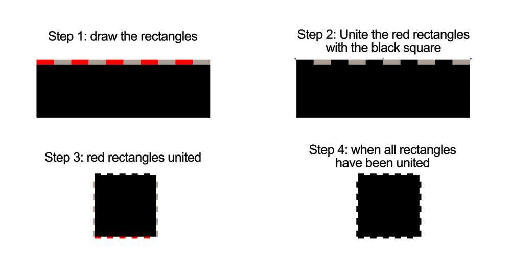
The old way basically exits out of a lot of rectangles, with the right size (kerf inluced) that are being put at the right place.
- draw the rectangles with the right dimensons
- copy/paste/duplicate the right amount
- put them at the right place
- use the align tool to level everything out
- Use the boolean 'unite' to connect everything to the main square
- Done!
The new way
The new way however is pretty easy. There used to be a plugin for Inkscape, but it stopped working some years ago. As I was searching for it,
I saw that someone modified the version to go with the newer versions of Inkscape: You can find it here.
As the plugin was not working ofr a few years, a lot of other websites started to offer the service of boxmakers. A list:
- MakerCase. The kerf can be found later in the proces, but it easy to look over.
- Boxdesigner
- For Fusion
- The elliptical boxmaker developed by one of my friends in FabLab Leuven (BE)
Back to the Velleman toolbox
The Velleman Toolbox was made in Inkscape by using both techniques. The main boxes (the big one and the smaller toolboxes) were generated with a boxmaker. So that leaves the lids and shelves.
The lids
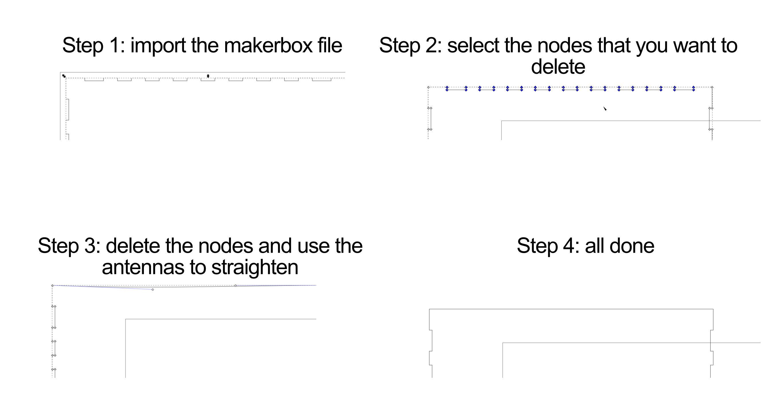
The lids that I have in my box, and the front of my maintoolbox have straight edges. I used the technique described below to make this. There are, however other options to do this (cut the lines open, delete it and add an new one through the node functions)
The shelves
For the shelves I used the same technique as described above. I made little squares, thickness the same as the wood +0.2mm and with tabwidth +0.2mm. As those would be the holes where my shelve would be pushed in.
The link to the files can be found in this instructable
3D design
For 3D design I have a lot of project to choose from, from the past years. But as most are made in Siemens NX, I needed to find something new. I decided to finish up a part of my bachelor thesis for which I didn't have time anymore: the MakerUnit for milling! More about that during the computer controlled cutting week.
Parametric design in Onshape
As I'm running ahead of the assignments for now, I decided to use this week to learn how to draw parametrically in Onshape. I've not mastered every single aspect of the parametric design
in Onshape, and there are a lot of functions that I know of, but that I'm not going to talk about here as they are not usefull to me right now.
Drawing parametrically in Onshape can be explained in about 4 steps (for Lego-blocks). I didn't find a lot of tutorials about this online, next to some of Onshape itself, so I decided to add
my own, you ca find it at the end of this 'chapter'.
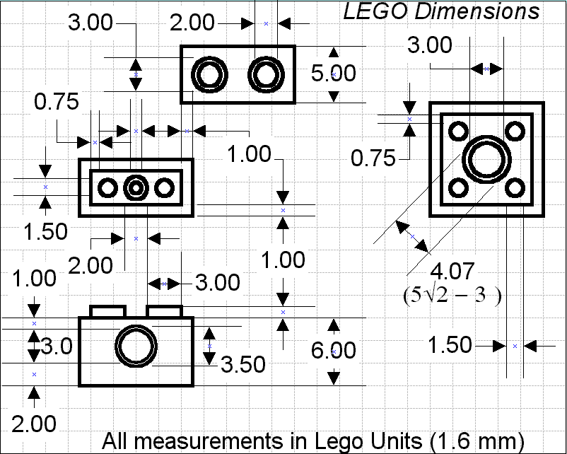
- 1. Define the dimensions of a Lego-block
- 2. Define your parameters in Onshape
- 3. Draw the sketch
- 4. Pattern as you wish
To do this you'll fine a small little icon in the toolbar that says : (x). Click on that one and make new parameters. Be careful not to use spaces but underscores if you want to name something and give useful names.
The only special thing here is that instead of giving fixed numbers as a dimension, you refer to the variable parameters that you made before starting the sketch.
One of the things you need to watch here is that you use the right linear pattern. Go for 'feature' pattern as you only want to copy a feature, not the full block. Follow the
GUI on what you have to do next and you'll have a nicely patterned Lego-block.
If you want to change your Lego-block now, you can adjust the width, height and amount of taps on top of the block.
If interested in a more detailed manual, you can find the full parametric manual for Lego-blocks here.
Digital sketches for my Final project
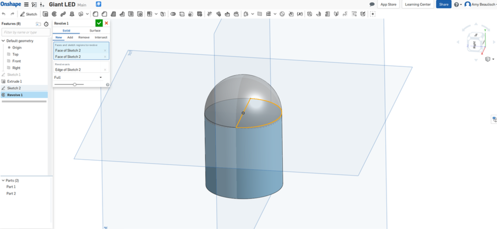
My new skill in this piece is to use the revolve function within Onshape. Contrary to the revolve function in Siemens NX, this one is pretty forward and the icon is right next to the extrude function
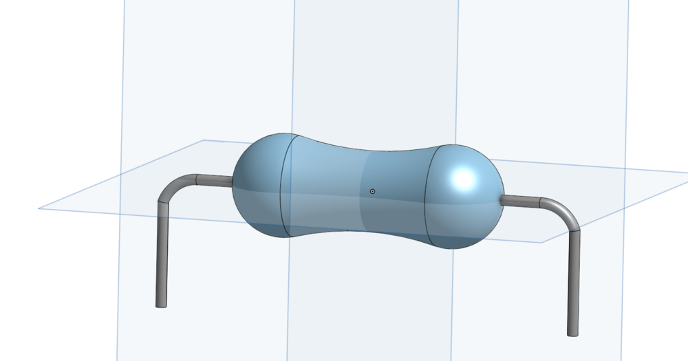
My new skill in this piece is to use the sweep function within Onshape. The first step to use this is to draw the plane on wich you're going to sweep, in this case the circular form. Second is t draw the lines that the sweep function has to follow. And the last step is to combine step 1 and 2 into the sweep function. I used the sweep function to make the legs or the resistor.
The next part to draw is the giant teacher breadboard. The size is around the size of a A0 paper and can be folded in 2 between the conductive lines. The idea is to have the jumperwires connected to conductive buttens so that we can push them on the board.
As this is all very basic for now, I decided to take a look at the 'make something big' project.
Sketches for the 'make something big' project
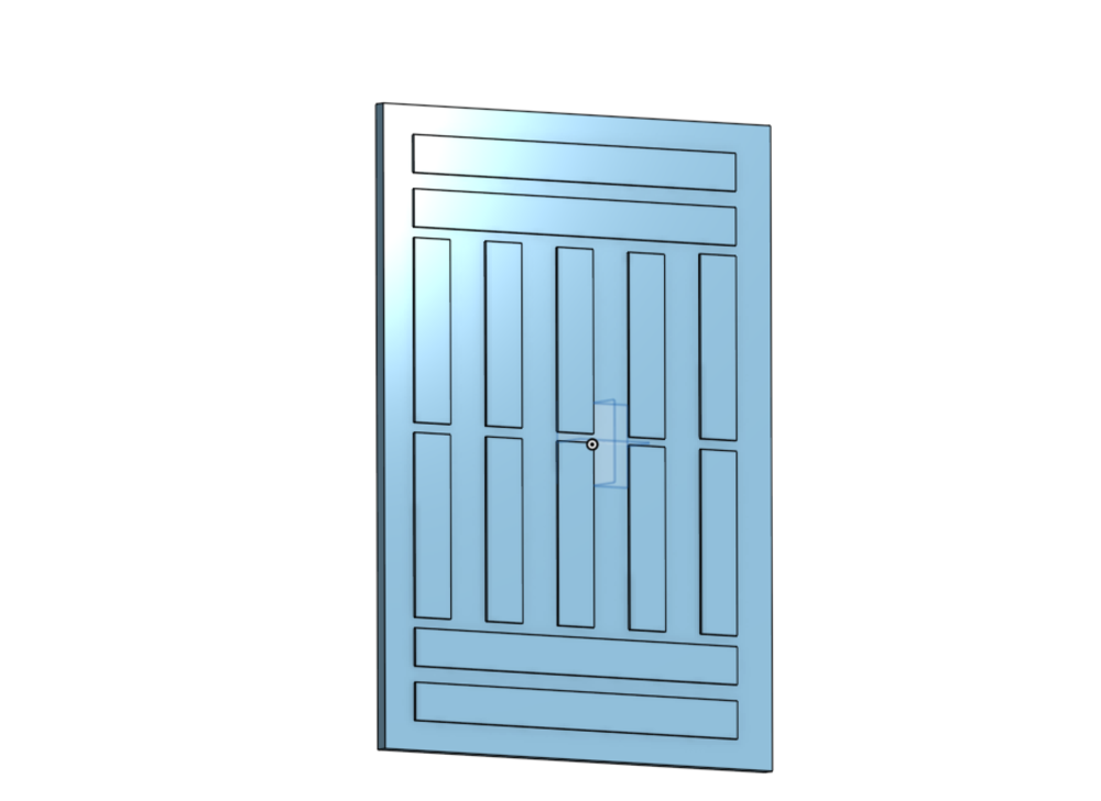
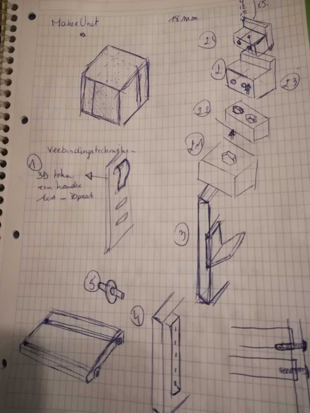
Back in the academic year 2016-2017 I graduated as a Industrial Product Designer. As my thesis I developed a MakerUnit. Or as we often describe it: a table for children in a FabLab. All the necessary tools fit into it, but also a nice height for kids to work on, modular and transportable. As we have been using version 1 (or 15 depends on how you see it), for about 2 years now, we noticed several small things that could have been done better. Another thing was that I didn't find the time and right persons to help me mill out the tables on a big CNC milling machine. So this is my chance!
One of the things that we had doubts about, was the connection for the plates on which the boxes would stand. We've had a lot of discussions and decided to give T nut's a try. It works, but it's time intensive. Our biggest fear is that the connections won't hold up all the tools that are stacked on them. In the next weeks I'll make a testing box to test out all the 'new' techniques to keep the plates in place.
One of the things that we are mising is the adaptability of the Units. We mostly use IKEA Samla and very useful boxes. And though they are almost the same shape, they still differ a bit.
I made the file parametric this time so that we can adjust things fast and without to much work.

note: files will be added once fully completed during the next weeks.
Reflection on this week
I combined the 'computer-aided design week with the computer-controlled cutting week. Back in 2013 it was a logical choice to have those two subjects separated. But as I grew over the years
it's really hard now to see it separated. So I took them together.
It didn't stop me from learning new stuff and pushing my boundaries. So on pushing my boundaries: I learned how to draw parametrically in Onshape. Which, for me was a big step. I was also
surprised to find so little material about it online, so I decided to make a manual myself. Next to that, I had a pretty easy week. Used a lot of known skills and experimented on on things
that have been lingering. On this point I'm referring to the electronics in the vinyl cutter, the MakerUnit that is getting a version 2.0.
I'm also happy to see that with limited time, read 3 evenings in a week and 1 day of a weekend, I'm able to do quite a lot: brainstorm, experiment, work it out, test it and document.
On frustration level, this week was calm. No intentions of laptop throwing or asking friends for help and buying them over with food.
Not sure if I can, but I feel proud of myself after this week (in which I completed 2 Academy weeks), but I do.