Individual Assignment:
Design and 3D scan and print an object (small, few cm3, limited by
printer time) that could not be made subtractive.
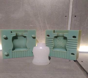
The 3D Modeling, Scanning & Casting prototypes for the social
challenges is recurring worldwide competitions organized by multiple
players in the ecosystem to foster innovation and empower young
talents by combining Design, Engineering, and Software. Design the
object in 3D, and make a prototype using 3D printing. You can also
research open source hardware such as Arduino, WeIO, Raspberry Pi, or
any similar electronic platform using them on a proprietary circuit
board. The aim is to create a 3D model with at least 2 parts by
imagining my creation, so that the final object is 3D-printable. The
goal is to highlight the different possibilities of 3D printing.
Group Assignment:
3D printing is a type of additive manufacturing
method, meaning objects are manufactured by adding material layers. 3D
printing allows complex shapes to be created, as well as reducing the
amount of material waste generated from the manufacturing process.
There are different types of 3D printer technologies, but for the
purpose of a Fab Lab (non-industrial level material quality needed,
small batch production). We have used FDM (Fusing Deposition
Modeling).
The 3D printer uses plastic filament from ABS, PLA, nylon and rubber.
Extruding the plastic filament through a nozzle, the material arrives
on the heated bed. The nozzle moves in X and Y axis. When one layer
finishes printing, the nozzle continues to print the next material
layer, building up the material in Z direction to create the object.
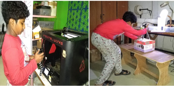
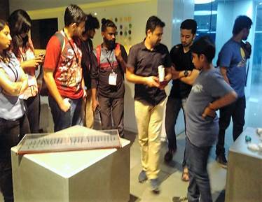
These are the two 3D Printers available in our Fab Lab. The Instructor
gave us an introduction to the 3D Printers we have at Fab Lab O. First,
we changed the previous plastic filament. The durability of the filament
varies depending on the environment of the place.
Before printing, we have removed the print bed from the printer and
cleaned its surface with a blade to remove the plastic filament and glue
from the previous print (the printing bed can be also cleaned with a wet
sponge). After putting the print bed back into the printer, we have
applied a layer of paper glue lightly, which support the first printed
material layer.
After the .stl file was loaded, the 3D Printer began to print.
 The Testing Design Rules with a Testing Kit downloaded from
thingiverse website -
The Testing Design Rules with a Testing Kit downloaded from
thingiverse website -
I downloaded a simple test kit from Thingiverse to test the 3D Printer
using a higher quality print setting.
Quality - layer height – 0.1mm
Fill Density – infill – 30%
Support – Yes
Raft - Yes
Some of the test findings (testing the design rules) :
- Wall Thickness:
0.1 mm (failed), 0.2 mm (failed), 0.3 mm (failed),
0.4 mm (ok), 0.5 mm (ok), 0.6 mm (ok), 0.7 mm (ok)
- Holes:
Size 3 mm, 4 mm, 5 mm
(shape is not so round, internal wall contain some residue)
- Bridge:
Print: 2 mm (ok), 4 mm (ok), 8 mm (ok),
16 mm (failed)
- Overhang of 25, 30, 35, 40, 45, 50, 55, 60, 65, 70 degrees all are ok.
The Testing Design Rules of a 3D Printer –
- Place object on the platform.
- Secure it in position as the platform will be rotated during the
3D scanning process.
- Click the "Scan" button at ScanStudio software.
- Ensure the object is in the position as shown on the screen.
- When the 3D scanning starts, the 3D Scanner shot out multiple
light beams onto the object while the rotating platform will
automatically rotate the object around. The 3D scanning process took
about 50 minutes or longer.
- Use the "Trim" tool of ScanStudio to remove unnecessary portion
like the platform and the overhung securing bar.
- Use the "Fill" tool of ScanStudio to fill up holes. The software
will automatically detect and highlight the holes.
- Exported the 3D model from ScanStudio to a .stl file and imported
into Fusion 360.
- However, I seem to miss out on "filling" all the holes. I might
have to go back to the Fab Lab and use ScanStudio to fill the holes
again, or I might use professional software like Blender or Autodesk
MeshMixer to touch up the model.
Individual Assignment – 3D Scans – The 3D scanning
technologies turn atoms into bits. There are many types of scanning
technologies available on computer or on smart phones. The one that is
used at Fab Lab O is an infrared depth map scanner. For 3D scanning or
three-dimensional capture, what an expensive professional 3D scanning
equipment and/or software used to do is now accessible to the consumer
with the arrival of 3D scanner mobile app. Expensive 3D scanning
equipment use to shot hundreds of depth-sensing beams on the object,
while 3D scanning mobile apps are based on photogrammetry which is a
technology whereby a 3D model is created out of multiple 2D photos.
 Brief process to 3D Scanning:
When the 3D Design is ready, it is then exported in the .STL format for
its impression.
Step 1: Gather data (acquisition sequence - data is captured by
following a very specify sequence of movement)
Step2:Analyse captured data and processing
Step3:Retouching (touch-up on small anomalies)
Best practices :Avoid object with reflective areas will
result images having lots of abnormalities that very hard to repair. The
areas without textures are too smooth to scan.
3D Scanning - There are two ways to acquire the bits
of an object, either the scanner remains stationary (mount it on a
tripod when scanning a person) when the object rotates, or the object
remains stationary when the scanner moves. Direct sunlight needs to be
avoided, since it interferes with infrared light. The camera we use for
scanning at Fab Lab O is Kinect (Microsoft Xbox). Once the device
is connected to the computer,open Skanect, a free 3D scanning
software (pro version comes with more high quality scan is also
available).
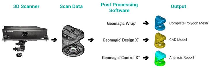
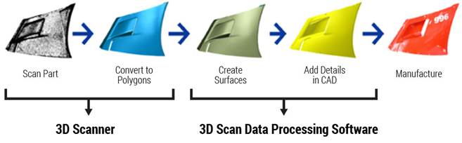
A 3D scanner is a device that collects physical data of an object or
environment in order to create a digital model. This data can include
volume, texture and color. There are two main types of 3D scanners:
contact or non-contact. The 3D scanning is the process of analyzing a
real-world object or environment to collect data on its shape and
possibly its appearance for example color. The collected data can then
be used to construct digital 3D models. A 3D laser scanners create
“point clouds” of data from the surface of an object, by capturing a
physical object's exact size and shape into the computer world as a
digital 3-dimensional representation. A 3D point cloud is a set of data
points in space. The Point clouds are generally produced by 3D scanners,
which measure a large number of points on the external surfaces of
objects around them.
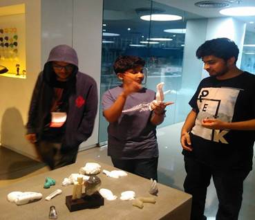
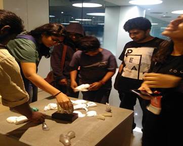
We have a ‘Sense’ 3D Scanner in our Fab Lab.
I have joined My Team Mate Pooja for this task.
http://fabacademy.org/2019/labs/vigyanashram/students/pooja-jadhav/Assignments/index%206.html
Later My Team Mate Aditi also requested me for help, so it was a good
experience to experiment with the 3D scan for a second time.
 http://fabacademy.org/2019/labs/vigyanashram/students/aaditi-kharade/assignment6.html
Issue –
http://fabacademy.org/2019/labs/vigyanashram/students/aaditi-kharade/assignment6.html
Issue – I tried experimenting with this, but the
software got corrupted and there was an issue with the 3D scanner. Hence
couldn’t do it.
The 3D scanning is Reverse Engineering Process and vital in Geo Spatial
Analysis.
My experience at the Clark Planetarium, Salt Lake City, Utah – During my
stopover at Salt Lake City for a night stay, while returning from the
University Rover Challenge 2019 from Mars Research Desert Station,
Hanksville, I visited The Clark Planetarium. Sharing my experience of
the Infrared Waves, which is quite similar to the 3D Scanning procedure.
 Photogrammetry –
 I wanted to explore on
Photogrammetry. As I was Browsing, I understood the following concepts.
Photogrammetry is the art and science of extracting 3D information from
photographs. The process involves taking overlapping photographs of an
object, structure, or space, and converting them into 2D or 3D digital
models. Photogrammetry is often used by surveyors, architects,
engineers, and contractors to create topographic maps, meshes, point
clouds, or drawings based on the real-world.
OpenMVG is a library target for photogrammetry, finding great use for
the Multiple View Geometry (MVG) community. The emphasis appears to be
on the structure from motion technique of photogrammetry, with a number
of the integrated tools built around this. A photogrammetry pipeline
that requires compiling to use, OpenMVG takes some computer savvy to get
up and running on Windows or Linux.
Designed around the mantra of “Keep it simple, keep it maintainable“,
the community-focused accessibility of OpenMVG makes it an accessible
tool that fits into the workflows of other photogrammetry tools.
Applications of Photogrammetry Software –
1. Building Design and Renovation.
2. Digital Preservation.
Different Types of Photogrammetry -
The way photogrammetry software usually works is the following. First,
the program automatically registers the shared points between every
image and then calculates the distances between them in 3D space. The
result is a point cloud that you can transform into a 3D mesh.
Photogrammetry is an ingenious technique for 3D scanning. You can
capture large objects like buildings or even mountains that would be
impossible to scan using other methods. Moreover, photogrammetry is also
extremely affordable since you probably already own the most important
piece of equipment: the camera of your smartphone. However, you also
need photogrammetry software to create a 3D file of the object you
have photographed.
Like many things, photogrammetry software comes in many shapes and
sizes. Major software developers have published commercial solutions
that are ideal for industrial and engineering applications. However, a
number of programs are available for free download. To help you find the
right photogrammetry software, we have assembled the following list of
titles.
There are two primary types of photogrammetry: aerial and close-range.
Like, BeMAGINE Photogrammetry, iWitnessPRO, Drone Deploy, Pix4D,
Photomodeler, Autodesk Re Cap, Reality Capture, Agisoft Metashape, and
3DF Zephyr.
Free Photogrammetry Software – Colmap, Meshroom,
MicMac, Regard3D, VisualSFM, and OpenMVG.
My Task for 3D Printing -
1. Exporting the model and prepare the mesh for 3D printing:
The scan quality should be good. Under Reconstruct/Remove Parts, these
parts can be removed automatically.
2. Filament: The filament used is PLA 2.85mm diameter 750 gram. PLA
is a sturdy yet biodegradable material. PLA stand for polylactic acid or
polylactide and is derived from renewable resources.
Then I saved the file in .obj format under Share, and opened it
in Mesh mixer, Autodesk software I used to edit and sculpt on my
model. There are several areas in the model that were hollow, since
these were the blind spots of the camera. This can be fixed
under Edit/Make Solid.
With Edit/ Transform, the size and the position of the model can be
determined.
With Edit/Plane Cut, the model can be cropped from different
angles. Similar to clay sculpting, a range of tools are available
under Sculpt for changing the form of the model.
Before exporting the file, make sure to select all the layers and click
on Edit/Combine.
I understood that the 3D Printing process is
3D printing or additive manufacturing is a process of making three
dimensional solid objects from a digital file. The creation of a 3D
printed object is achieved using additive processes. In an additive
process an object is created by laying down successive layers of
material until the object is created. Each of these layers can be seen
as a thinly sliced horizontal cross-section of the eventual object.
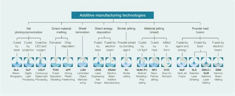
Since 2010, the American Society for Testing and Materials (ASTM) group
“ASTM F42 – Additive Manufacturing”, developed a set of standards that
classify the Additive Manufacturing processes into 7 categories
according to Standard Terminology for Additive Manufacturing
Technologies.
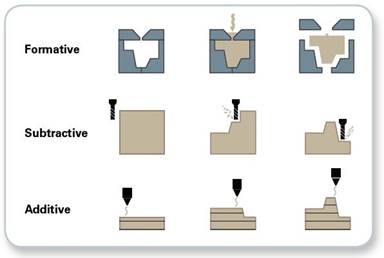
These seven processes are:
 Subtractive Manufacturing –
Subtractive manufacturing is a process by which 3D objects are
constructed by successively cutting material away from a solid block of
material. Subtractive manufacturing can be done by manually cutting the
material but is most typically done with a CNC Machine. It creates waste
from the material that is removed. It has limited design capabilities.
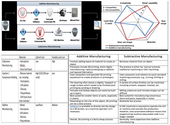
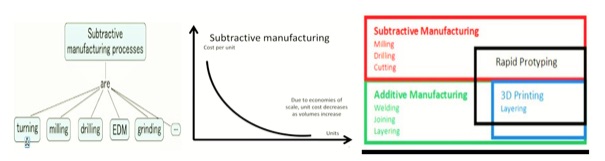 The differences between Additive and Subtractive Manufacturing –
 The Slicing Software –
The Slicing software is a necessary element of 3D printing, because 3D
printers cannot translate a CAD drawing by themselves. It will create
paths for a 3D printer to follow when printing. ideaMaker is a powerful
user-friendly slicing software that prepares STL, OBJ and 3MF files for
3D printing in just 2 clicks. It generates the machine code that the
printer will use for printing. Furthermore, the program defines a
cross-platform program that takes 3D files (STL) and generates path
information (G-code) for a 3D Printer.
| SL.No |
Software |
Function |
Level |
System |
| 1 |
Cura |
Slicer, 3D Printer Host |
Beginners |
Windows, Mac, Linux |
| 2 |
Matter Control 2.0 |
Slicer, 3D Printer Host |
Beginners |
Windows, Mac, Linux |
| 3 |
3D PrinterOS |
Slicer, 3D Printer Host |
Beginner |
Windows, Mac, Ubuntu, Raspberry Pi |
| 4 |
Astroprint |
Free |
Beginners, Advanced Users |
Windows, Mac, Ubuntu, Raspberry Pi |
| 5 |
CraftWare |
Free |
Beginners, Advanced Users |
Windows, Mac, Ubuntu, Raspberry Pi |
| 6 |
IceSL |
Free |
Beginners, Advanced Users |
Windows, Mac, Ubuntu, Raspberry Pi |
| 7 |
ideaMaker |
Free |
Beginners, Advanced Users |
Windows, Mac, Ubuntu, Raspberry Pi |
| 8 |
KISSlicer |
Free/$35 |
Beginners, Advanced Users |
Windows, Mac, Ubuntu, Raspberry Pi |
| 9 |
MakerBot Print |
Free |
Beginners |
Windows, Mac, Ubuntu, Raspberry Pi |
| 10 |
MatterControl |
Free |
Beginners, Advanced Users |
Windows, Mac, Ubuntu, Raspberry Pi |
| 11 |
Netfabb Standard |
$1000 to $4300(annual Subscription) |
Intermediate Users, Advanced Users |
Windows |
| 12 |
OctoPrint |
Free |
Intermediate Users, Advanced Users |
Windows, Mac, Ubuntu, Raspberry Pi, Linux |
| 13 |
Repetier |
Free |
Intermediate Users, Advanced Users |
Windows, Mac, Linux |
| 14 |
SelfCAD |
Free trail, $9.99/month |
Beginners, Advanced Users |
Browser |
| 15 |
Simplyfy3D |
$150 |
Beginners, Advanced Users |
Windows, Mac |
| 16 |
Slic3r |
Free |
Advanced Users |
Browser |
| 17 |
Tinkerine suite |
Free |
Beginners |
Windows, Mac |
| 18 |
Zsuite |
Free |
Beginners |
Windows, Mac |
G-code is a language that humans use to tell a machine as to “how to
perform a task”. With 3D printing, g-code contains commands to move
parts within the printer. G-code consists of G- and M-commands that have
an assigned movement or action. G-code is the programming language of
your 3D printer. Using G-code, a computer tells a printer when, where,
how to move and how much to extrude throughout the entire print process.
To import the file in Notepad++, go to Language > Define your
language, click Import.
I have used Fractal Works 3D Printer to model my design in belief that
My Design is My Creativity with a Purposeful Strategy.
You can check out more about the software at
http://fractalarts.com/ASF/Fractal_Software_Programs.html
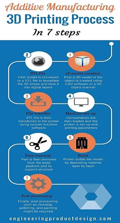
The 3D Printing Process I have followed – I have used Julia 3D Printer from
https://fracktal.in/julia-series/
 https://fracktal.in/how-to-succeed-with-printing-pva-soluable-support/
Step 1 – 3D model creation - I have made a 3D model of the object is
created using CAD software.
Step 2 – STL file creation - Then I have converted the CAD model to a
STL file to tessellate the 3D shape and slice it into digital layers.
Step 3 – STL file transfer - I have transferred the STL file to the
printer using custom machine software.
Step 4 – Machine set up - The PLA Consumable was loaded by me and I had
the printer set-up with the printing parameters.
Step 5 – Build - The Printer built the model by depositing the material
layer by layer to print my design.
Step 6 – Part Removal - Lastly, I have removed the parts from the build
platform and its support structure.
Step 7 – Post processing - Finally, post processing, cleaning was done
by me to ensure that the next user finds it intact and ready for use.
Why it is not made by subtractive manufacturing?
Subtractive manufacturing or subtractive fabrication involves cutting away from a solid block of material. It could be a block of, for example, metal, plastic, or wood. The manufacturing processes is based on controlled removal of undesired materials through cutting, drilling or milling to achieve the desired forms. Since this design contains small holes, overhang and mesh, the overhang and mesh of the Mobius geometry cannot be subtractive printed, hence I did not choose this method for 3D printing. The 3D printer can print better than any milling machine. While taking the curve parts into account the 3D printer can do a good job, and in some cases, support removal is needed in a few cases depending upon the design, which is not affordable with any other milling machine.
Software Used – Auto Desk Fusion 360.
The 3D printed Temperature Holder was designed during the Computer Aided Design Assignment as shown below and was printed during this Assignment as shown below.
http://fab.academany.org/2019/labs/vigyanashram/students/hemang-vellore/Assignment3/A3%20Computer%20Aided%20Design.htm
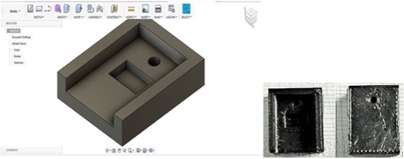
Design File - A3 Computer Aided Design_files\lm35 v2.f3d
The Solar FAB Air Cooler Body design and 3D printing process is shown below.
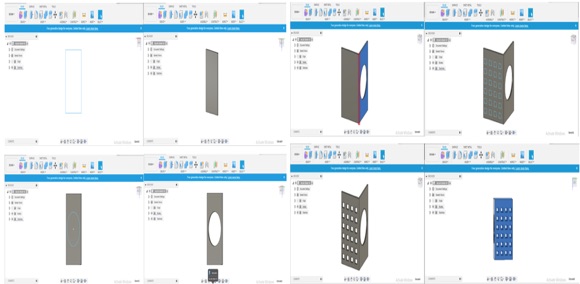
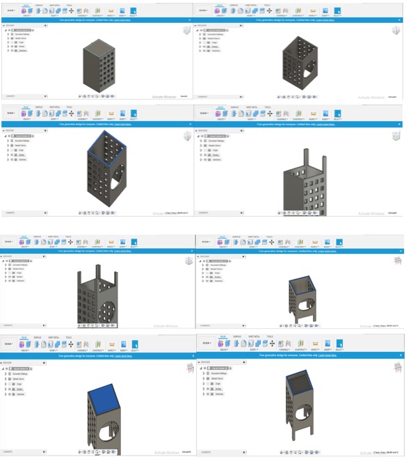
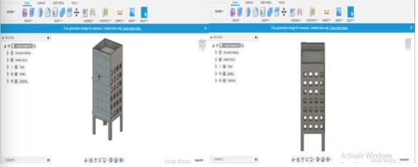
Design File -
A6 3D Modelling, Scanning and Printing_files\my air cooler.stl
Video link -
https://youtu.be/ESNITVuf6QY
You can see the time taken for 3D printing this design. Now my prototype
is 100% 3D printed.
After completing My Final Project, I have taken this picture to ensure
that My Prototype stood good.
I have also made a Temperature Sensor Holder for my final Project here –
Assignment 3 Computer Aided Design
http://fab.academany.org/2019/labs/vigyanashram/students/hemang-vellore/Assignment3/A3%20Computer%20Aided%20Design.htm
My visit to Imaginarium – India’s largest 3D Printing Company – https://www.imaginarium.io/
I have visited Imaginarium during my stint at the STEAM School, Bonjour
India at Makers Asylum, Mumbai, India in December 2017.
 Learning Outcome –
 I have learnt about 3D Design
software using AUTODESK Fusion 360. The process is very engrossing. I
understand that the 3D Scanner has to be held upright properly in order
to get a perfect scan. I have experienced the effect of Infrared Sensors
in real life. I have successfully 3D printed the Prototype for my Final
Project and a Temperature Sensor Holder for my final project – Smart FAB
Air Cooler.
Reference – FAB Academy Tutorials
www.thingiverse.com
https://my3dtwin.com/how-3d-printed-figurines-are-made
https://all3dp.com/1/best-photogrammetry-software/
https://www.autodesk.com/solutions/photogrammetry-software
https://all3dp.com/1/best-3d-slicer-software-3d-printer/