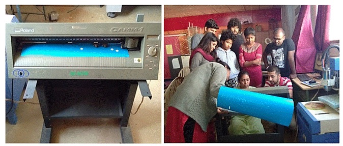
Group Assignment demo for Vinyl Cutting:
A computer controlled plotting device with a blade instead of a pen. A vector based design is created in a software program (usually Adobe Illustrator or Corel Draw) and then sent to the cutter where it cuts along the vector paths laid out in the design. The cutter is capable of moving the blade on an X and Y axis over the material, cutting it into any shape imaginable.
Since the vinyl material comes in long rolls, projects with significant length like banners or billboards can be easily cut as well. The one major limitation with vinyl cutters is that they can only cut shapes from solid colors of vinyl. A design with multiple colors must have each color cut separately and then layered on top of each other as it is applied to the substrate. Also, since the shapes are cut out of solid colors, photographs/gradients cannot be reproduced with a standalone cutter.
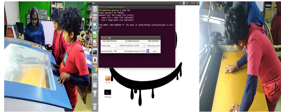
We used the fab modules, to interface with the cutter. Fab modules can use or downloaded for free from the mods - Fab website. To run the module, use the sudo Fab command. Then put the password and press enter. Then I have selected image (.png). Next on the Roland Vinyl Cutter (.camm) then clicked on make_png_camm.
Individual assignment: Make something. I made a laptop sticker of my company’s logo using Inkscape
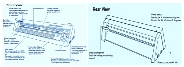
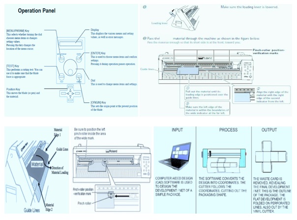
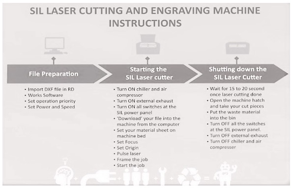
These infographics talk about the machine and the process.
I made a laptop sticker of my company’s logo using Inkscape -
A4 Computer Controlled Cutting_files\logo.svg
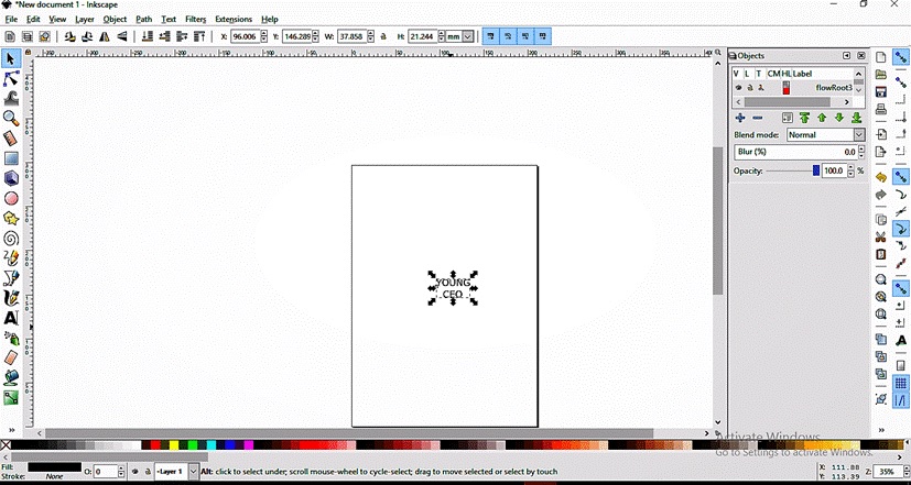
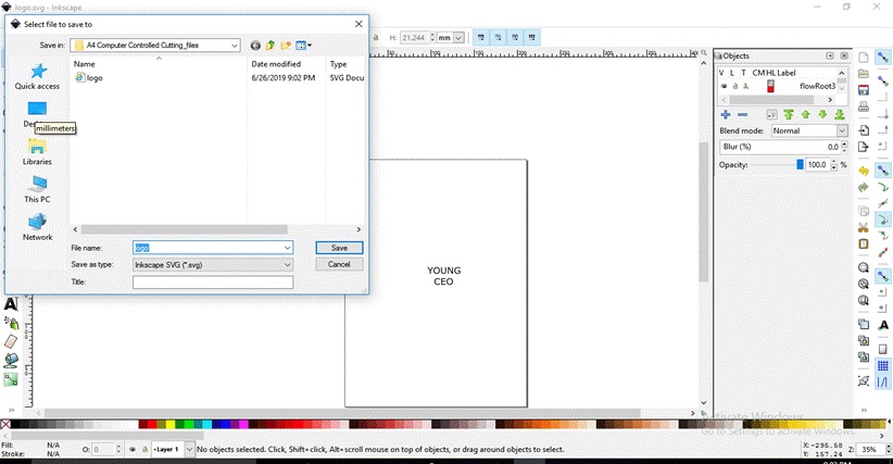
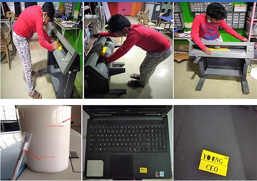
The Vinyl Cutter used a computer controlled blade to cut out the different shapes into stickers.
It can also cut copper tape for circuit traces which can work as PCB’s. I ensured that the Vinyl Cutter files contain Vectors in lines without any fills within the area of the document.
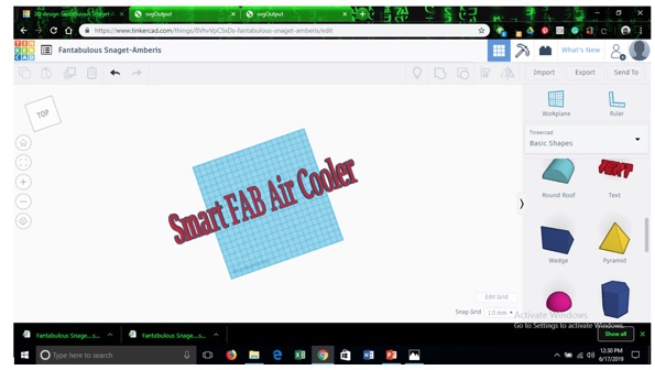
I tried this out for my final project.
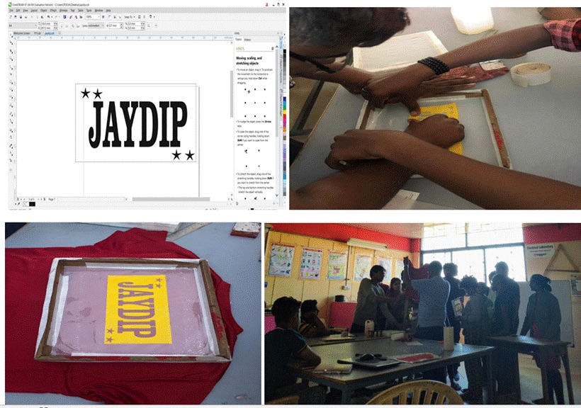
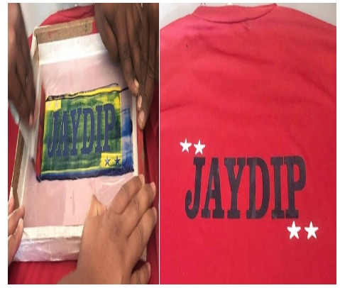
Group Assignment - Fabric PrintingThe Faculty has demonstrated the procedure of Fabric Printing to our Group. They have used Corel Draw and Plotted on the Vinyl Cutter. The Instructor pasted it on the palette block, which was a DIY frame with polyester cloth fitted in a wooden frame for printing it on the T shirt. He inserted a card board under the T shirt to avoid the paint sticking on the reverse side. Then he filled in Blue color for the name and white for the stars alternatively using a cello tape to block the colors. The trick lies in how best we use the pressure and fabric paint to get the print right. He also demonstrated using kerosene on how to clean off the color from the block. Though the design was visible, he said that the pores of the cloth must be clear to be reused again.
 Laser Cutting
This technology uses a laser to cut the materials and is typically used for industrial manufacturing applications, also being used by schools, small businesses, and hobbyists. Laser cutting works by directing the output of a high-power laser most commonly through optics. The laser optics and CNC (computer numerical control) are used to direct the material or the laser beam generated.
The Laser cutters work by directing a very powerful laser beam, at a precise focal length, onto a material which they either cut or etch, depending on how the laser cutter has been set up. Laser cutters cut materials similarly to other computer controlled tools, only they do so using a beam of light as opposed to a blade. When laser cutters are set up to etch something on the surface of a material, they operate like a printer, literally using their laser beam to etch an image onto something.
There's two different cutting techniques you can employ when using a laser cutter, Vector and Raster.
Raster tends to be used for engraving things, while Vector is much more adept at cutting things out.
A typical commercial laser for cutting materials would involve a motion control system to follow a CNC or G-code of the pattern to be cut onto the material. The focused laser beam is directed at the material, which then either melts, burns, vaporizes away, or is blown away by a jet of gas by leaving an edge with a high-quality surface finish. Industrial laser cutters are used to cut flat-sheet material as well as structural and piping materials.
 Hardware for Laser Cutting/Etching -
Cast Acrylic - can be etched and cut (has a nice frosted appearance).
Extruded Acrylic - can be cut (does not frost when etched).
Laser safe plastic such as ABS and polycarbonate - can be both etched and cut.
Anodized Aluminum - can be etched (Black anodized aluminum provides best contrast out of all anodized aluminum)
Brass - Un-coated brass cannot be etched with a laser, it needs to have some kind of coating (such as paint).
Glass - Can be etched. This includes bottles (both full and empty) drinking glasses, and plain flat glass.
Requires a more special technique to etch well.
Wood - can be both etched and cut
A word of caution - Too High of a power can distort engraved images.
Software for Laser Cutting/Etching -
In addition to the laser cutter and materials you plan to cut, is a computer with some form of vector graphics software loaded onto it. The most commonly used tools for designing are Inkscape, SketchUp, Corel Draw. But can use any software which can be easily converted into RD Works.
Caution – Advised to be cautious about the Laser Radiation when open. Do not stare or view into beam while the process is on, especially with optical instruments. Acrylic, Wood, Paper, Plastic, Laptops, and a whole host of other things are flammable, so please don't walk away mid cut. Never lean on the honeycomb bed platform inside the machine as the honeycomb platform is not strong enough to support body weight.
Parametric Modelling –
The parametric modelling involves the building or design of 3D geometrical models piece by piece. The process usually starts with a 2D sketch followed by the integration of constraints, dimensions and entities to form a defined 3D model. These constraints, dimensions, and other entities are known as parameters.
It’s also observed that the direct modeling helps engineers define and capture geometry, which is an excellent integration with manufacturing processes, resulting in a decrease in production time. The Parametric models take more time to update. With parametric modeling, you capture design intent using features and constraints, and this allows its users to automate repetitive changes, such as those found in families of product parts.
Pros of Parametric Modelling:
Automatic updates to the model if changes are made to the design.
The ability to easily capture design intent, which makes it easier to define how the model should behave when something is changed.
Easy definition and automatic creation of families of parts.
Excellent integration with manufacturing processes, resulting in a decrease in production time.
But parametric technology is not without its drawbacks. Some of the cons associated with parametric modeling include the following:
Cons of Parametric Modelling:
During concept design, parametric 3D CAD may be overkill for designers trying to investigate as many 3D concepts of an idea as quickly as possible.
Parametric models take more time to update when unexpected design changes are needed.
Group Assignment:
Our Batch was divided into 3 groups. The different materials were allotted to each of the groups. We tested on Cardboard, MDF and Acrylic.
I have teamed up with Manoj and Pooja for Cardboard Laser Cutting. There is a SIL Laser Cutter in our Fab Lab.
We have designed a 40 X 30mm rectangular shape. Then tested 4 squares at different Speed between 30 to 45 power ranging from 65 to 80.
The best result we obtained was when the Speed - 40 and Power - 72, where the kerf achieved was 40mm width kerf was 0.4mm and 30mm height kerf was 0.29mm.
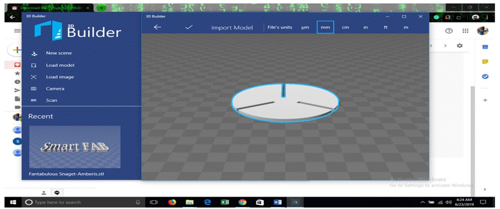
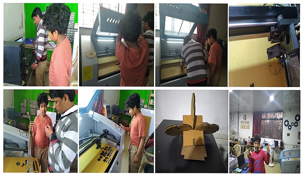
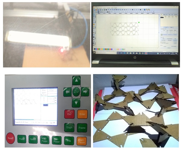
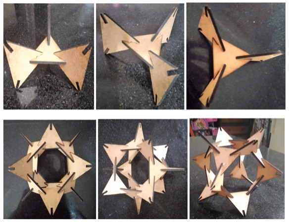
The object can be made in any software and has to be saved as .dxf file. Then import the file in RD works. RD works is machine software which controls the Speed and Power. We can also set different Power and Speed variables for different objects by using different colors. Given the Speed and Power for cutting and scanning, downloaded it. We have tried out 4 pieces first as demo and then tried cutting 4 pieces of cardboard as shown below.

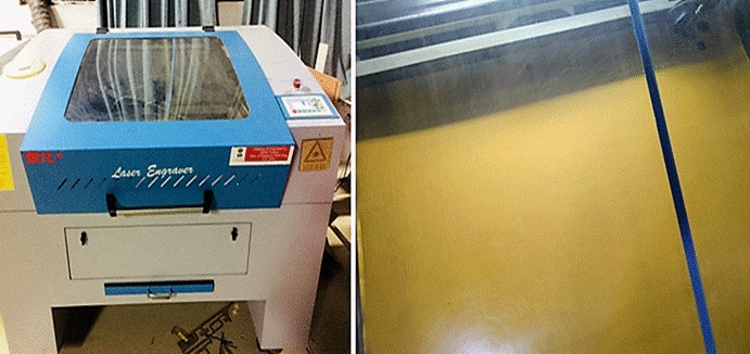
Laser Cutter Machine and Process
Our Fab Lab has two types of laser cutters, SIL laser cutter and epilog laser cutter. So, we have used SIL laser or CO2 laser cutter which is having a 600*900mm bed area and can cut materials up to 12mm. The software connected to it is RD Works. For importing any file this software we need to convert the file into (. dxf). The cutting, engraving and Scanning speed and power can be changed accordingly. Kerf is the portion burnt away by the material when it cuts through by the Laser on the Laser Cutting Machine. It is called as the Laser Kerf ranging in Millimeters.
We have used a 2.06 mm Cardboard. We then checked the kerf of each part. We have faced a problem where only 2 squares were cut because of the low speed and power and other two were cut properly.
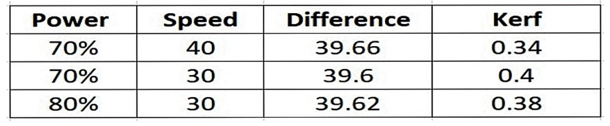
This kerf was checked horizontally measuring 39.60mm out of 40mm so here the kerf was 0.4mm. This kerf was checked horizontally, which is 29.66mm out of 30mm so here kerf was 0.34mm, thus characterizing our laser cutter’s focus, power, speed, rate, kerf, and joint clearance respectively.
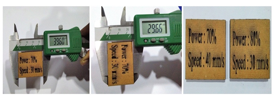
Here the table of difference and kerf.power 65 and speed 45 is not cutting well, that's why I am not adding kerf.
 Issue –
 When we tested the laser cut parts with different speed and power, it was burnt a little bit as seen above, as the engraver had a very high amount of kerf lining.
Solution - The Power setting determines exactly that. You can control how much power will be applied to the laser while printing. The more power- the more heat, and the more heat- the greater the chance of fire.
The Speed you choose, determines how fast the laser will travel while cutting. The slower the speeds, the longer the laser sits in each spot, which yields more heat and I think you see where this is going. It also means that the slower the speed, the deeper the cut or engraving will be.
Individual Assignment - My Assignment this week for Press Fit Parametric Designed Laser Cutting goes like this:
I have used RD Works and Solid Works for my assignment. I have made a 3 Circles and 1 Square using a simple method which changes automatically when I change the other dimensions. I have made the design, laser cut and then press fit the assembly.
 Kerf Calculation -
 The most important aspect of a Press-Fit design is that it should lock properly. As the Laser has some tolerance called as Kerf which means if slot is 2mm (Depends on material thickness) and tolerance is X(Kerf). The Achieved Slot would be 2+X mm. In order to compensate it we need to make slot as 2-X so that it could fit into 2mm material. The Parameter can be calculated only when you experiment it, as each machine and material will vary in its properties.
Another design made by me -
Design File –A4 Computer Controlled
Cutting_files\pressfit.dxf
I have laser cut this design in Cardboard.

The Check List for different materials used for the Laser Cutting on the Machine.
Later, I have laser cut this design in MDF too.
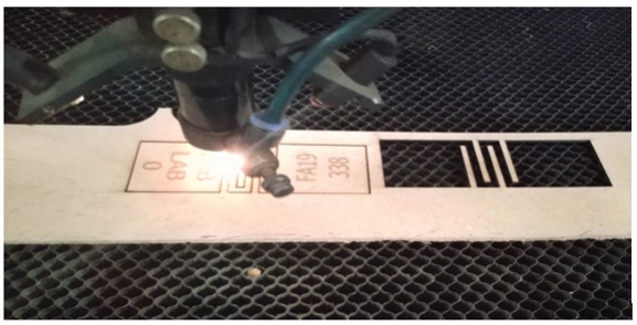
As I wanted to explore further, I have designed a Flexible Book Mark with FAB logo and My FAB Academy ID in MDF as seen below.
Design File –A4 Computer Controlled
Cutting_files\pf.rld
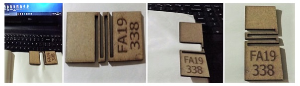 Issue –
 The FAB logo dint get engraved.
Solution - Then I made the required correction. Since the image was not getting engraved, I have replaced the design with FAB LAB 0.
Design File – A4 Computer Controlled
Cutting_files\pd.stl
This is how my bookmark looks after remodeling.
Learning OutcomeThis assignment helped me to learn about the Parametric Design and Vinyl Cutting along with screen printing. I have realized that in Vinyl Cutting, the sheet mode works better than the roll mode. Hence I stuck to the Pen Force to cut my design. During the Screen Printing Process, I understood that the best way is to use the pressure and fabric paint to get the print right.
The Press-fit design tools I’m familiar with, with a very basic interface, which I can now work with are Fusion 360 and Auto Desk. The Group Assignment taught me how to calculate the Kerf and the machine tolerance. We have also laser cut a lot of test parts in Cardboard, MDF and Acrylic with different Speed and Power inputs by learning how to manipulate the machine parameters to achieve the desired result. It was a good experience indeed, which I haven’t tried before.
Reference – FAB Academy tutorials.
https://www.instructables.com/id/How-to-Use-a-Laser-Cutter/