Group Project:
U Try to make something Big
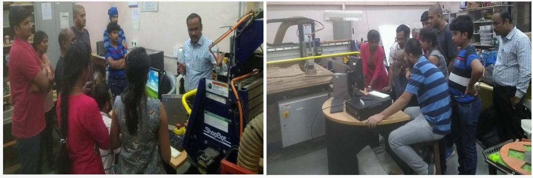
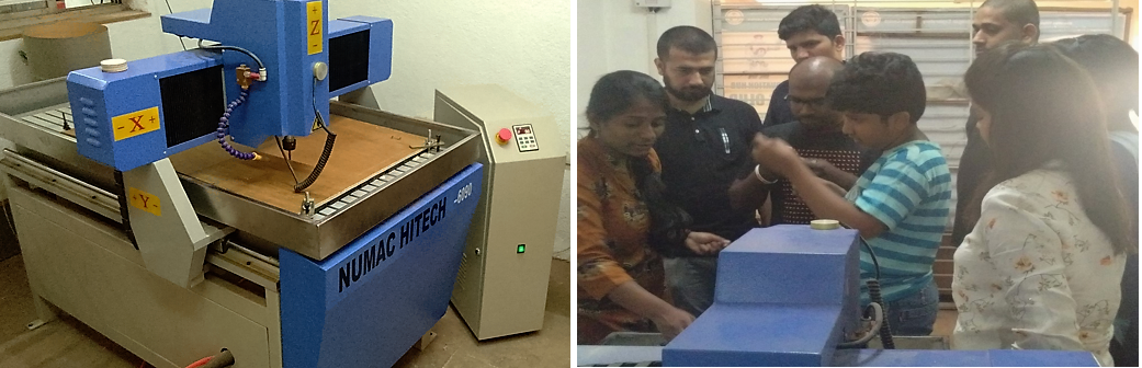
After Prof. Neil’s Global Class on Wednesday, our Lab Manager took our
Team to COPE, Pune on Thursday to take a tour of the Labs in the
campus, as we don’t have such big machines in our lab. The Instructor
has walked us through the Part Works and demonstrated the simple
cutting. We stayed overnight in the JP Naik Center, Kothrud Guest
House and visited Muktangan Maker Space. Then we came back to our lab
the next day.
Design Conception –
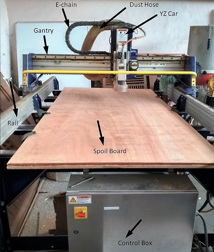
A ShopBot is a computer controlled 3 axis machine that can be
programmed to cut and carve a variety of materials. The ShopBot is an
incredibly useful tool for cutting complex shapes in sheet materials,
creating precisely fitted joints, making multiples of the same part,
and more. This is a safety and basic use class suitable for shop users
of all levels of experience and is a good starting point to gain
experience in CNC machining. Wood Shop experience and the CAD and CAM
Class are recommended as prerequisites for this tool.
ShopBot manufactures CNC tools that inspire people to turn their ideas
into something tangible. When we see our tools to work in innovative
ways, it reaffirms our commitment to the mission of making digital
fabrication technology readily accessible and usable for everyone.
ShopBot Tools began in the workshop/barn of Ted Hall more than 18
years ago. A professor of neuroscience at Duke University, In Ted’s
spare time, he wanted to build plywood boats and he was becoming
frustrated by the amount of time it was taking to cut the panels for
curved hulls with hand power tools. He thought one of the computerized
cutting tool called a CNC router would be helpful. So he started
thinking about a practical way to make one of the tools less expensive
more accessible - after all, they seemed to be just large plotters
that moved a cutter instead of a pen.
ShopBot founder Ted Hall created the company to make the power and
precision of digital technology available to and affordable for
individual "makers" and small to midsize manufacturers. Rather than
having to invest $100K or more to use CNC technology, a ShopBot
enables the use of digital fabrication with an investment of as little
as $5000.
ShopBot is the leading innovator in affordable digital fabrication.
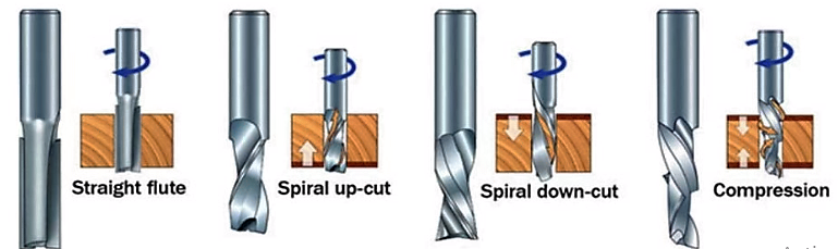
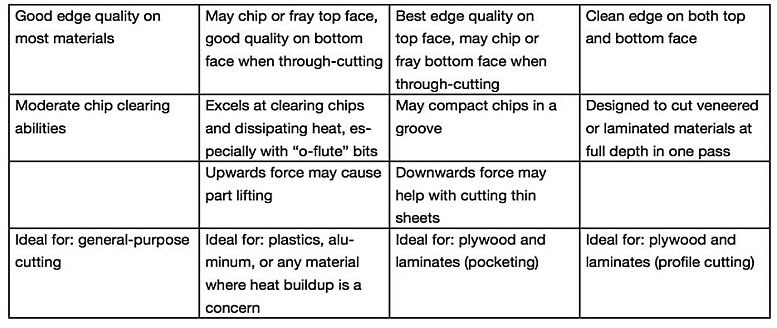
The different types of flutes are shown below.
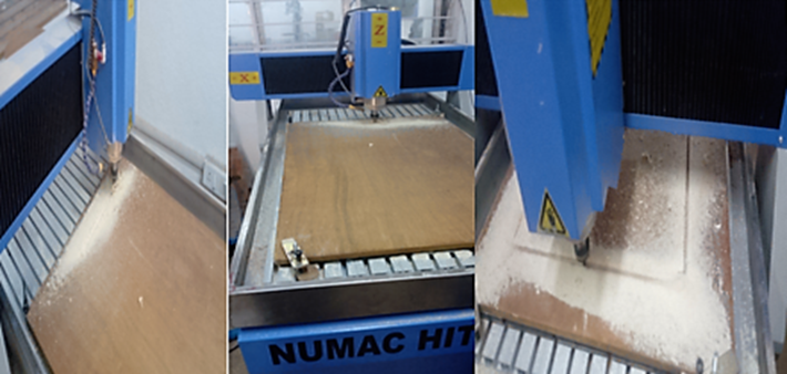
At Muktangan – Makerspace we saw this machine and the Lab Instructor
showed us a demo. She explained us about the following -
- Plunge rate - It is also known as stepdown, it is the distance in
the z direction per pass that a cutting tool is plunged into the
material.
- Spindle Speed - rotational speed of the cutting tool in
revolutions per min.
- Step Over - the maximum distance in the x/y direction that a
cutting tool will engage with uncut material.
- Feed Rate - Surface speed at the center of the rotating tool.
We cut different Objects. Then we varied the parameters of the cut for
each of the parts.
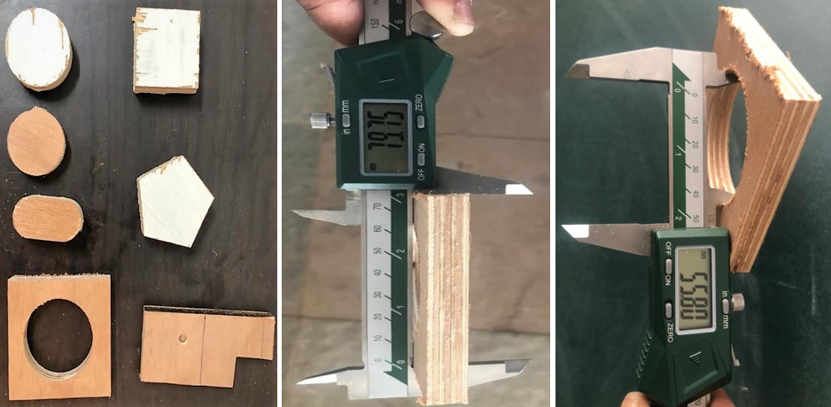
It has been observed that all these parts have cut on same speed and
feed rate. As we can see some kerf, I noted this important point. While
cutting our design we also learned how to change the milling bit. We
took a rectangle with 80mm X 80mm.after cutting we got a kerf 0.25mm.
Then we also cut circle in rectangular shape with 60mm diameter. We got
kerf of is 4.2mm both part cuts in the inner diameter. As seen in the
circle, we got a big huge difference in the kerf.
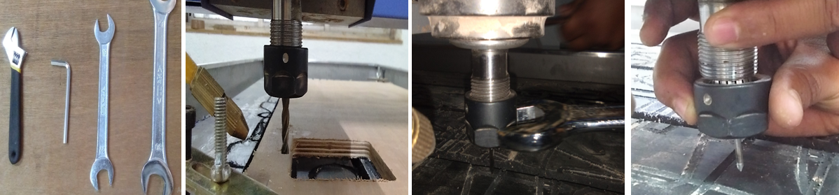
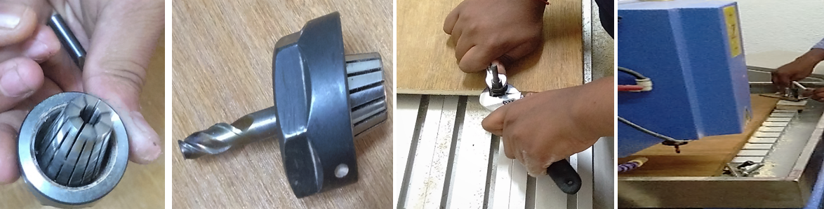
Tool Alignment There are two main parts in tool assembly:
a. Collet
b. Shank and the nut that tightens the collet.
Individual Assignment – Make something of your choice using the CNC.
After coming back from the COPE visit, I made my design ready the next
day, after proper understanding of the process on Monday, I went along
with my Team Mate Ms. Pooja J to Muktangan, Pune to finish my assignment
two days later. I understood that the Computer Numerically Controlled
Machine uses a cutting bit to shape up the object by cutting the
material at a high speed into your desired custom made design.
I have used Fusion 360 to design a simple press fit stool for my fab lab
on a SHOPBOT.
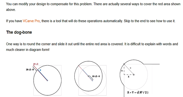
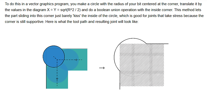
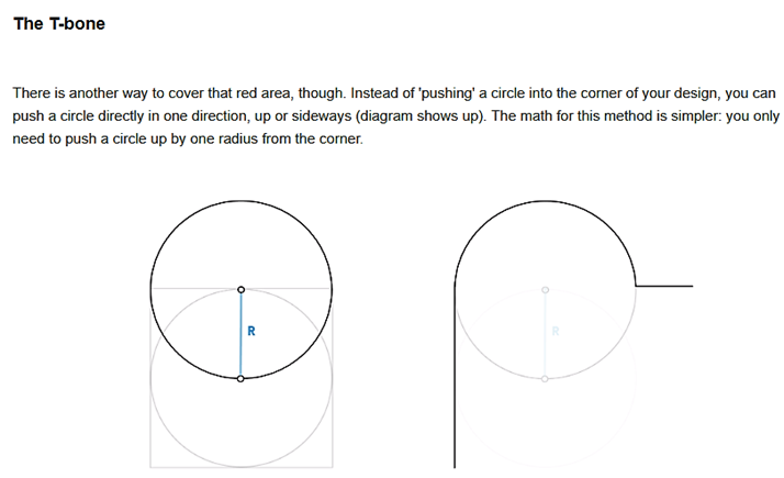
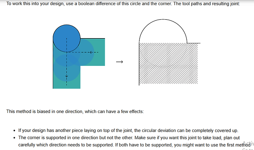
I’ve researched about the DOGBONE – The inside corner problem through
http://blog.inventables.com/2014/06/learn-about-milling-inside-corner.html
Fixing the inside corner problem –
Pocketing or Pocket Milling within the 2D or 2.5 Axis CNC part programming world. Pocket milling allows the machinist to use an end mill type cutting tool and machine away large amounts of material in a Roughing cycle prior to finishing the part. This saves time and efficiently maximizes the amount of material removal. Pocketing is for creating pockets, or pits in other words, into the material. One can create things like boxes or cups by using this strategy. Peripheral pocket or contour milling in wood machining, using flat end milling tool, can be performed with different tool paths. Technology designers of multi axis CNC wood machining use their experience and intuition to choose some of the options offered by CAM systems that determine the final shape of tool path, thus the generated tool path largely depend on individual judgment.
https://www.kth.se/polopoly_fs/1.686422.1550155780!/Student%20CNC%20Guide%20v0.4.pdf
Minimum cutting force, maximum dynamic stability of the process and minimum tool wear are achieved, or some other technological requirements are met, by using optimal tool path. Tool path optimization is based on analysis of possible tool paths and determination of cutting parameters which are dependable of chosen tool path and are affecting the main wood processing factors. Axial and radial depth of cut, engagement angle, feed and feed rate profile are identified as key parameters dependable of tool path, and their values and variations along the tool path influence the cutting speed, tool wear and cutting force. Knowledge of values and changes of those key machining parameters along the tool path is necessary for simulation and monitoring of the main cutting factors during the wood machining process.
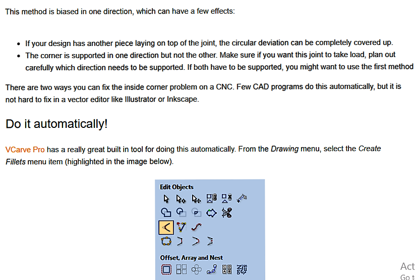
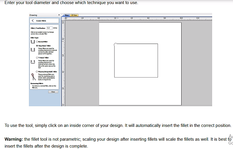
 https://www.vectric.com/products/vcarve-pro
CNC-Based Nesting Nested-based machining typically involves placing a single sheet of material on a CNC router table. The router is programmed to process components based on the machine's capabilities, in a single setup without any material handling required, other than loading and unloading. Nesting refers to the process of laying out cutting patterns to minimize the raw material waste. Examples include manufacturing parts from flat raw material such as sheet metal.
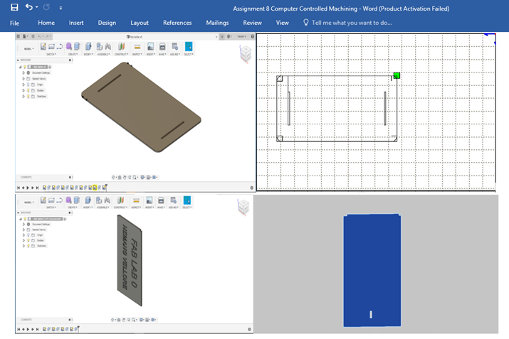
 My Design file looks like this –
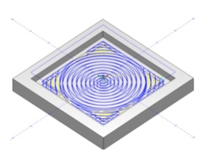
PICTURE OF THE SCHEMATIC
 Decoupage –
 The .DXT format saved which I saved was
later imported to the CNC software reading the 2D file as shown.
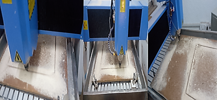
I have set the CNC manually to the 3 axis – X, Y & Z. The machine then starts cutting and engraving the when I set the point as 0 at the point where I want to objectify my design. As we do not have the Numac Hit Machine in our Lab,
I went to Muktangan in Pune for completing this assignment.
Due to the long queue of the Lab’s regular students, I had to rush up my given slot. Later I wanted to take the screen shots for documentation. Due to the power outage, I could not take screen shots of the process. I went back again after a month to take the screen shots, but the machine was on maintenance,
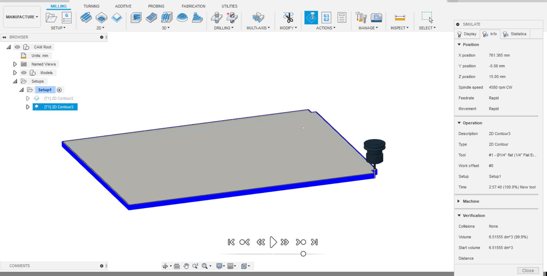
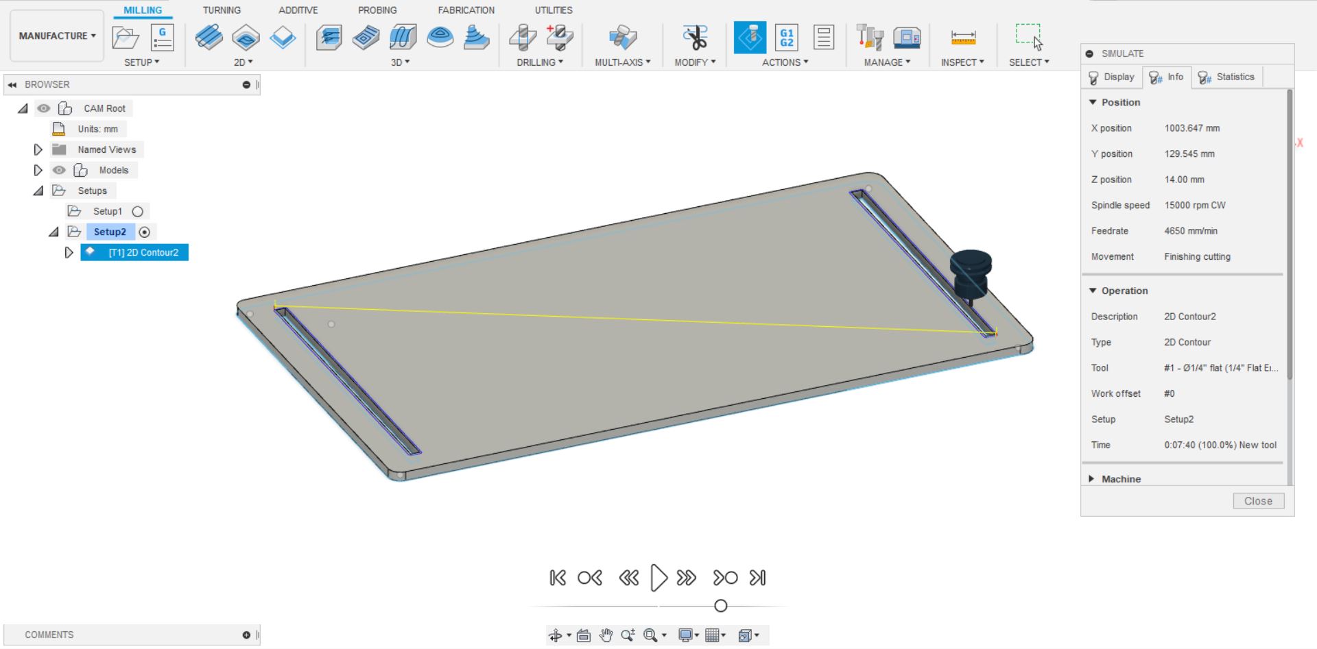
hence I tried to simulate the process in Auto Desk Fusion 360 to model my project and this is how its looks as shown below.
-Open cam module in fusion 360
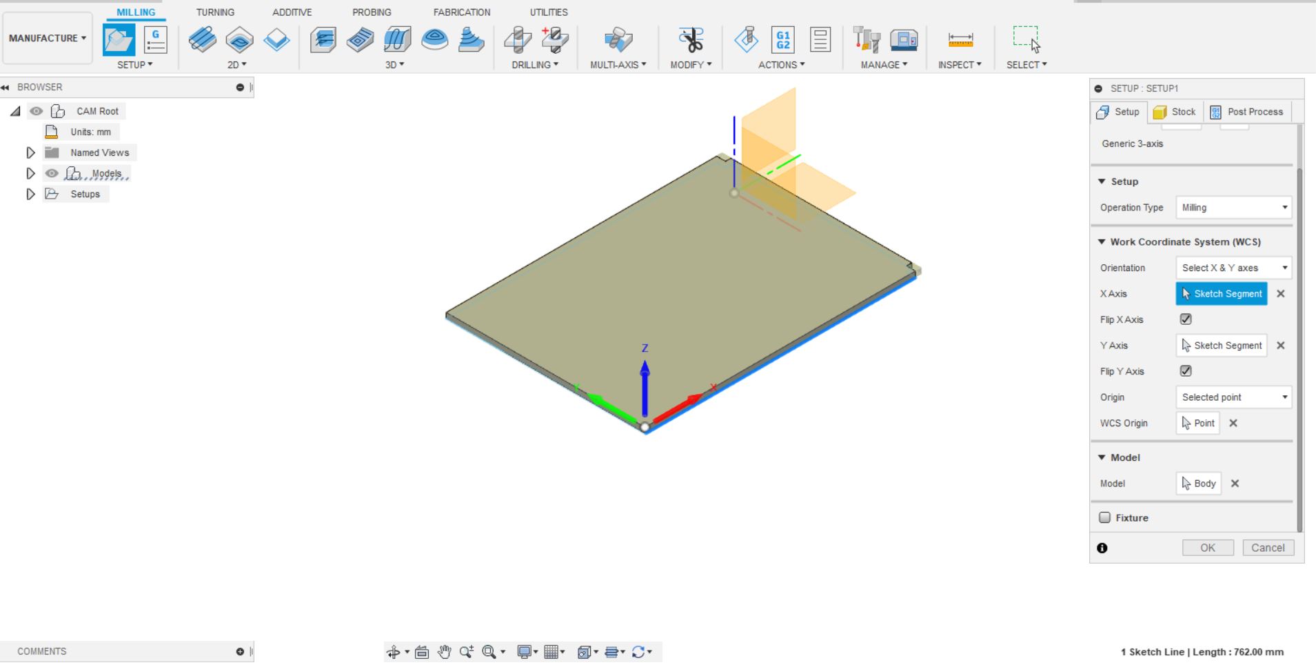
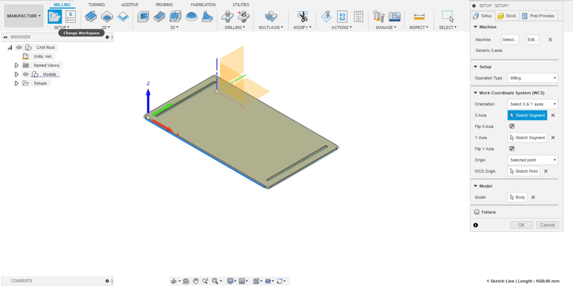
Now Select the body
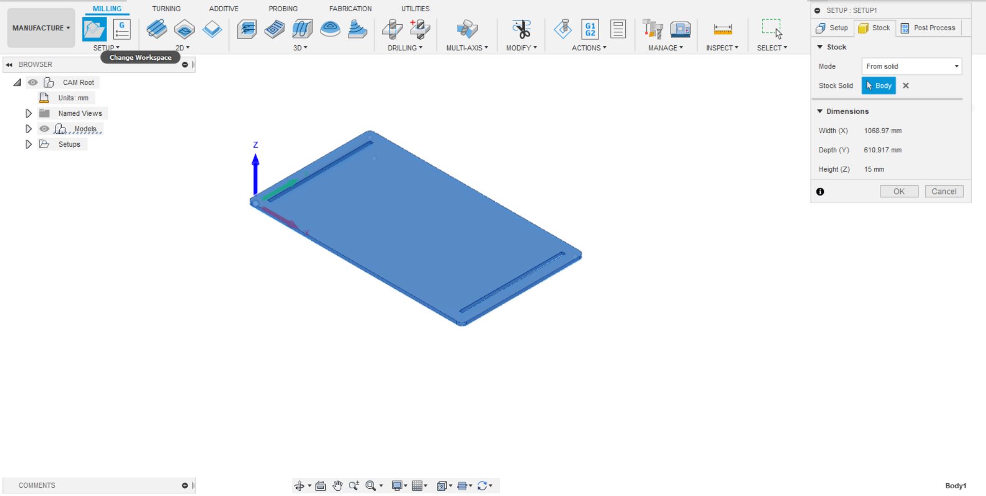
Go to stock
Mode: From Solid.
Stock solid: Select body
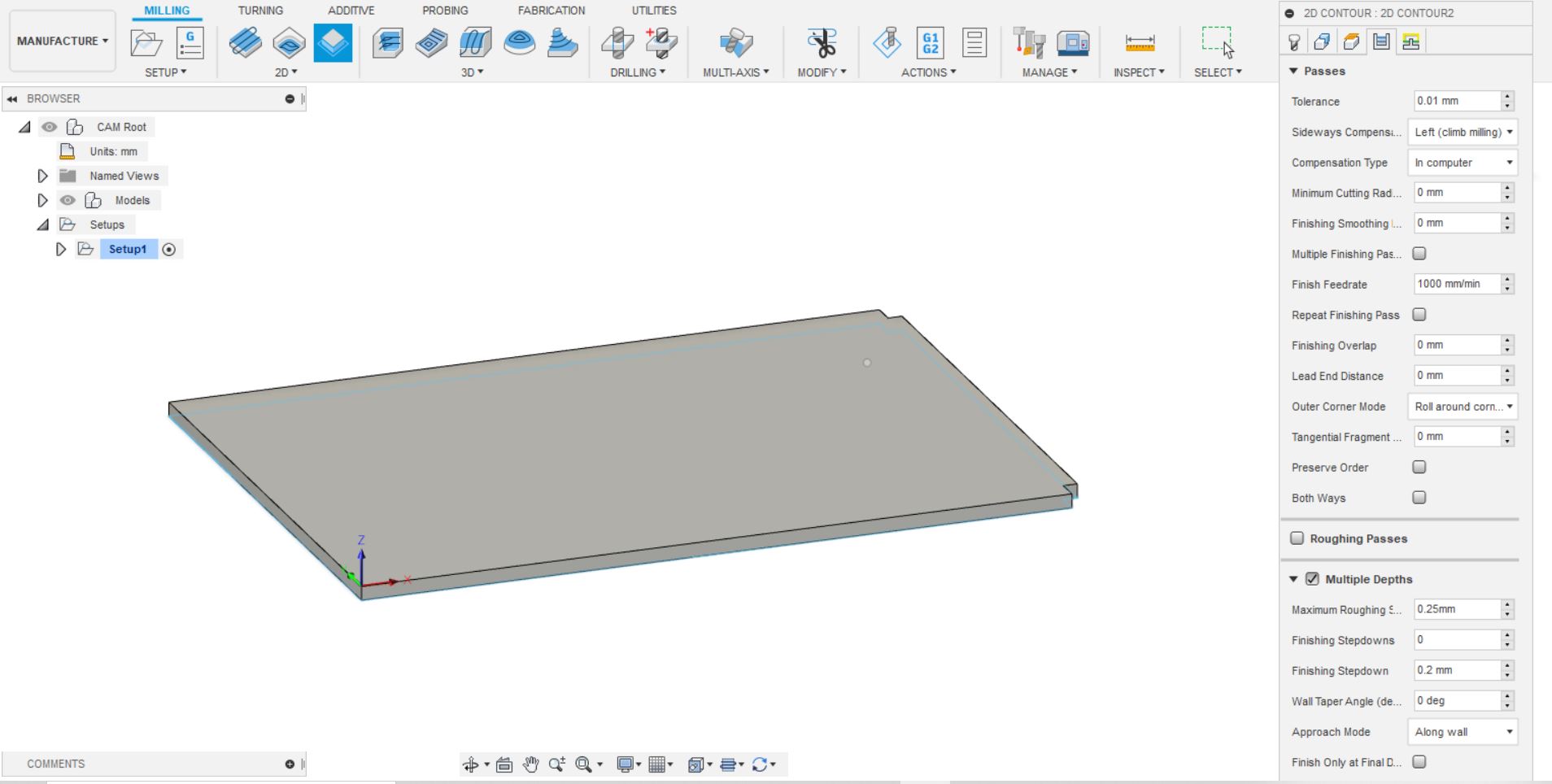
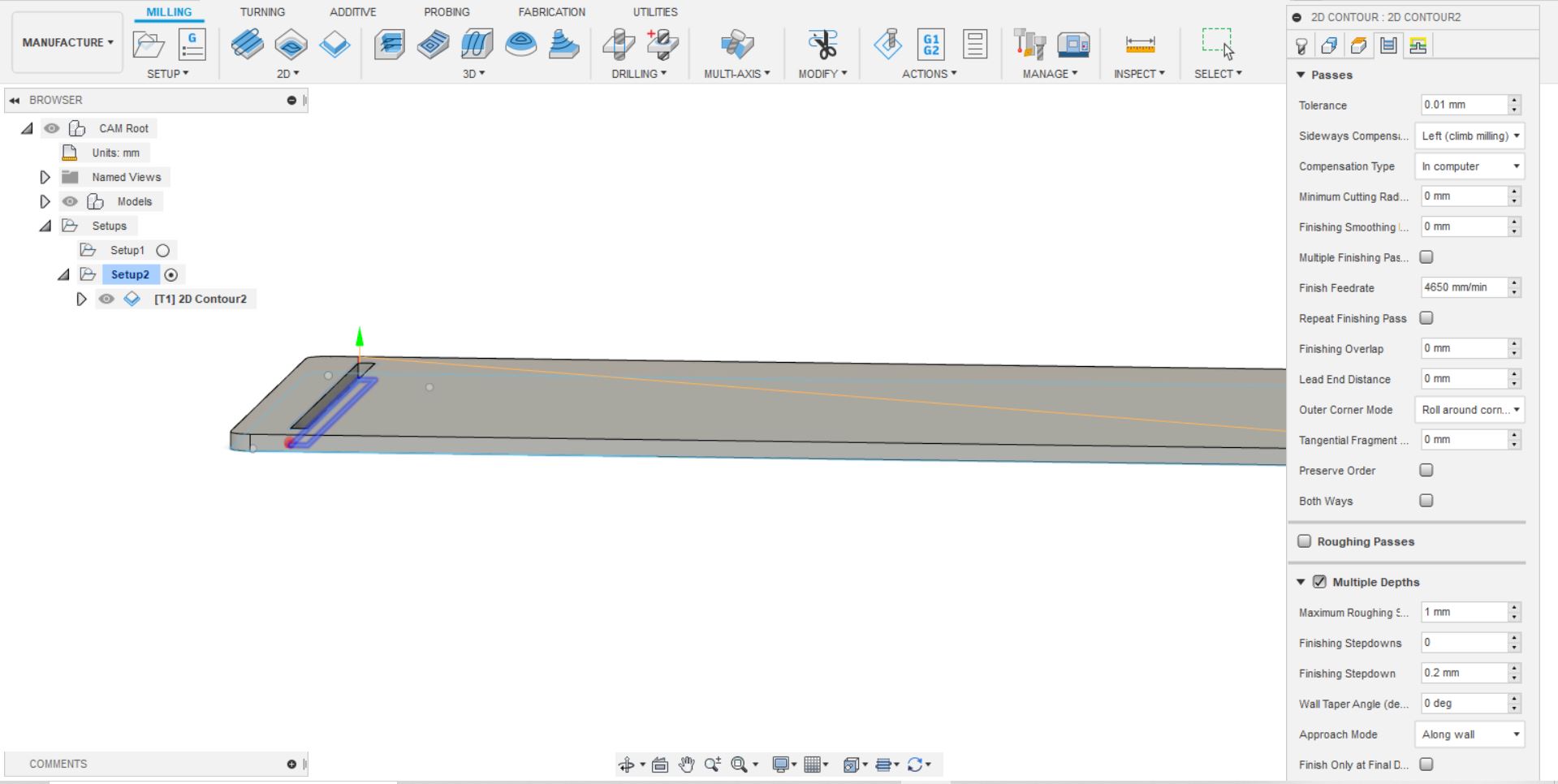
Click on 2D Counter
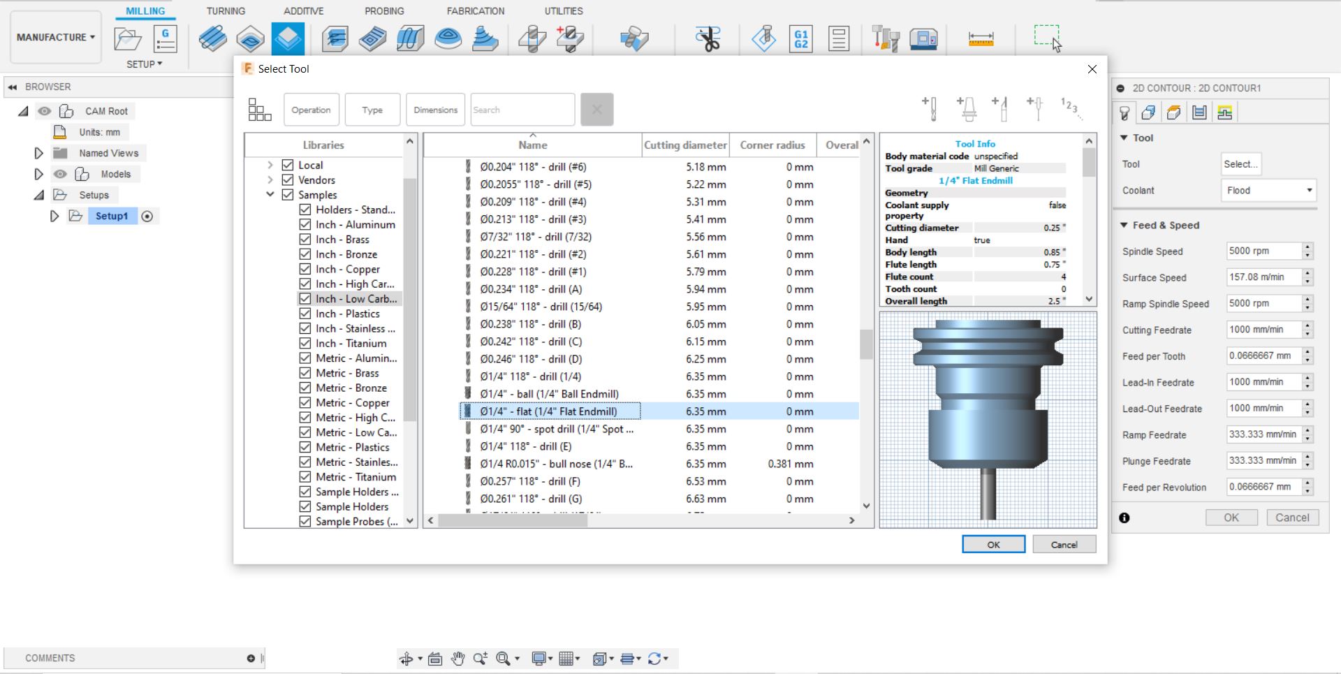
Tool: Select the required tool from the Tools Library (1/4” inch Flat End mill)
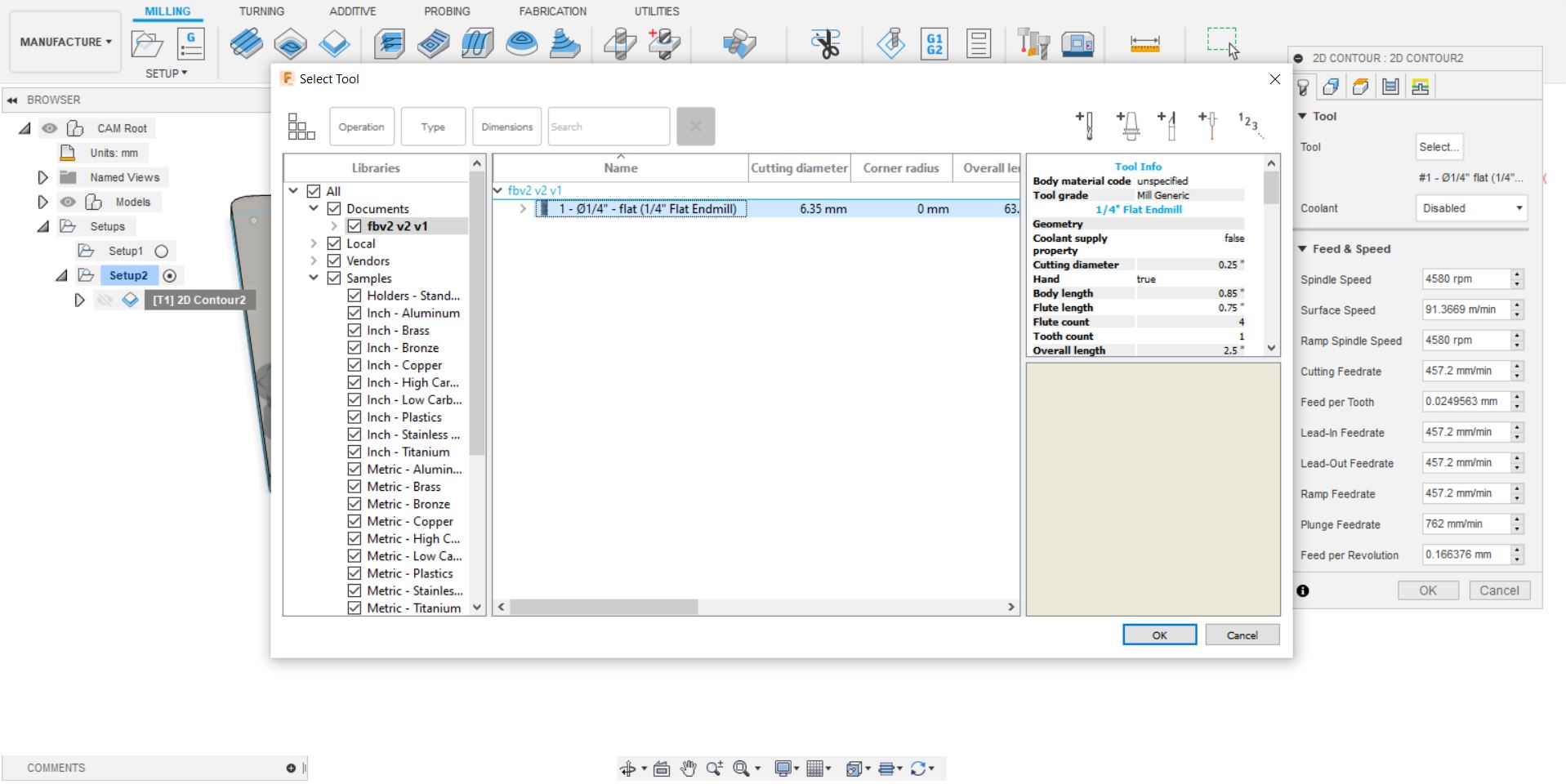
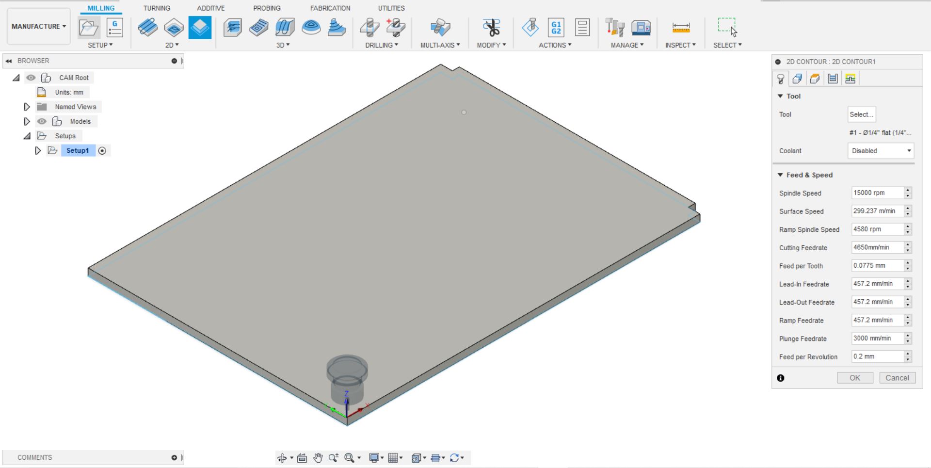
Coolant: Disable (Because the work material is wood)
Feed & Speed: A) Spindle speed: 15000rpm
B) Cutting Feed Rate: 4650mm/min
c) Plunger Feed rate: 3000mm/min
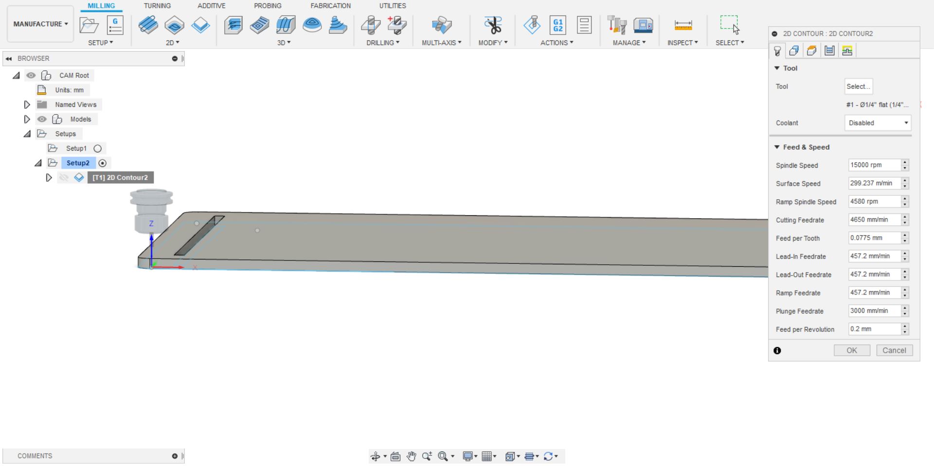
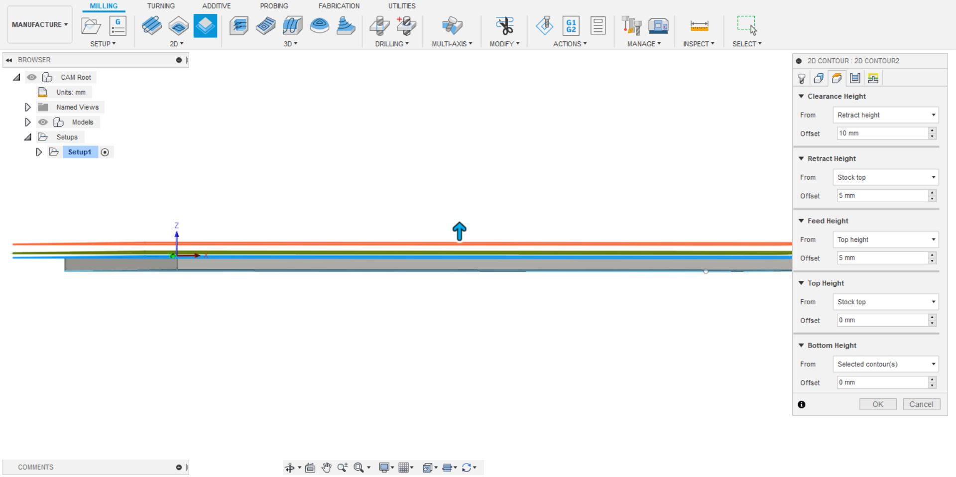
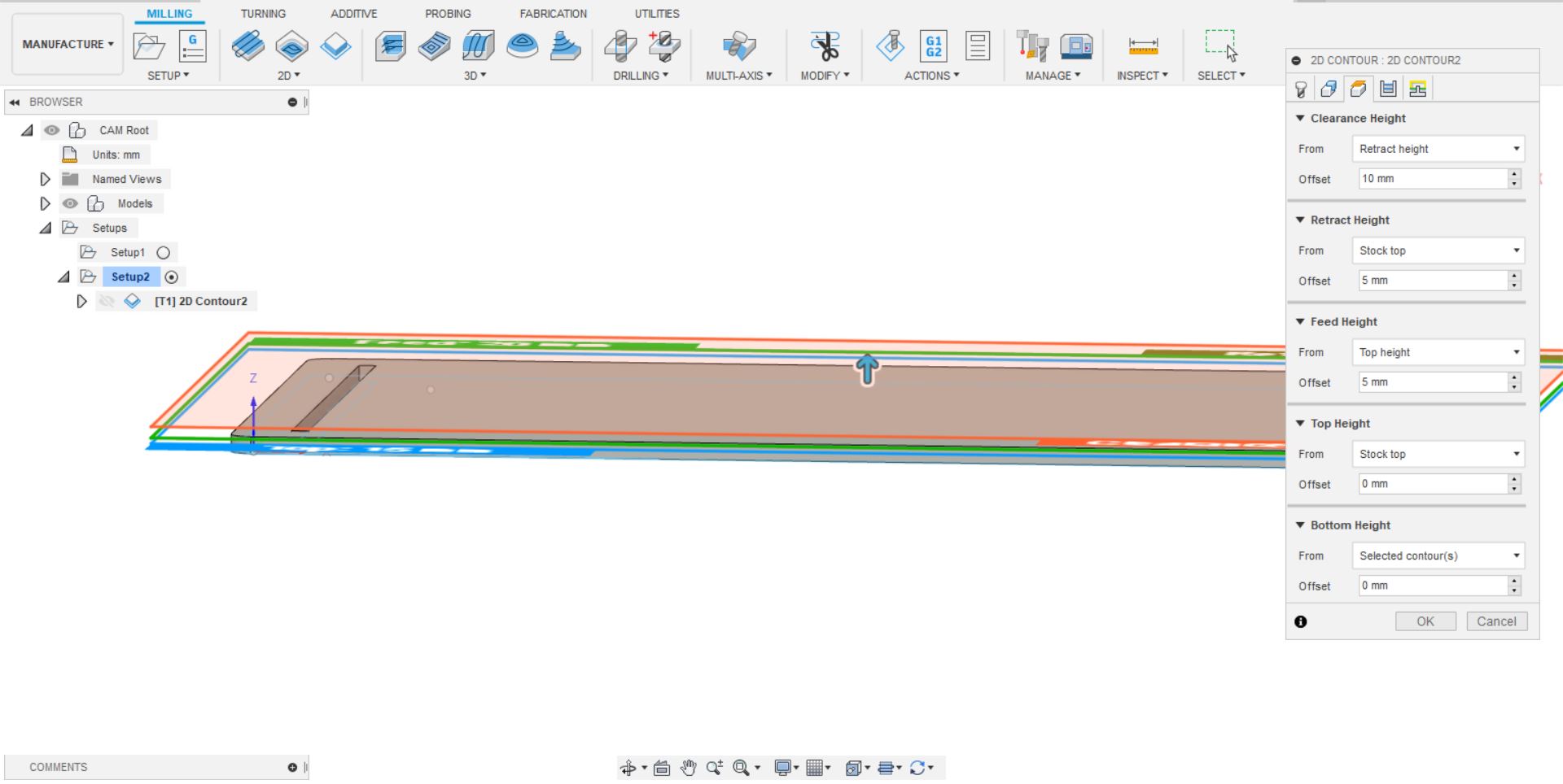
Tolerances and Safety Measures: A) Clearances height: 10 mm
B) Retraction height: 5 mm
C) Feed height: 5 mm
D) Top height: 0 mm
E) Bottom height: 0 mm
Select multiple passes: maximum roughing surface: 0.25 mm (Depth of cut in each pass)
Right click on the setup and simulate. (Preview of the machining process and shows the tool path)
Click on post processing, in post config select the type of machine software used so that it
converts according to its file extension format (Shopbot ISO).
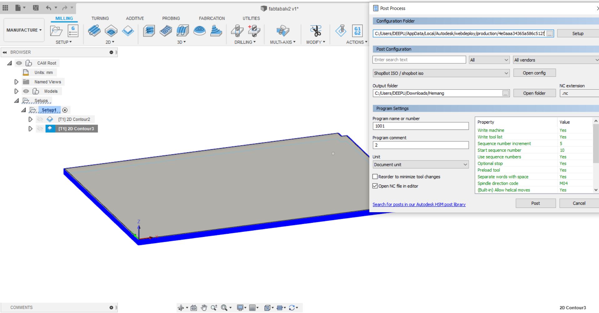
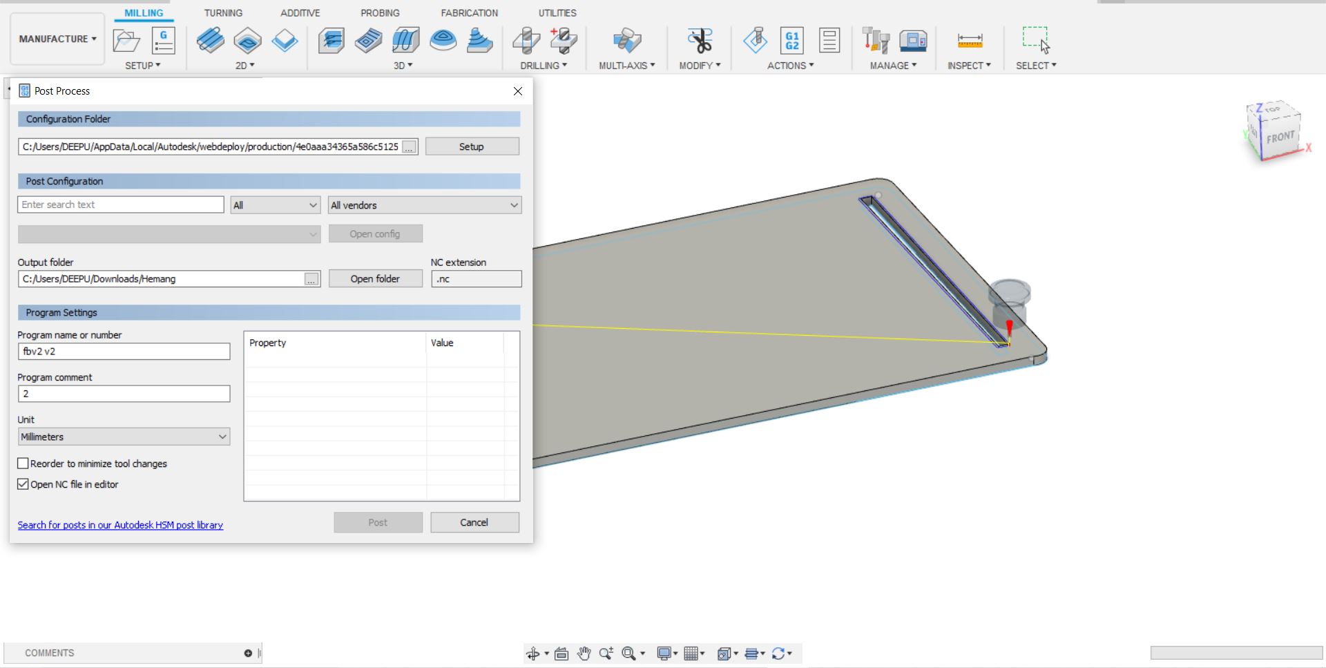
Program setting: Change the Program Name and save the file in required drive.
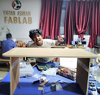
Hero Shot of My Design and Creation
I left my custom made press fit stool in Muktangan, which was later
brought to the lab after two months, along with the other objects made
by our Team in Pune. I enjoyed making this utility model for the lab.
Learning Outcome – I have understood that the design
changes as per the thickness of the material used in according to the
size of my custom made Multipurpose Stool. I enjoyed this assignment as
I was able to create my first design without any issues. Now my
multipurpose stool is a big hit in the lab. Glad that I made this
utility model.
References – FAB Academy Tutorials
https://www.instructables.com/class/ShopBot-CNC-Router-Class/
https://www.shopbottools.com/
http://blog.inventables.com/2014/06/learn-about-milling-inside-corner.html
https://www.shopbottools.com/products/software