Use the test equipment in your lab to observe the
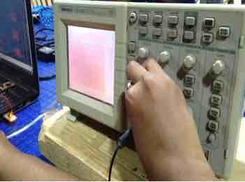
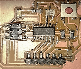
operation of a microcontroller circuit board.In this assignment we all are going to test our echo hello board with oscilloscope. We will monitoring how the voltage passes on the board and observe the voltage curve. Generally the good soldered board should give a rectangular wave. We performed a simple testing using DSO, (Digital Storage Oscilloscope). We tested the resonator on Jaydip's hello world board.
Digital Storage Oscilloscope is commonly used to display and analyze the waveform of electronic signals. The DSO is defined as “the oscilloscope which stores and analyzes the signal digitally”, i.e. in the form of 1 or 0 preferably storing them as analogue signals. It takes an input signal, stores the same and then displays it on the screen. The Oscilloscopes are used to observe the change of an electrical signal over the time. With the help of the oscilloscope we are now testing hello world board of Jaydip.
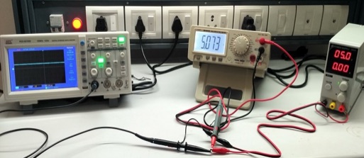
The Measuring probes are used for DSO and DMM respectively.
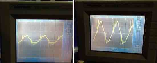
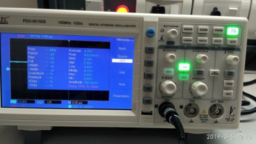
The Voltage wave form across Oscillator: Observing the voltage wave form across on 'hello world board' oscillator. Good soldering should give rectangular wave, but the board had wavy lines instead. It could be because of some problem in soldering.
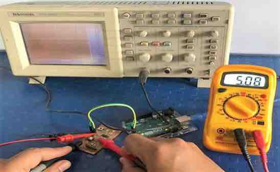
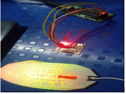
To know the Voltage, we connected the board with Ground and VCC supply and observed 5V reading on the oscilloscope. We confirmed it by observing the same value on Multimeter also as shown in the picture above. Finally we have understood that the DSO Oscilloscope is used for checking the wave behavior of the components. In this test, we have understood about the Oscilloscope’s parameters like Channels, Auto set, Frequency and, different wave signals.
Individual Assignment:
Redraw the echo hello-world board. Add (at least) a button and LED (with current-limiting resistor), check the design rules, make it. (If you have time this week, test it). Extra credit – Simulate its operation. Render it. My Design Conception –
File>New>Project in the Menu Bar, Then
Redraw the echo hello-world board,
Add at least one Button and one LED with a current limiting resistor,
Check the design rules, Make It, Test It. Extra credit given to
simulate its operation.
I have used Eagle for my pcb design. A PCB or Printed Circuit Board is
a board that contains several electrical components that are connected
using conductive electrical tracks. A PCB provides physical support
for mounting the electronic components and also the electrical
connections between them. The three steps or procedures:
Designing schematic of the design.
Drawing the layout for the Printed Circuit Board (PCB) and
Making the board (there are different ways to do this).
The first two tasks i.e. schematic and circuit board layout are done
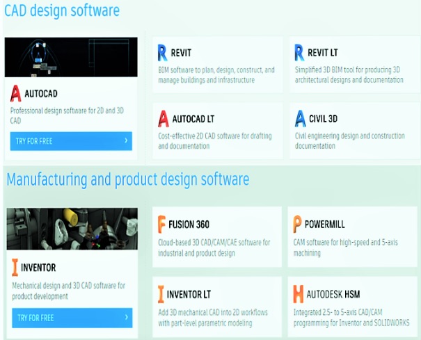
with the help of a CAD Tool. There are many CAD Tools for designing
PCBs like Altium Designer, Cadence or CAD, Mentor Graphics PADS,
KiCad, Autodesk Eagle etc.
Altium - Altium Designer is a PCB and electronic
design automation software package for printed circuit boards. It is
developed by Australian software company Altium Limited. It provides
a single unified application that incorporates all the technologies
and capabilities for complete electronic development. It integrates
board and FPGA level system design, embedded software development
and pcb layout, editing and manufacturing within a single design
environment.
CAD - Computer-aided design is the use of
computers to aid in the creation, modification, analysis, or
optimization of a design. CAD software is used to increase the
productivity of the designer, improve the quality of design, improve
communications through documentation, and to create a database for
manufacturing. Computer Aided Design software is used by
architects, engineers, drafters, artists, and others to create
precision drawings or technical illustrations. CAD software can
be used to create two-dimensional (2-D) drawings or
three-dimensional (3-D) models. There are
Building Designs
Infrastructure Designs
Manufacturing Designs
Product Designs
Mentor Graphics PADS – Mentor, a Siemens Business
is a US-based electronic design automation multinational corporation
for electrical engineering and electronics. The company was founded
in 1981 and sold to Siemens in 2017. Mentor Graphics Corporation is
a world leader in Electronic Design Automation (EDA) Tools business,
having annual sales of about $800 Million. It is headquartered in
the USA and is listed in NASDAQ (MENT).
KiCAD – KiCad is a free software suite for
electronic design automation. It facilitates the design of
schematics for electronic circuits and their conversion to PCB
designs. KiCad was originally developed by Jean-Pierre Charras. It
features an integrated environment for schematic capture and PCB
layout design. The features are as follows –
Schematic Capture - With the schematic editor you can create
your design without limit; there are no paywalls to unlock
features. An official library for schematic symbols and a
built-in schematic symbol editor help you get started quickly
with your designs.
PCB Layout -Make professional PCB layouts with up to 32 copper
layers. KiCad now has a push and shove router which is capable
of routing differential pairs and interactively tuning trace
lengths.
3D Viewer - KiCad includes a 3D viewer which you can use to
inspect your design in an interactive canvas. You can rotate and
pan around to inspect details that are difficult to inspect on a
2D view. Multiple rendering options allow you to modify the
aesthetic appearance of the board or to hide and show features
for easier inspection.
I have used Autodesk Eagle for designing my PCB as I have found it
very convenient.
Eagle - Easily Applicable Graphical Layout Editor
can run on any operating systems like windows, Mac and on Linux.
Make anything with EAGLE PCB design software. Autodesk EAGLE is an
electronic design automation (EDA) software. Enabling printed
circuit board (PCB) designers to seamlessly connect schematic
diagrams, component placement, PCB routing and comprehensive library
content. Also it requires less memory space anywhere from 50-200MB
of disk space. It’s free/low cost software or you can download
educational license for 3 years free. It has best community support
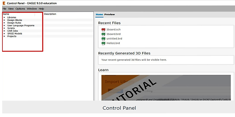
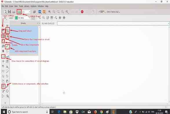
and more. I was exploring the Control Panel of Eagle. The first time
you open up Eagle, you can see this view.
You can explore the six separate trees in the control panel, which
highlight separate functions of the software:
Libraries - Libraries store parts, which are a combination of
schematic symbol and PCB footprint.
Libraries usually contain a group of related parts, e.g. the
atmel.lbr stores a good amount of Atmel AVR devices, while the
74xx-us.lbr library has just about every TTL 74xx series IC there
is.
Design Rules (DRU) - Design rules are a set of rules your board
design must meet before you can send it off to the fab house. In
this tree you'll find DRU files, which are a pre-defined set of
rules.
User Language Programs (ULPs) - ULPs are scripts written in EAGLE's
User Language. They can be used to automate processes like
generating bill of materials (bom.ulp), or importing a graphic
(import-bmp.ulp).
Scripts (SCR) - Script files can be used to customize the EAGLE user
interface. In one click you can set the color scheme and assign key
bindings.
CAM Jobs (CAM) - CAM jobs can be opened up by the CAM processor to
aid in the creation of gerber files.
Projects -- This is where each of your projects gets organized into
a single project folder. Projects will include schematic, board
design, and possibly gerber files. (Source internet)
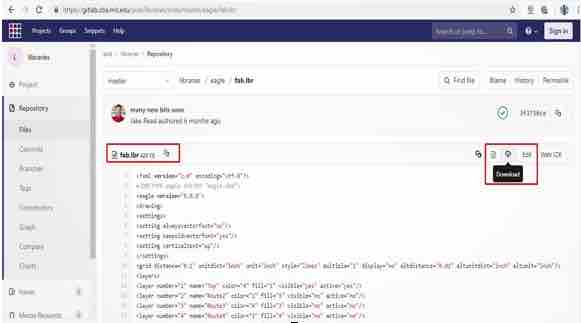
After downloading the Eagle and overviewing the control panel the
imp part is "add the library", for our Echo board we are using by
default given library called fab.lbr
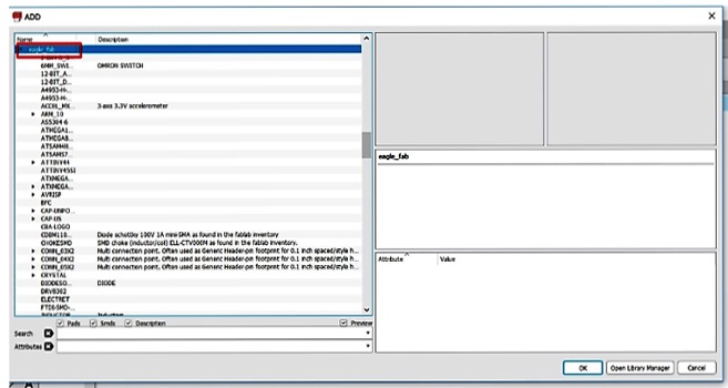
We can download any fab.lbr to your laptop. Open ADD Menu with
EDIT>ADD
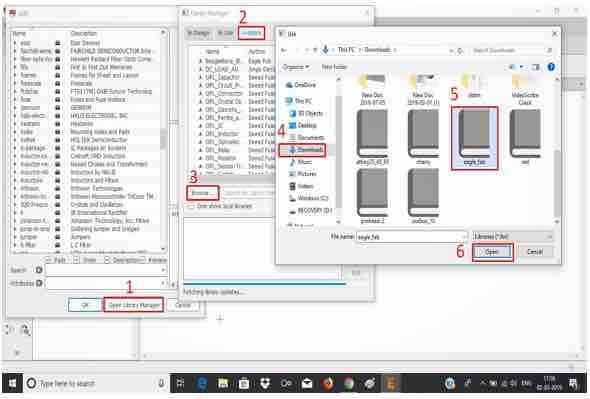
If the Fab Library is not in the list, then open the Library
Manager. Browse for fab.lbr and close the prompt.
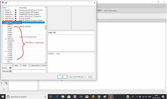
Now you can see the Fab Library in the list on your laptop as shown
below.
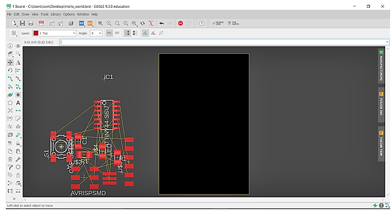
I have download the Auto Desk Eagle Student Version. This is control panel of Eagle. There are various control parameters like Libraries, Design rules, Projects, Examples etc.
This is the user interface for Auto Desk Eagle.
I have added a New Project by adding the component.
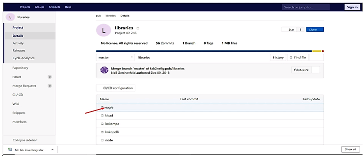
I noticed that we can also add Auto Desk Eagle version from the fab.lbr
I have downloaded fab.lbr from git hub.
The installation procedure and fab.lbr components can be seen in the picture above. Designing
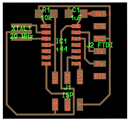
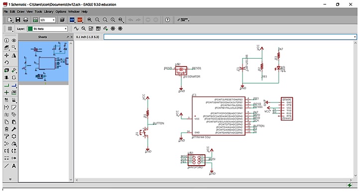
It’s now time to Design the My Circuit. After going through Prof.
Neil’s design repository, I have identified the appropriate
components and their connection to the rest. Then added a Push
Button, an LED and a Resistor to my circuit.
It’s time to make my pcb, so Inow I have to design it in Schematic
Eagle.
I have followed the procedure shown in the picture above.
Initially I have calculated the Resistor Value to be added.
For this purpose, I have used the OHM’s Law. V=IR→ R=V/I
Voltage= Current× Resistance. V= I×R. V= voltage, I= current and R=
resistance.
The SI unit of resistance is ohms and is denoted by Ω
This law is one of the most basic laws of
electricity.
Ohm's Law formulas V = IR, I = V/R, and R= V/I.
Voltage (Operation): 1.8v red, 2.1v green, Current Max: 10mA
It’s not necessary to get constant full brightness. Can operate at
~30%. Input Voltage of V-5V, then R=5V/0/10mA=500Ω
The Components used are:
supply1/+5V
supply1/gnd
fab/attiny44-ssu
fab/resonator
fab/res-us1206fab
fab/cap-unpolarisedfab
fab/avrispsmd
fab/ftdi-smd-header Enhancement:
Fab/6mm_switch6mm_switch
Lad/ledsmt1206
After calculation of resistor value, started with the actual
Schematic Design.
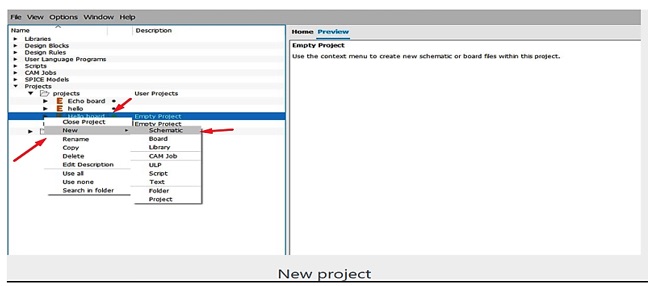
To Create a new project from the Control Panel, in the Project
created a new schematic and named it. Later opened it in the
schematc window.
Right Click on the newly created project. Select New>Schematic as
shown below.
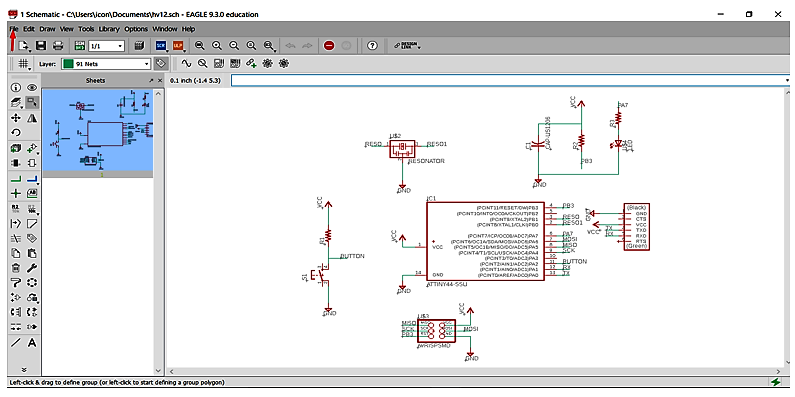
The Design is divided into two main parts –
The Schematic and
The Proprietary Board => Board Layout.
Find the components with the Add Platform Function label each port
with the Label Function.
Use the Function Net for creating the links, Lastly ERC Function to
check for any errors.
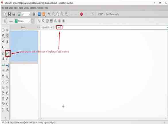
Edit>add prompts in the add menu. You may have to open the fab
lib, and look for the component you need click. And click OK.
VCC and GND are selected from supply1 lib
Place the component somewhere in the schematic. The component can
later be moved/rotated.
Pess ESC once you are done placing one component.
Connect the different components according to the given board to the
datasheets if needed.
Draw > Net to draw the connections between the components.
Give values to the components:
Rightclick a component to show menu
Value and insert the desired value.
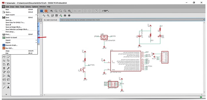
After the schematic, go to file.
Before Tracing, it’s advisable to do the design rule check.
Then Open the File and Switch to the Board part.
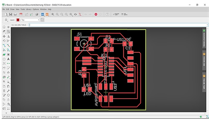
I have done it, Yeah!
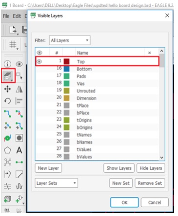
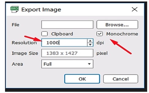
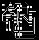
On keeping various layers on/off the details were added/removed. For engraving the file was exported keeping only the Top layer on, and for cutting keeping only dimension layer on.
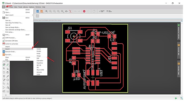
Time for Monochrome, Go to File and go to Export, Go to Image. The files are saved in .png format.
This is how the monochrome is rereceived
It’s done. Now this is how my Monochrome looks like.
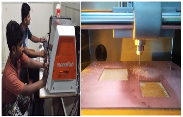
The machine SRM-20 cuts the Black portion and leaves the White colored design. It’s important to have the image in Black-White. Then I have adjusted the resolution to 1000 dpi. Now I am all set to mill my PCB as seen under. Using Fab modules (http://fabmodules.org/) I have converted the .png format files to .rml giving values of speed, x, y, z coordinates, name of machine, end mill size etc. I have used mono Fab SRM 20 milling machine using the end mill 1/64 for tracing and 1/32 for cutting and milled the PCB. I used the software V Panel to instruct the machine.
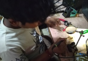
Then I have soldered the PCB. Soldering is a process in which two or more metal items are joined together by melting and then flowing a filler metal into the joint, the filler metal having a relatively low melting point. Soldering is used to form a permanent connection between electronic components.
Procedure I have followed before soldering my PCB -
1. I rubbed the surface of the freshly milled PCB board with a higher grit sandpaper.
2. Then cleaned the tip of the soldering iron.
3. I heated the soldering iron to 340° C prior to use.
4. I applied flux to the trace pads before soldering the PCB.
5. I used very little solder to one of the pads, which proved best.
6. By using the filler, flux and the soldering rod, I have placed and fixed all the components on the PCB.
My PCB after soldering looks like this. Huh, finally done.
Design File - Assignment 7 Electronics Design_files\Hello
echo.brd Testing of PCB using Multimeter and Oscilloscope –
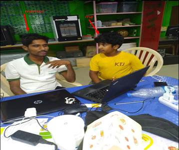
Jaydip and myself tested our boards in Muktangan.
Initially we tried with DSO (Digital Storage Oscilloscope), DMM (Digital Multimeter) and DC (Direct Current) power supply. We set DC power supply to 5V DC and checked the voltage on DMM and DSO, as shown below –
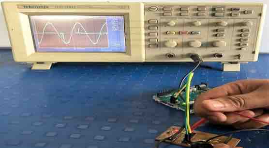
"DSO" Oscilloscope for checking the wave behavior of the components. In this test, the oscilloscope’s parameter are channels, auto set, frequency, different wave signals. The digital storage oscilloscope is defined as the oscilloscope which stores and analysis the signal digitally, in the form of 1 or 0 preferably storing them as analogue signals. The DSO takes an input signal, stores it and then display the same on the screen. We can see the behavior of any electronic component and also check the various parameters using DSO, as shown below –
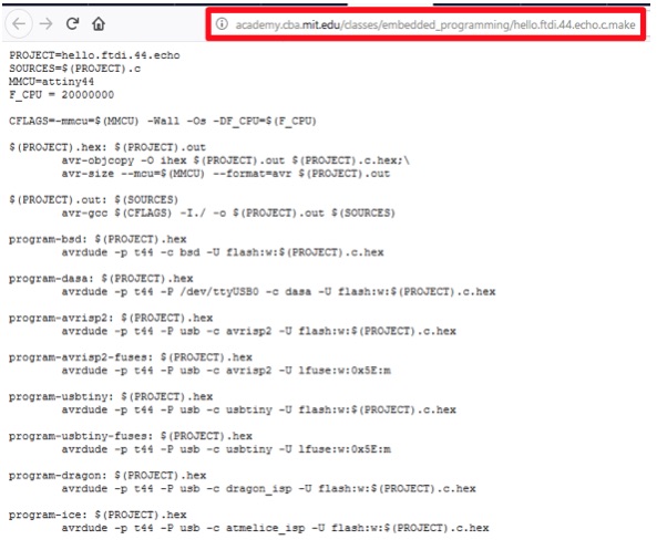
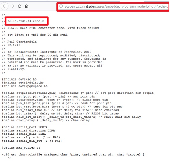
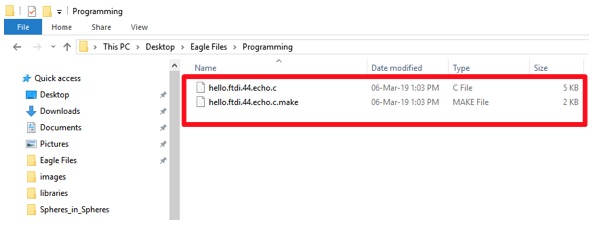
Saved “hello.ftdi.44.echo.c” and “hello.ftdi.44.echo.c.make” files in PC>Dekstop>Eagle files>Programming.
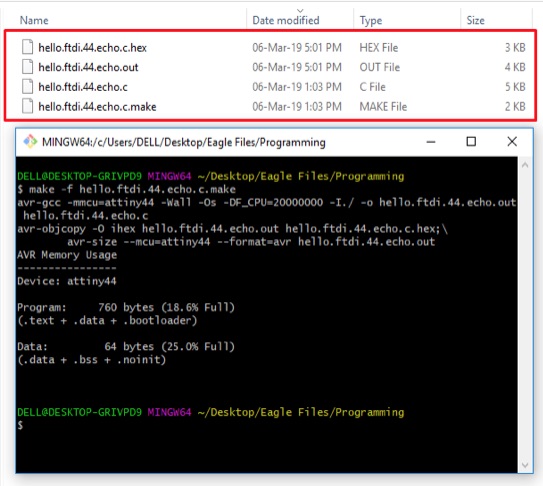
Hex File: 2 additional files HEX and OUT format were created in the same folder. This is basically the language in which the program will be written on the board.
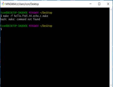
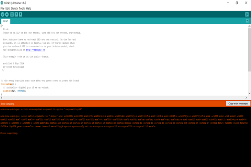
But the Programing guide did not work.
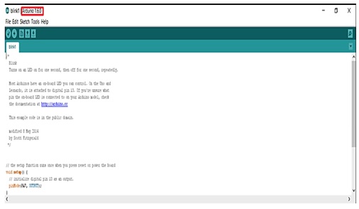
First we installed the wrong version. Later we installed 1.6.0
version and tired with Ardiuno IDE.
It did not work. So I hacked Arduino 1.6.0 version.
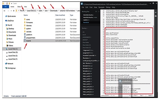
When hacked, it was ho ho; but hoy hoy, it had a problem. The
problem was ATTiny not working, as it was not detected.
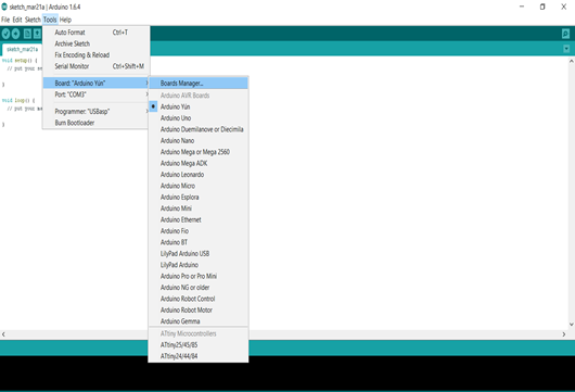
So we researched about adding attiny in ardunio and realized we have
to use 1.6.4 then it worked
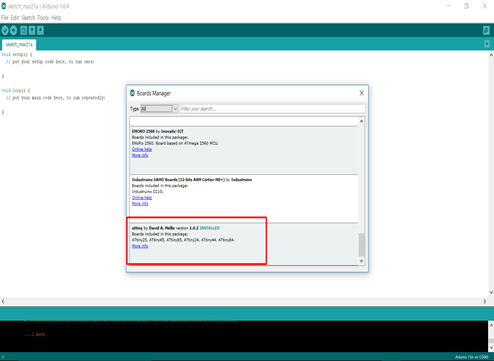
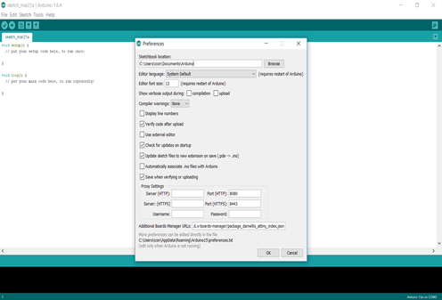
Then I installed ATTiny package and opened the broad manager. Posted
the URL for ATTiny and used 1.6.4
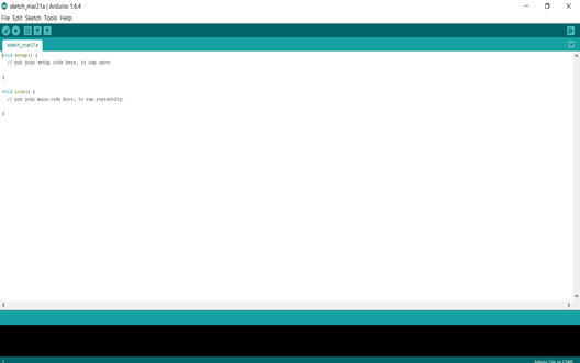
void setup() {
// initialize digital pin LED_BUILTIN as an output.
Int ledpin = PB3;
pinMode(ledPin, OUTPUT);
}
// the loop function runs over and over again forever
void loop() {
digitalWrite(ledPin, HIGH); // turn the LED on (HIGH is the voltage level)
delay(1000); // wait for a second
digitalWrite(ledpin, LOW); // turn the LED off by making the voltage LOW
delay(1000); // wait for a second
}
Finally it is working now. Ho Ho Done.
Learning Outcome:
I have learnt how to design by using eagle, create the schematic and
program the pcb using Arduino ide and route the board to make my own
pcb. Using the Multimeter to check the board connections and
Oscilloscope for basic testing. This is a huge learning and was
taking a toll on me. Always remember to check the continuity with
the board and go ahead on routing. But glad that could finish the
assignment without a glitch. See you in the next assignment. Bye!


