Group Assignment:
All the various programs running on the computer are
executed by its Processor. Based on the AVR processor there are also
the avr-gcc and avrdude as the compilation programs.
Embedded Programming:
A programming language can be used to develop and use an information
system. The most popular of them are C, C++, Java, PHP and Python. The
Processor is the heart of the embedded system. The knowledge of the
Microcontroller and Microprocessor are a must.
The essential Units are:
Control Unit - CU and Execution Unit - EU.
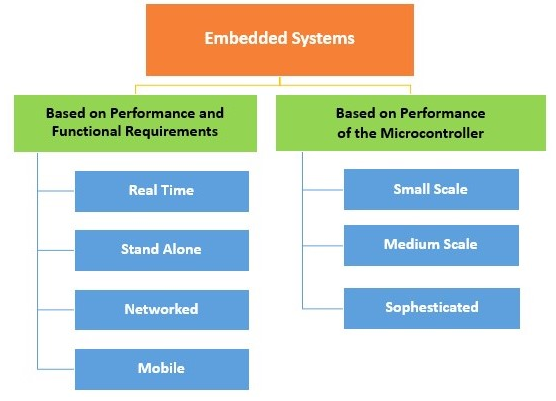
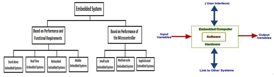
For the Group assignment, the goal was to compare performance and
development workflows for different architectures.
From the archive data, these are the five major Atmel Architectures that
are used during the Fab Academy.
ATtiny44
ATtiny45
ATtiny84
ATtiny85
ATMega328P
Programming Tools:
RTOS, Source Code Engineering Tool, Simulator, Debugger and IDE –
Integrated Development Environment.
Various Processors –
General Purpose Processors – GPP
Microprocessor
Microcontroller
Embedded Processor
Digital Signal Processor
2. Application Specific System Processor – ASSP
3. Multiprocessor System using GPPs.
Limitations - In a Medium Scale Embedded System there are a single or
few 16 or 32 bit Microcontrollers or Digital Signal Processors – DSP or
Reduced Instructions Set Computers – RISC. Both have Hardware and
Software complexity.
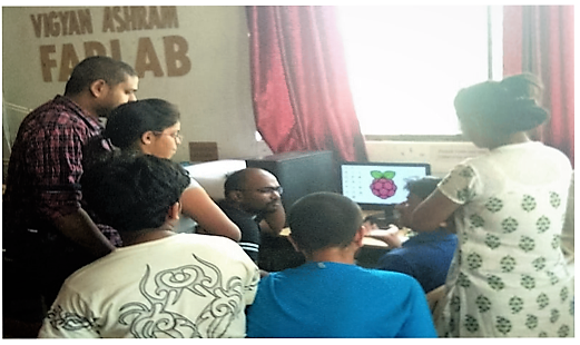
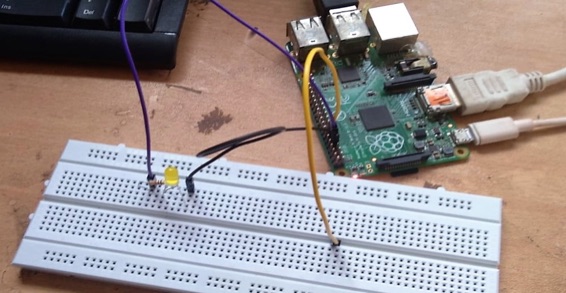
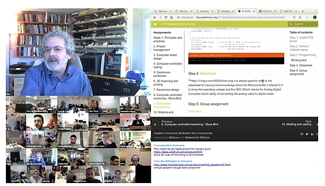
Task – In the Individual Assignment, I have used
Arduino IDE, so we tried Rasperry Pi. Our instructor walked us through
the basic concepts. I understand that it’s a processor with ARM
Processor IC and works like a PC’s CPU with some advance features like,
*can process multi task at a time
*has a simple editor
*can use python for program
*has an in built usb, ethernet, camera port for interfacing.
My team mate Manoj, took the lead in showing us the procedure as shown
below –
The python code used by writing a simple code in python to blink LEDS
with description.
import GPIO as g #importing the
general purpose input/output pin control library and renaming it as
'g'
import time #importing the time library
g.setmode(g.BCM) #setting the pin layout based on BCM rather than
normal numbering
g.setup(18 , g.out) #defining the output pin
print "led On" #Printing the LED ON in terminal
g.output(18 , g.HIGH) #Turning the output HIGH
time.sleep(1) #Sleeping for 1s
print "led Off" #Printing led off on screen
g.output(18 , g.LOW) #Turning the output LOW
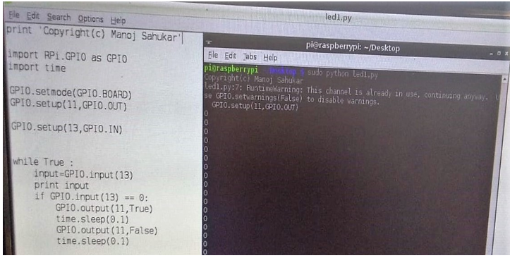
RaspberryPi Model-B Plus - Programing with Python - LED Blink with
Switch-
# Python Program
import RPi.GPIO as GPIO
import time
GPIO.setmode(GPIO.BOARD) # BOARD mode is recommended to make program
run on different RPi.
GPIO.setup(11,GPIO.OUT)
GPIO.setup(13,GPIO.IN)
while True :
input=GPIO.input(13)
print input
if GPIO.input(13) == 0:
GPIO.output(11,True
time.sleep(0.1)
GPIO.output(11,False)
time.sleep(0.1)
Testing Video -
https://youtu.be/tJE3Evde_sQ
Push Button Program
 My experience of using a different environment –
As known, an Arduino is a microcontroller motherboard 0.002MB memory. A
microcontroller is a simple computer that can run one program at a time,
over and over again. The Clock Speed-Arduino has 16 Mhz with an on board
network and it’s very easy to use. It’s pocket friendly to use.
USB-Arduino has one input only. It only provides a subset of the
functionality of the Raspberry Pi.
A Raspberry Pi is a general-purpose computer, usually with a Linux
operating system, and the ability to run multiple programs. I understood
that the Raspberry Pi is an independent computer with a memory
of 512 MB that can run an actual operating system in Linux. It is more
complicated to use than an Arduino. Raspberry Pi clock speed is 700Mhz
and has two inputs. So Raspberry Pi has maximum rate of execution of any
operation and a little expensive to use. Well, it might sound
like Raspberry Pi is superior to Arduino, Raspberry Pi it
has wired Ethernet network but that's only when it comes to software
applications.
I find that Arduino's simplicity makes it a much better bet
for pure hardware projects.
Individual Assignment – Program Hello Echo Board
Program my PCB to perform a task with various program languages and
different environment. Write the C code to my program, compile it to the
avr-gcc and send it to the microcontroller with avrdude.
When my program is good, learned to understand from the board as to How
to Modify and Create my own Makefile for my hello echo board. The
structure of the pattern can be seen below.
Name of the file to compile
* Extension of the file to compile
* Microcontroller to program
* Frequency of the board to program
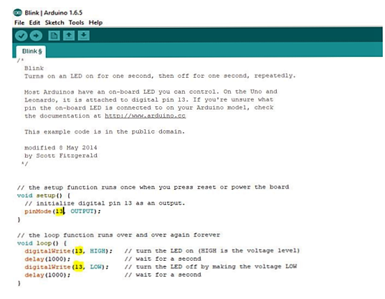
Program – Create a Circuit Code which turns on and off
the LED in a pattern.
Code in Action:
We can use the serial monitor in the Arduino IDE to enter a single
character and the hello echo program on your board will store the
character and then echo (repeat it back) to the serial monitor. The
program will store each character and repeat the series back to you each
time.
Using the Arduino IDE: Download the Arduino IDE from
www.arduino.cc
Step 1: Open Arduino and then enable the Serial
Monitor.
The serial monitor window will open.
Make sure the "115200 baud" setting is selected.
Step 2: Type a single character into the top text entry
area.
Press "send" or hit the key.
The character you type on the keyboard will be sent to the board via the
serial port on your computer.
The C code on the board will echo back the character that you typed.
Type another character into the top text entry area and hit "send" or
hit the key.
The characters you have typed so far are stored and echoed back along
with the new character that you typed.
Keep typing characters and letting them echo back until you reach the
limit.
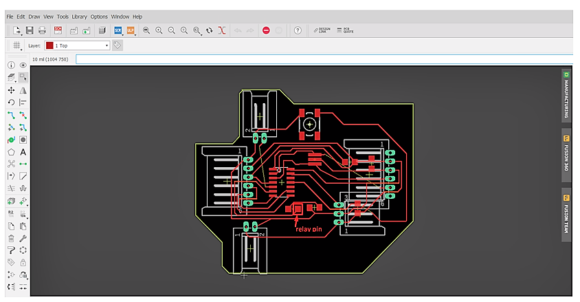
Connecting My Board and the Programmer –
I have powered the Board and the Programmer - programmer (usbasp).
Then, I connected my Programmer to the ISP – header on the LED.
And I ran the normal Blink Program.
Changed the GPIO pin to the pin which is connected to the LED on my
board.
I ran again, it worked.
Then I made a separate GPIO and Ground for the Relay Board, but there
was an issue. It dint work as intended. So, I tried it on the GPIO pin
of my LED and it worked. Then I soldered a wire to the GPIO pin on my
LED and connected it to the Relay. Wow, it worked. Then I was able to
sense the temperature. When it went below 25C it stopped, and when it
went above 25C the DC Fan started working.
Testing Video - Assignment 9 Embedded Programming_files\input output
devices.AVI
Structure of the Pattern – The following 4 steps will
walk through the structure of the pattern of my work in this assignment.
Microcontroller and Microprocessor
Microcontroller has a CPU, in addition with a fixed amount of RAM, ROM
and other peripherals all embedded on a single chip.
Microprocessor is an IC which has only the CPU inside them i.e. only the
processing powers such as Intel's Pentium 1,2,3,4, core 2 duo, i3, i5
etc. ...
.
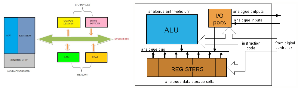
Microcontroller vs Microprocessor
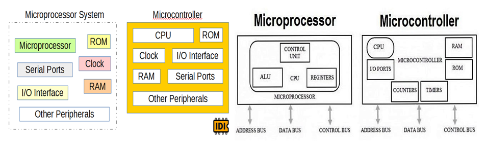
I understand that,
MPU = CPU
MCU = MPU + Peripherals + Memory
Peripherals = Ports + Clock + Timers + UART/USART + ADC + DAC + LCD
Drivers + Other Stuffs
Memory = Flash + SRAM + EPROM + EEPROM
Read the Data Sheet of ATTiny44
I have replaced a LED pin PA7 with a Relay.
Read Datasheet – Explanation of pins
Datasheet is a document that summarizes the performance, technical and
software characteristics in enough detail that anyone can integrate the
component into a system. It usually made by the component
manufacturer.An electronic datasheet specifies characteristics in a
formal structure that allows the information to be processed by a
machine. Such machine readable descriptions can facilitate information
retrieval, display, design, testing, interfacing, verification, and
system discovery.
I used Attiny44 on my pcb so I read and understand it's Datasheet.
http://fab.cba.mit.edu/classes/863.09/people/ryan/week5/ATtiny44%20Data%20Sheet.pdf
This is a 229 page Data Sheet from ATMEL.
My experience of reading the Data Sheet –
I have referred the datasheet to have an understanding about the
Microcontroller as I wanted to know about the operating voltage and the
ADC - Analog Digital Converter which has the ability of converting the
analog value to digital codes. I read parts of the datasheet to fill in
extra detail that is not obvious from the Arduino functions like
changing the PWM frequency produced by analogWrite() ) or to figure out
how to use features that are not part of the standard Arduino functions
like the analog comparator. Each section of the datasheet terminates
with a description of the relevant Registers. All of those registers can
be directly programmed from Arduino code - it "knows" the names of the
registers for example TCCR1B - bits 0,1 and 2 of that byte select the
timer clock speed and hence control the PWM frequency.
After going through the data sheet, I have a general understanding of
how the micro-processors work. Let me submit that I have randomly read
the pages - just not every single page. Now I can "identify" some
elements in an ATMega datasheet. But understanding how they work
together is more involved, especially since the components aren't
"broken out" and everything is hidden on a tiny 28-pin package. For the
components that I can't identify, the datasheet does a good job
explaining what they are but it doesn't provide examples of their use
(like the "example" problems in a calc book). I am now comforatable in
identifying the discrete components - but not really enough to
"understand" the function of small (5-6 discrete components + some
transistors) circuit topology, especially if they involve BJTs/MOSFETs.
It is impossible to use an MCU without following the rules it’s designed
to function. You have to rely on the data sheet only.
Microcontroller
Microcontroller is a Digital Device that is the reason why it needs an
Analog to Digital Convertor.
The ATTiny44 is high Performance, low Power 8-bit Microcontroller with
advanced RISC architecture.
These are its general features:
- 4K Bytes of Flash Program Memory
- 256 Bytes of Programmable EEPROM
- 256 bytes SRAM
- 12 general purpose I/O lines
- 32 general purpose working registers and 8-channel 10-bit ADC.
- Internal calibrated oscillator
- Operating voltage supply between 1.8 ~ 5.5V.
Including 0 there are 8 Analog Input Pins in this Microcontroller. There
are two kinds of Ports in ATTiny44.
Port A pins are 8-bit bi-directional I/O port with internal pull-up
resistors (pin names are from PA0 to PA7)
Port B pins are 4-bit bi-directional I/O port with internal pull-up
resistors (pin names are from PB0 to PB3).
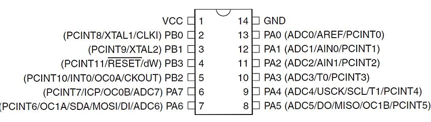
This is the pin layout found in the datasheet:
1. VCC – Supply Voltage
2. PBO - Port B (PB3...PB0)
3. Port B is a 4-bit bi-directional I/O port with internal pull-up
resistors (selected for each bit). The Port B output buffers have
symmetrical drive characteristics with both high sink and source
capability except PB3 which has the RESET capability.
To use pin PB3 as an I/O pin, instead of RESET pin, program (‘0’)
RSTDISBL fuse. As inputs, Port B pins that are externally pulled low
will source current if the pull-up resistors are activated. The Port B
pins are tri-stated when a reset condition becomes active, even if the
clock is not running.
(Port B also serves the functions of various special features of the
ATtiny24A/44A and “Alternate Port Functions” can be reviewed from the
data sheet.)
RESET - Reset input. A low level on this pin for longer than the minimum
pulse length will generate a reset, even if the clock is not running and
provided the reset pin has not been disabled. Shorter pulses are not
guaranteed to generate a reset. The reset pin can also be used as a
(weak) I/O pin.
4. Port A (PA7...PA0) Port A is an 8-bit bi-directional I/O port with
internal pull-up resistors (selected for each bit). The Port A output
buffers have symmetrical drive characteristics with both high sink and
source capability. As inputs, Port A pins that are externally pulled low
will source current if the pull-up resistors are activated. The Port A
pins are tri-stated when a reset condition becomes active, even if the
clock is not running. Port A has alternate functions as analog inputs
for the ADC, analog comparator, timer/counter, SPI and pin change
interrupt as described in “Alternate Port Functions”.
GND – Ground
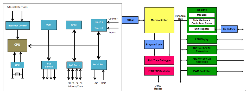
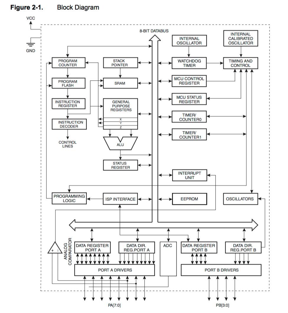
Block Diagram
ATtiny44 is a low-power CMOS 8-bit microcontroller based on the AVR
enhanced RISC architecture. By executing powerful instructions in a
single clock cycle, the ATtiny44 achieves throughputs approaching 1 MIPS
per MHz allowing the system designed to optimize power consumption
versus processing speed. The AVR core combines a rich instruction set
with 32 general purpose working registers. All the 32 registers are
directly connected to the Arithmetic Logic Unit (ALU), allowing two
independent registers to be accessed in one single instruction executed
in one clock cycle. The resulting architecture is more code efficient
while achieving throughputs up to ten times faster than conventional
CISC microcontrollers.
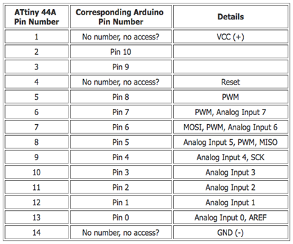
We can also see the corresponding pins in ATTiny44 to Arduino
Microcontrollers
Microcontrollers are whole computer on a chip, but it's a very little
computer. It has CPU (1-20 MHz), Dynamic memory (SRAM), Non-volatile
memory (Flash ROM and EEPROM)
Output
Digital output: Apply 0V or 5V to any pin.
Digital communication: UART, SPI, I2C, USB
Analog Output: Pulse-width Modulation for fake analog. (Arduino's
analogWrite())
Input
Read voltage levels applied to pins
Digital input from pushbuttons and threshold sensors. Receiving digital
Analog-to-Digital Conversion
Input Modes
"Hi-Z": effectively disconnected from the circuit.
Internal pull up resistor: test if anything is connected.
The right strategy to approach microcontroller when doing multiple
things at once is to offload tasks to on-board hardware so that the CPU
stays free and just coordinating the tasks. That's why it is important
to learn the internal hardware peripherals.
The Toolchain
Lifecycle of AVR Programming
Write code in C
Cross-compile for the chip
Transfer the code to the chip
Hardware programmer to talk to the chip.
Software to run the programmer.
Makefile
C is not a free standing language. We need a lot of stuff to compile for
it. This is where Make file comes in.
It keeps track of all the particular setup
It runs all the right command line.
It links in different batches of source file.
It does compile and flash in one step.
Peripherals and their Configuration
Timers: for PWM, counting, timing, scheduling events etc. Using this
well we can write an operating system.
Interrupts: Using interrupts well is what separates a good
microcontroller C programmer from C programmer. It lets us run a
specific routine whenever an event happens which is useful in
monitoring. It pauses the running code and responds to event promptly.
Serial I/O: built-in hardware for USART, SPI, I2C available in AVR
ATMega chips.
Registers
Registers ("Special function registers") are fixed memory locations with
side-effects.
Read and write just like normal variable.
Each register byte is bits - comparable to 8 switches lined up.
Each switch has a side-effect, depends on which register, which bit
PORTB =0b00000010; this sets the PORTB register's value to flip the
number 1 bit (Count from right to left starting from zero) which turns
on PB1.
Input/Output
I/O is also a hardware peripheral.
We use special register DDR (Data direction Registers) to control the
pin's data direction.
DDRB = 0b00000010 sets pin one in PORTB (PB1) into output mode and rest
in Input mode.
Arduino programming vs Embedded C programming
Why C Programming?
Speed: C code runs much faster. Digital Write takes
about 40 cycles in Arduino Code. C code takes one cycle.
Flexibility:strong> Make the hardware peripherals do
what we want and when want them to.
Responsiveness: Using interrupt system well we can do
many things at once, respond instantly
Interrupts are basically events that require immediate attention by the
microcontroller. When an interrupt event occurs the microcontroller
pause its current task and attend to the interrupt by executing an
Interrupt Service Routine (ISR) at the end of the ISR the
microcontroller returns to the task it had pause and continue its normal
operations.
Portability: C is available for every CPU
Code will work on all AVRs
Similarity b/w Arduino Programming and AVR Programming
Control external devices by connecting them to AVR pins.
Communicate with desktop PC over serial.
PWM, ADC, initialization/ event loop structure.
Difference
Different toolchain to program chip.
Configure internal hardware peripherals.
Microcontroller-C programming idioms.
Programming – Steps followed in installing ATTiny library on my laptop.
Programming the board – Please Refer to Assignment 7 Electronics Design
http://fab.academany.org/2019/labs/vigyanashram/students/hemang-vellore/Assignment7/assignment%207%20(Autosaved).htm
Blinking LED code – In this program I have changed the Digital Pin
number 13 to PA7.
Embedded C Program Blink One LED
#include
#include
int main(void)
{
// inits
DDRB |= (1 << PB2); // set data direction register for PB2
as output
// event loop
while (1)
{
PORTB |= (1 << PB2); // turn on led
_delay_ms(250); // delay 250 ms
PORTB = 0; // turn off led
//PORTB &= ~(1 << PB2); // turn off led
_delay_ms(250); // delay 250 ms
}
return (0);
}
Learning Outcome – I learnt that these two commands
avr-gcc and avrdude lead the instruction on my make file. The datasheet
plays a very important role in finding out the pins job on the
microcontrollers. The programing of Microcontroller using Arduino IDE
was interesting. Also understood the different Embedded Programing
Architectures. Realized that soldering / loose connections, calculation
of resistors and capacitors matter a lot for the smooth functioning of
my PCB.
 Reference –
 Fab Academy Tutorials
http://fabacademy.org/2018/docs/FabAcademy-Tutorials/week8_embedded_programming/makefile.html
http://fabacademy.org/2018/docs/FabAcademy-Tutorials/week8_embedded_programming/attiny_c.html
https://circuitdigest.com/article/what-is-the-difference-between-microprocessor-and-microcontroller
https://www.google.com/search?rlz=1C1CHBF_enIN815IN815&ei=SmsOXarVB8r1rQHu_LeICw&q=microcontroller+vs+microprocessor&oq=microcontroller+vs+&gs_l=psy-ab.1.0.0l10.7100285.7651687..7654945...4.0..5.464.4602.0j21j4j1j1......0....1..gws-wiz.....6..0i71j35i39j0i67j0i131j0i131i67.yMJJTODjvQw
http://fab.cba.mit.edu/classes/863.09/people/ryan/week5/ATtiny44%20Data%20Sheet.pdf