Group Assignment:
Probe an Input Device's analog levels and Digital
Signals.
Input Devices
An Input Device is any hardware device that sends
data to a computer or information appliance, allowing you to interact
with and control it. The function of an input device is to communicate
information to a computer or other sort of information processing
equipment. Input devices are types of peripheral devices that
communicate with processing units.
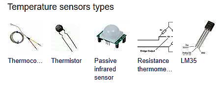
The term sensor is used for an input device that provides a usable
output in response to a specified physical input. For example, a
thermocouple is a sensor that converts a temperature difference into an
electrical output.
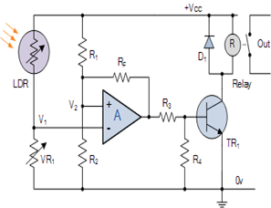
Group Assignment – Our group worked
on LDR - A Light Detector or a Light Sensor is a device or circuit
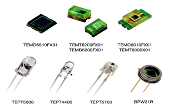
that detects the intensity of the light incident on it. Different
types of light detectors are LDRs (or Light Dependent Resistors),
Photo Diodes, Photo Transistors, etc. A Light Sensor is something that
a robot can use to detect the current ambient light level - i.e. how
bright/dark it is.
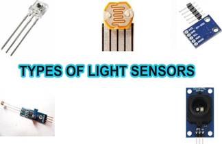
There are a range of different types of light sensors, including
'Photo resistors', 'Photodiodes', and 'Phototransistors'.
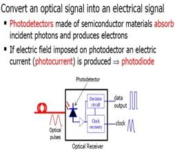
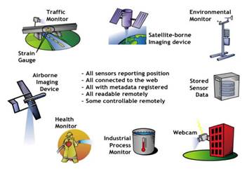
Photodetectors, also called photo sensors, are sensors of light or
other electromagnetic radiation. A photo detector has a p–n junction
that converts light photons into current. The absorbed photons make
electron–hole pairs in the depletion region. We can understand better
through these infographics as seen under.
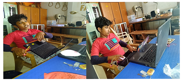
As this week's group assignment is to probe an Input Device's Analog
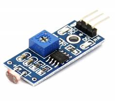
Levels and Digital Signals other Sensors, we have used LDR sensor to
measure the physical quantity using a Microcontroller board.
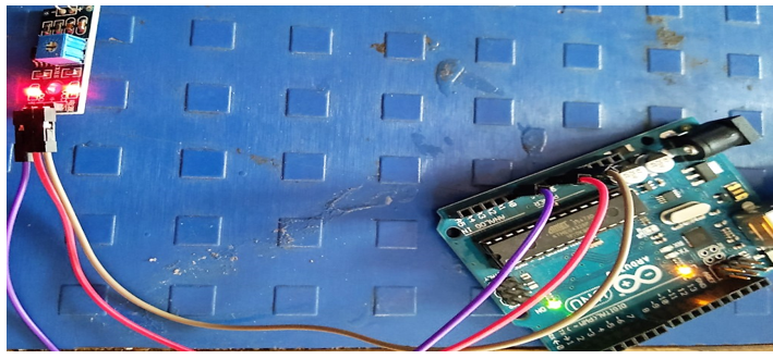
Connected LDR sensor to Arduino
LDR VCC to Arduino 5V
LDR GND to GND
D0 pin to digital pin of Arduino like pin 7
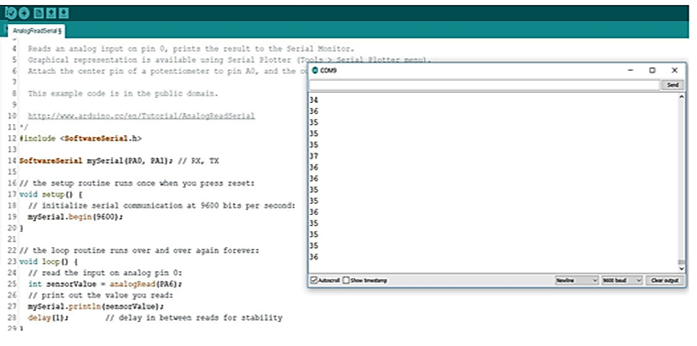
Opened Arduino -->Example --> Basic --> AnalogReadSerial
Connected LDR to Arduino using jumper wires and uploaded program. Got
the output.
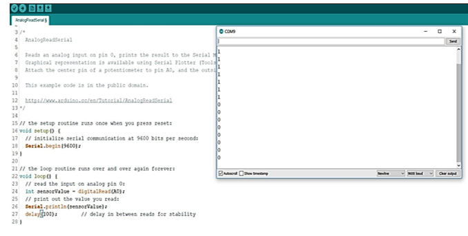
When LDR sensor is in light then got a value 1 or a 0 value.
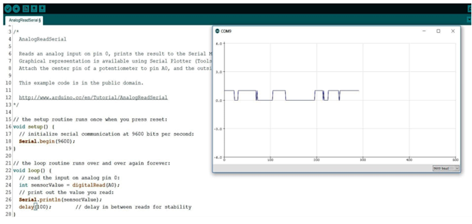
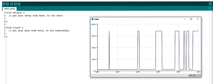
Notice the Sine Waves here.
Can notice the Changing the values as per the intensity of light on the
serial plotter.
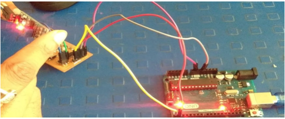
After checking the serial software library, uploaded the program and
connected to the hello echo world board.
The sine waves as Output after uploading the program on the hello echo
world board.
 Individual Assignment:
Measure something and add a
sensor to a microcontroller board that you have designed and read it.
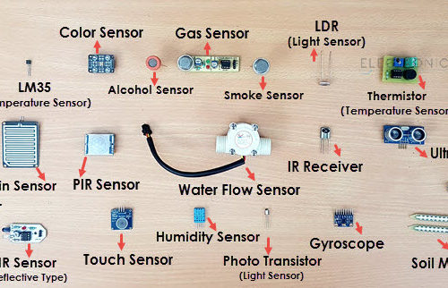
An Electronic System or circuit must be able or capable to “do”
something and Sensors and Transducers are the perfect components for
doing this task. The Sensors are Input Devices that record data about
the physical environment. By measuring the change in heat, the sensor
can detect changes in temperature. The Devices which perform an “Input”
function are commonly called Sensors because they “sense” a physical
change in some characteristic that changes in response to some
excitation, for example, heat or force and convert that into an
electrical signal. There are various types of sensors as seen below.
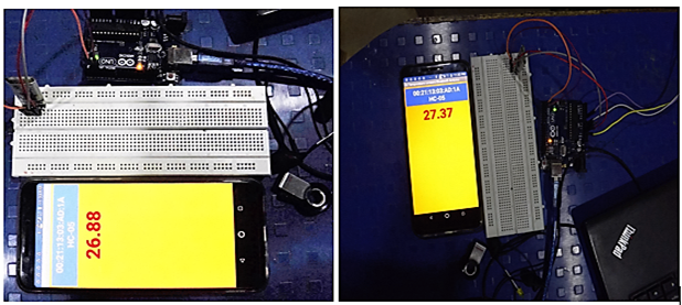
I wanted to add an Input Device to my final project, so I have decided
to try Temperature Sensor LM 35. The idea is to have a Display for Room
Temperature through the Temperature Sensor mounted on the top of the
Smart Air Cooler via Bluetooth module HC05 on a Mobile Application.
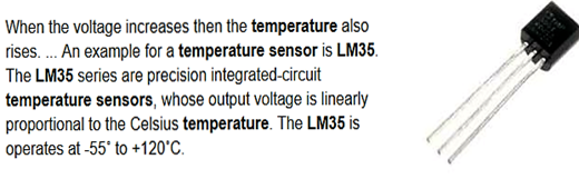
The LM35 series are precision integrated-circuit temperature devices
with an output voltage linearly-proportional to the Centigrade
temperature.
The LM35 Input Device has the following features -
Operating temperature range(C) : -40 to 110; -55 ...
Sensor gain (mV/Degree C) : 10
Local sensor accuracy (Max) (+/- C) : 0.5
Output impedance (ohms) : 0.4
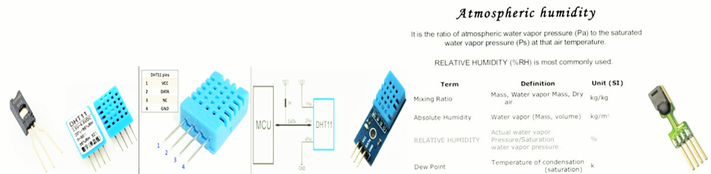
After reading about the Temperature Sensor LM35, I went through the
Humidity Sensor DHT11, which senses both the moisture and the air
temperature. So I went ahead. The Relative Humidity expressed as a
percent is the ratio of the actual moisture in the air to the highest
amount of moisture air at which the temperature can hold. The types of
Humidity Sensors are listed below.
 Humidity Controller –
 Humidity is the presence of
water in the air. The presence of water vapor also influences various
physical, chemical and biological processes. Humidity measurement is
critical in industries, as it affects the business cost of the product
and the health and safety of its personnel. Hence Humidity sensing is
very important especially in control systems for industrial processes
and human comfort. In order to avoid the problems of excess moisture, it
is necessary to limit or control the amount of vapor in the
surroundings.
DHT11 Temperature and Humidity Sensor. This DHT11 Temperature and
Humidity Sensor features a calibrated digital signal output with the
temperature and humidity sensor capability. It is integrated with a
high-performance 8-bit microcontroller. Its technology ensures the high
reliability and excellent long-term stability. This sensor includes a
resistive element and a sensor for wet NTC temperature measuring
devices. It has excellent quality, fast response, anti-interference
ability and high performance.
Each DHT11 sensors features extremely accurate calibration of humidity
calibration chamber. The calibration coefficients stored in the OTP
program memory, internal sensors detect signals in the process, called
as Calibration Coefficients. The single-wire serial interface system is
integrated to become quick and easy. Small size, low power, signal
transmission distance up to 20 meters, enabling a variety of
applications and even the most demanding ones. The product is 4-pin
single row pin package. Convenient connection, special packages can be
provided according to users need.
Where to use DHT11:
The DHT11 is a commonly used Temperature and humidity sensor. The sensor
comes with a dedicated NTC to measure temperature and an 8-bit
microcontroller to output the values of temperature and humidity as
serial data. The sensor is also factory calibrated and hence easy to
interface with other microcontrollers. The sensor can measure
temperature from 0°C to 50°C and humidity from 20% to 90% with an
accuracy of ±1°C and ±1%.
Difference between DHT11 Sensor and module:
The DHT11 sensor can either be purchased as a sensor or as a module.
Either way, the performance of the sensor is same. The sensor will come
as a 4-pin package out of which only three pins will be used whereas the
module will come with three pins as shown below.
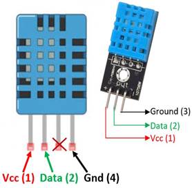
The only difference between the sensor and module is that the module
will have a filtering capacitor and pull-up resistor inbuilt, and for
the sensor, you have to use them externally if required.
Pin Identification and Configuration for Sensor:
| SL.No |
Pin Name |
Description |
| 1 |
VCC |
Power supply 3.5V to 5.5V |
| 2 |
Data |
Outputs both Temperature and Humidity through Serial Data |
| 3 |
NC |
No Connection and hence not used |
| 4 |
Ground |
Connected to the ground of the circuit |
Pin Identification and Configuration for Module:
| SL.No |
Pin Name |
Description |
| 1 |
VCC |
Power supply 3.5V to 5.5V |
| 2 |
Data |
Outputs both Temperature and Humidity through Serial Data |
| 3 |
Ground |
Connected to the ground of the circuit |
Specifications of Humidity Sensor -
Operating Supply Voltage: 3.5v to 5.5 V
Temperature range: 0-50 °C error of ± 2 °C
Humidity: 20-90% RH ± 5% RH error
Interface: Digital
Operating current: 0.3mA (measuring) 60uA (standby)
Output: Serial data
Resolution: Temperature and Humidity both are 16-bit
Accuracy: ±1°C and ±1%
Data Sheet -
https://components101.com/sites/default/files/component_datasheet/DHT11-Temperature-Sensor.pdf
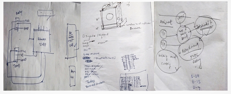
Mind Mapping My Idea -
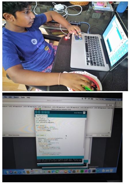
It dint not work, so I tried to reinstall the driver and it worked.
In the Code, the ATTiny Pins should be used in their equivalent numbers
in Arduino Boards.
I had a problem with Arduino ide. I could not install ATTiny after that.
Finally after trials, it worked.
Programed in Aurdiuno IDE
I have tried this idea of water auto refill for the water storage tank
of my final project, Smart FAB Air Cooler.
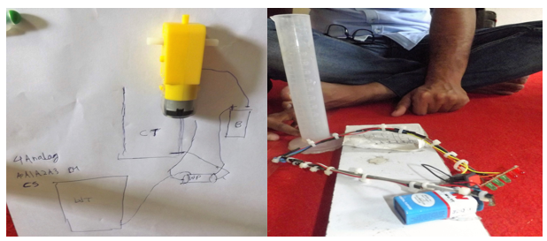
But was not doable on my board. So later, will integrate the same.
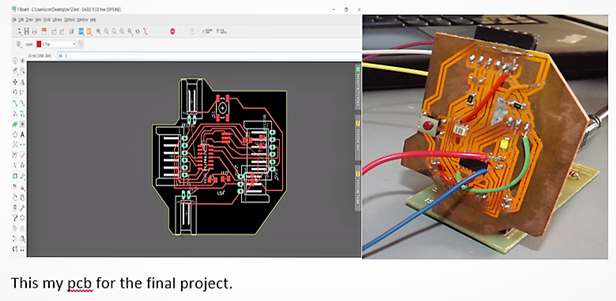
PCBI have milled a new PCB for Input and Output
Assignments powered by ATTiny45.
PCB Milling Video -
https://youtu.be/ua7fWLVYzR4
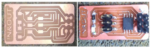
Design File - Assignment
12 Output Device_files\in and out.brd
int sensorPin = PB4;
int ledPin1 = PB3;
//int ledPin2 = 4;
int sensorValue = 0;
float volts=0.0,temp=0.0;
void setup() {
pinMode(ledPin1, OUTPUT);
//pinMode(ledPin2, OUTPUT);
//Serial.begin(9600);
}
void loop() {
sensorValue = analogRead(sensorPin);
volts= sensorValue*5.0/1023;
temp = volts*100;
//Serial.print("Temprature is");
//Serial.print(temp);
if(temp > 30) {
digitalWrite(ledPin1,HIGH);
//digitalWrite(ledPin2,LOW);
}
else {
//digitalWrite(ledPin2,HIGH);
digitalWrite(ledPin1,LOW);
}
delay(100);
}
Group Assignment: I have teamed up with Jaydip for
this assignment.
Video Link:
https://youtu.be/WtnyGXJUNsA
Learning Outcome –
I have learnt to integrate sensors on my PCB after having an idea about
the various sensors, while understanding how to setup communication
between the board and the laptop to get the readings of the sensor on
the serial monitor.
The concept of serial port, programmer memory, check the display, View
the result and graphs on the serial monitor and how to select the sensor
and microcontroller as per our application were indeed a great learning.
Reference – FAB Academy modules and Internet
https://electronicsforu.com/electronics-projects/automatic-water-refiller-air-coolers
https://www.robot-r-us.com/vmchk/sensor-temp/humid/dht11-temperature-and-humidity-sensor.html
https://components101.com/dht11-temperature-sensor