I had to gain hands on experience as I didn’t have previous technical knowledge on this subject.
Task This week the goal is to Design, Build and Connect a Wired or a Wireless Node which is preferably useful for the final project.
Send a message between two projects.
Networking is the interconnection of multiple devices, using multiple
paths for the sending or receiving data or media. This data transfers
through cable or wires or optic cables, or wireless media such as
Wi-Fi. Data communication refers to the transmission of the digital
data between two or more computers. The physical connection bet
ween networked computing devices is established using either cable
media or wireless media. The best-known computer network is the
Internet.
Data communication refers to the exchange of data between a source and
a receiver via form of transmission media such as a wire cable. Data
communication is said to be local if communicating devices are in the
same building or a similarly restricted geographical area. The
meanings of source and receiver are very simple. The device that
transmits the data is known as source and the device that receives the
transmitted data is known as receiver. Data communication aims at the
transfer of data and maintenance of the data during the process but
not the actual generation of the information at the source and
receiver.
Datum mean the facts information statistics or the like derived by
calculation or experimentation. The facts and information so gathered
are processed in accordance with defined systems of procedure. Data
can exist in a variety of forms such as numbers, text, bits and bytes.
The Figure is an illustration of a simple data communication system.
The 11 Types of Networks in Use Today
1. Personal Area Network (PAN)
The smallest and most basic type of network, a PAN is made up of a
wireless modem, a computer or two, phones, printers, tablets, etc.,
and revolves around one person in one building. These types of
networks are typically found in small offices or residences, and are
managed by one person or organization from a single device.
2. Local Area Network (LAN)
LANs are the most frequently discussed networks, one of the most
common, one of the most original and one of the simplest types of
networks. LANs connect groups of computers and low-voltage devices
together across short distances (within a building or between a group
of two or three buildings in close proximity to each other) to share
information and resources. Enterprises typically manage and maintain
LANs. Using routers, LANs can connect to wide area networks (WANs,
explained below) to rapidly and safely transfer data.
3. Wireless Local Area Network (WLAN)
Functioning like a LAN, WLANs make use of wireless network technology,
such as WiFi. Typically seen in the same types of applications as
LANs, these types of networks don’t require that devices rely on
physical cables to connect to the network.
4. Campus Area Network (CAN)
Larger than LANs, but smaller than metropolitan area networks (MANs,
explained below), these types of networks are typically seen in
universities, large K-12 school districts or small businesses. They
can be spread across several buildings that are fairly close to each
other so users can share resources.
5. Metropolitan Area Network (MAN)
These types of networks are larger than LANs but smaller than WANs –
and incorporate elements from both types of networks. MANs span an
entire geographic area (typically a town or city, but sometimes a
campus). Ownership and maintenance is handled by either a single
person or company (a local council, a large company, etc.).
6. Wide Area Network (WAN)
Slightly more complex than a LAN, a WAN connects computers together
across longer physical distances. This allows computers and
low-voltage devices to be remotely connected to each other over one
large network to communicate even when they’re miles apart. The
Internet is the most basic example of a WAN, connecting all computers
together around the world. Because of a WAN’s vast reach, it is
typically owned and maintained by multiple administrators or the
public.
7. Storage-Area Network (SAN)
As a dedicated high-speed network that connects shared pools of
storage devices to several servers, these types of networks don’t rely
on a LAN or WAN. Instead, they move storage resources away from the
network and place them into their own high-performance network. SANs
can be accessed in the same fashion as a drive attached to a server.
Types of storage-area networks include converged, virtual and unified
SANs.
8. System-Area Network (also known as SAN)
This term is fairly new within the past two decades. It is used to
explain a relatively local network that is designed to provide
high-speed connection in server-to-server applications (cluster
environments), storage area networks (called “SANs” as well) and
processor-to-processor applications. The computers connected on a SAN
operate as a single system at very high speeds.
9. Passive Optical Local Area Network (POLAN)
As an alternative to traditional switch-based Ethernet LANs, POLAN
technology can be integrated into structured cabling to overcome
concerns about supporting traditional Ethernet protocols and network
applications such as PoE (Power over Ethernet). A point-to-multipoint
LAN architecture, POLAN uses optical splitters to split an optical
signal from one strand of single mode optical fiber into multiple
signals to serve users and devices.
10. Enterprise Private Network (EPN)
These types of networks are built and owned by businesses that want to
securely connect its various locations to share computer resources.
11. Virtual Private Network (VPN)
By extending a private network across the Internet, a VPN lets its
users send and receive data as if their devices were connected to the
private network – even if they’re not. Through a virtual
point-to-point connection, users can access a private network
remotely.
Components or Elements of a Data Communication:
Message
Sender
Receiver
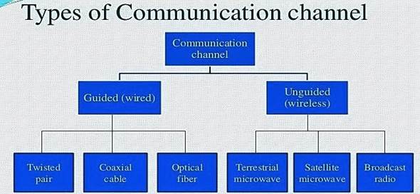
Medium (Communication Channel)
Protocols - Encoder & Decoder
The effectiveness depends on four fundamental characteristics of data
communications.
1. Delivery: The data must be deliver in correct order with correct
destination.
2. Accuracy: The data must be deliver accurately.
3. Timeliness: The data must be deliver in a timely manner. Late
delivered Data useless.
4. Jitter: It is the uneven delay in the packet arrival time that
cause uneven quality.
How are data presented in data communication?
The term telecommunication means communication at a distance. The word
data refers to information presented in whatever form is agreed upon
by the parties creating and using the data. Data communications are
the exchange of data between two devices via some form of transmission
medium such as a wire cable.
What is data communication and its types?
Communication means the exchange of information or messages. The
process of transferring data from one location to another is called
Data Communication.
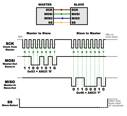
There are two methods used to transmit data between digital devices:
serial transmission and parallel transmission.
Serial data transmission sends data bits one after another over a
single channel. It is Synchronous and Asynchronous.
Parallel data transmission sends multiple data bits at the same time
over multiple channels.
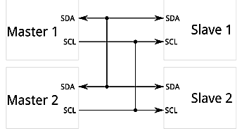
Serial bus –

#include
void setup() {
Wire.begin(); // join i2c bus (address optional for master)
Serial.begin(9600); // start serial for output
Serial.println("Waiting for Data");
}
void loop() {
Wire.requestFrom(8, 6); // request 6 bytes from slave device #8
while (Wire.available()) { // slave may send less than requested
char c = Wire.read(); // receive a byte as character
Serial.print(c); // print the character
}
delay(500);
}
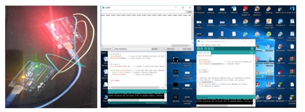
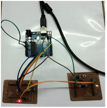
Then I have uploaded the Slave Code –
#include
void setup() {
Wire.begin(8); // join i2c bus with address #8
Wire.onRequest(requestEvent); // register event
}
void loop() {
delay(100);
}
// function that executes whenever data is requested by master
// this function is registered as an event, see setup()
void requestEvent() {
Wire.write("hi mom"); // respond with message of 6 bytes
// as expected by master
}
#include
#define X_Axis A0
#define Y_Axis A1
#define Switch A3
SoftwareSerial Bluetooth(2,3); // pin2- connected to bluetooth Tx
// pin3- connected to bluetooth Rx
void setup() {
// put your setup code here, to run once:
Serial.begin(9600);
Bluetooth.begin(9600);
pinMode(A3,INPUT_PULLUP);
}
void loop() {
// put your main code here, to run repeatedly:
int x_axis, y_axis;
x_axis = analogRead(X_Axis);
y_axis = analogRead(Y_Axis);
if(x_axis > 750){
Serial.print("R");
delay(2000);
}
else if(x_axis < 250){
Serial.print("R");
delay(2000);
}
if(y_axis > 750){
Serial.print("F");
delay(100);
}
else if(y_axis < 250){
Serial.print("B");
delay(100);
}
if(x_axis < 600 && x_axis > 450 && y_axis <
600 && y_axis > 450){
Serial.print("S");
delay(100);
}
}
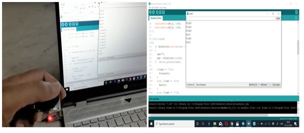
Code – For operating the Cable Bot with Bluetooth
#include
#define M_L1 4
#define M_L2 5
#define M_R1 6
#define M_R2 7
char cmd = 0;
SoftwareSerial Bluetooth(2, 3); // pin2- connected to bluetooth Tx
// pin3- connected to bluetooth Rx
void setup() /****** SETUP: RUNS ONCE ******/
{
Serial.begin(9600);
Bluetooth.begin(9600);
pinMode(M_L1, OUTPUT);
pinMode(M_L2, OUTPUT);
pinMode(M_R1, OUTPUT);
pinMode(M_R2, OUTPUT);
digitalWrite(M_R1, LOW);
digitalWrite(M_R2, LOW);
digitalWrite(M_L1, LOW);
digitalWrite(M_L2, LOW);
}
void loop()
{
if (Bluetooth.available() > 0)
{
cmd = Bluetooth.read();
if(cmd == 'F'){
Forward();
}
else if(cmd == 'B'){
Back();
}
else if(cmd == 'L'){
Left();
}
else if(cmd == 'R'){
Right();
}
else if(cmd == 'S'){
Stop();
}
}
}
void Forward() {
digitalWrite(M_R1, LOW);
digitalWrite(M_R2, HIGH);
digitalWrite(M_L1, LOW);
digitalWrite(M_L2, HIGH);
delay(100);
}
void Back() {
digitalWrite(M_R1, HIGH);
digitalWrite(M_R2, LOW);
digitalWrite(M_L1, HIGH);
digitalWrite(M_L2, LOW);
delay(100);
}
void Left() {
digitalWrite(M_R1, LOW);
digitalWrite(M_R2, HIGH);
digitalWrite(M_L1, LOW);
digitalWrite(M_L2, LOW);
delay(1000);
Stop();
}
void Right() {
digitalWrite(M_R1, LOW);
digitalWrite(M_R2, LOW);
digitalWrite(M_L1, LOW);
digitalWrite(M_L2, HIGH);
delay(1000);
Stop();
}
void Stop() {
digitalWrite(M_R1, LOW);
digitalWrite(M_R2, LOW);
digitalWrite(M_L1, LOW);
digitalWrite(M_L2, LOW);
}
//--(end main loop )---