Displacement Tracks
Bearing system which enables the movement of the machine
Analyzing the Previous System
The previous bearing system was designed using CAD and made with CAM and also buying some parts.
- Material: Plywood
- Fasteners: Nylon insulating washer
- Guide: Linear motion shafts
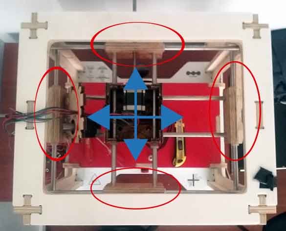
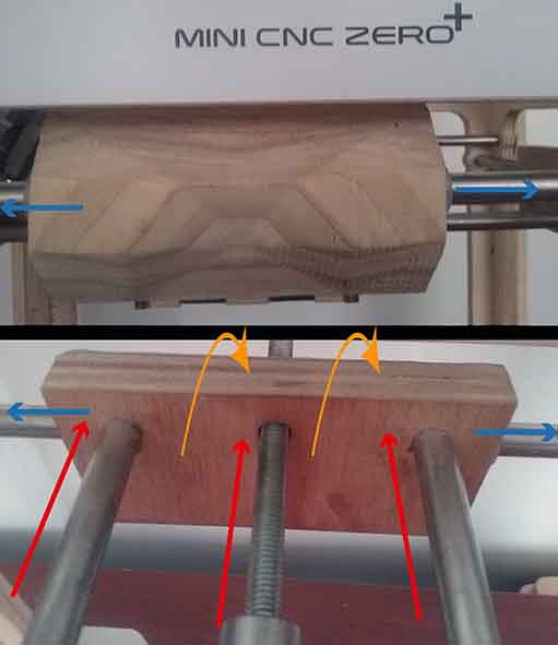
One problem of the previous design was about that the machine wasn't too accurate because of the X and Z axes guides being at different levels causing the piece to act as a pivot when it was operating.
New Design
To correct that issue this new design proposes to put the guides located at the same level. For that I used Freecad to create the new design of the bearing system with the following work flow:
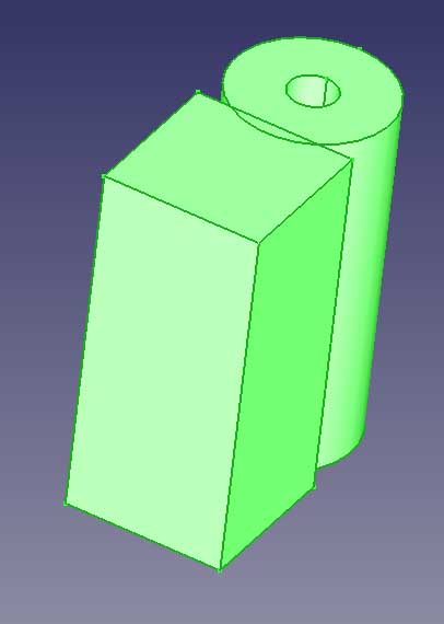
FreeCAD
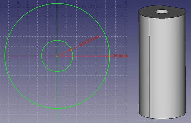
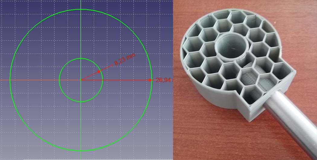
- Create a new sketch in the sketcher workbench and draw one circle with another one in the interior and radius constrain to each one (the dimension of the interior circle is in relationship with the actual nylon insulation washer and the external circle dimension was made considering the actual size of the guides). Using the part workbench I extruded the cylinder.
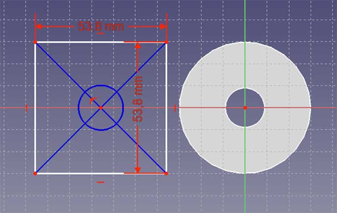
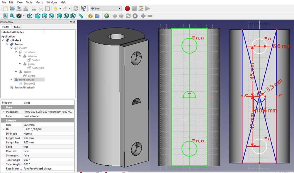
- Create a new sketch attached to the X, Y plane and create a square with a vertical and horizontal distance constrains and also centering the figure using this tutorial as reference. After that I extrude the cilinder to form a prism.
- I put the the figures close to each other and using the slice boolean in the part workbench operation I split the ofjects where they intersect.
- Create a new sketch attached to the flat face and center the sketch using the construction mode to create guidelines and also vertical and radius constrains between the figures to get the desired dimensions. After that extrude the figures and using the slice boolean operation subtract the shapes. The I use parametric design to easily change any dimension if is needed.
- Finally in the mesh design work bench I create a mesh from a shape using the standard configuration to finally be exported as a STL file.

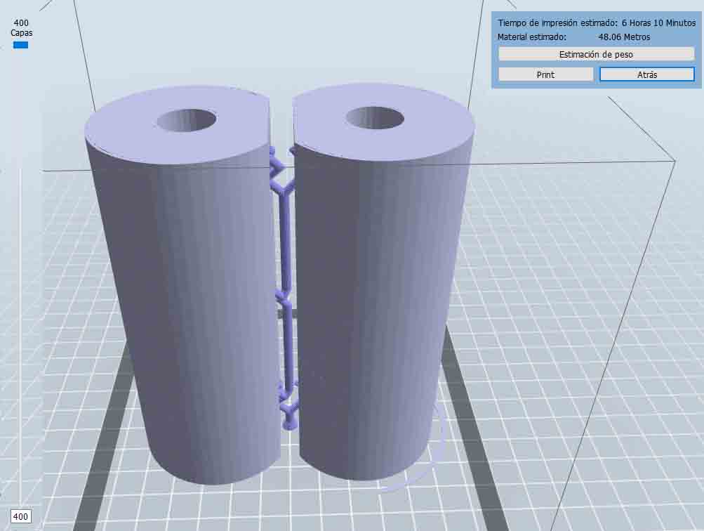
Flash Print (3D Printing Software)
Is a slice software used by FlashForge 3D printer. Work flow:
- Open the software.
- Load the STL file and move it to the desired position and again load the same file and rotate and locate to the desired position. I realized that if I put one in from of the other when I generate the supports they are created in between of then serving for both.
- Supports:
- Type: dendritic
- Base diameter: 6 mm
- Post diameter: 3mm
- Base tall: 3mm
- Auto support.
- Print settings:
- Resolution: Low (Faster)
- Layer height: 0.3mm
- Perimeter structure: 2
- Superior and bottom solid layers: 3
- Infill: 10%
- Pattern density: Hexagon
- Speed:80nm/s
- Trajectory speed:: 100mn/s
- Extruder temperature: 220C
- Accept and save the GCode.
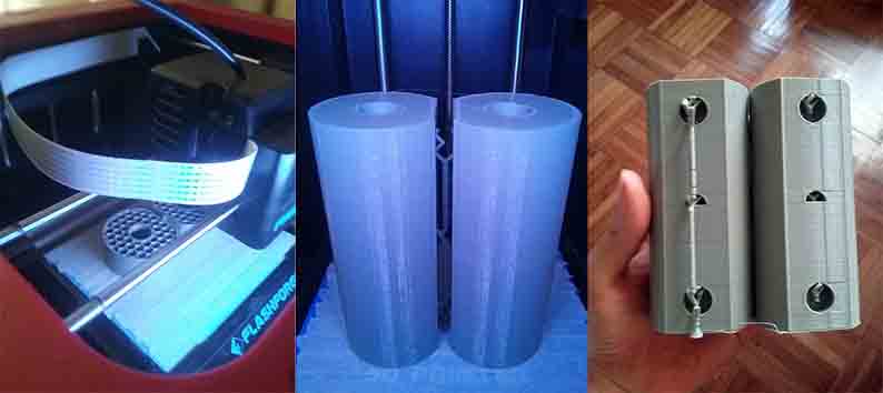
Printing (FlashForge Finder-hardware)
First I had to level the 3d printer this process was very easily because the machine had a sensor and I just need to adjust the screws. Also the bed of the printer needs be protected using scotch tape which is covered by a layer of stick glue. And after 6 and a half hours the cylinder guides are ready to be tested.
TESTING THE 3D PRINTED BEARING SYSTEM
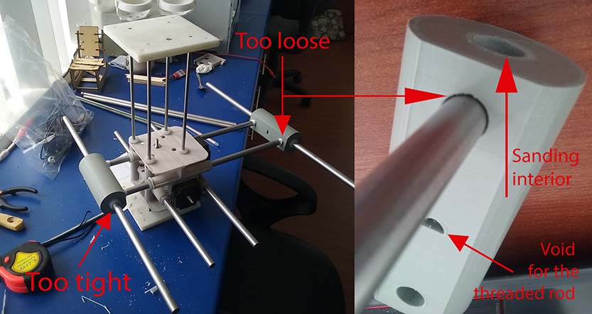
Problem:
When I assembly the 3d printed bearing system with the linear motion shafts and the 3d printed motor holder made by Jorge the 9 cm distance between the axis was ok but the holes for nylon insulation washers was too tight and the holes for the linear motor shafts were too loose so for this time I had to use thread seal tape to secure the linear motor shafts to the holes. Also I had to use a drill dremel to sand the interior of the 3d printed bearing system so the nylon insulation washer can fit well and the linear motor shafts can slide easily.
Debugging:
First I changed the size diameter of the interior hole from 16.125 mm to 16.46 mm leaving a tolerance of 0.28 mm. A tolerance of 0.30 mm will be better. With a tolerance of 0.32 mm the fasteners are too loose from the 3d printed bearing system and the press fit doesn't work to good.
The second thing I changed was the diameter dimension of the two front side holes from 12.65 mm to 13.2 mm leaving a tolerance of 0.5 mm.
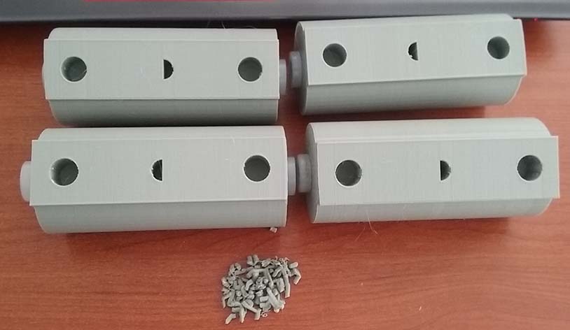
After that I add a extrusion of 6 mm at the front side leaving the holes with a depth of 15 mm because the linear motor shafts should be attached to the bearing system as a press-fit.
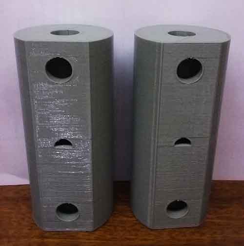
The result of the tests was very good with a few observations:
- Lateral holes: in the 3d printing process the base side of the pieces are a bit tight but the top side is very good also the pieces need to be sanded to let the pieces slide without problem.
- Front holes: the linear motor shafts fit very well as a press-fit.
- Middle half hole: I leave a tolerance of 0.5 mm.
You can download the files:
Assembly the parts: we achieve the goal of build the mechanical parts and operate it manually.
Motor position system made by Jorge, Casing made by Ale, Bearing system made by me
Conclusion:
Digital fabrication allow us to design and produce our own parts individually and after assemble all of them to create a system.
If we are going to create pieces that has to fit together is better to make little test and find the right tolerances.
Starting from a previously developed design helped us a lot to understand how the machine work and from that design we analyzed the most weak points of the mechanism and we improved it.