Motion control
Electronic System of the Machine
Motion control
PREVIOUSLY DESIGN 2018
The CNC shield developed by the students of the fabacademy 2018 and designed by Alex worked well but it doesn't look very good because the DC power Jack supply was loose from the shield.
Zero CNC Electronic configuration 2018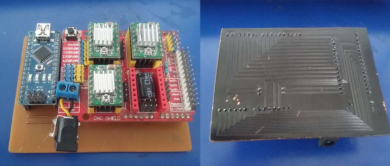
Arduino nano
The Arduino Nano is a small, complete, and breadboard-friendly board based on the ATmega328P. Works with a Mini-B USB cable. Tech specs.
3-Axis CNC/Stepper Motor Shield for arduino
It uses opensource firmware on Arduino to control 4 stepper motors using 4 pieces of A4988 Stepper Motor driver breakout board, with this shield and ArduinoUno/Mega. Datasheet.
NEW DESIGN 2019
So we decided to improve the design and attach the DC power supply to the board.
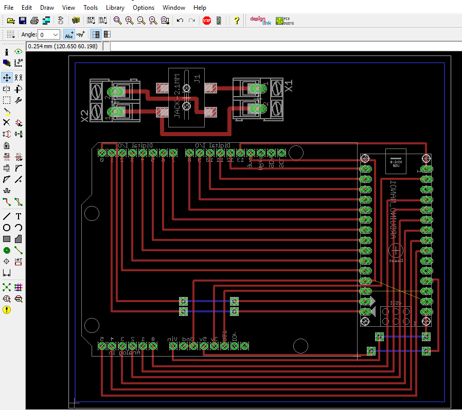
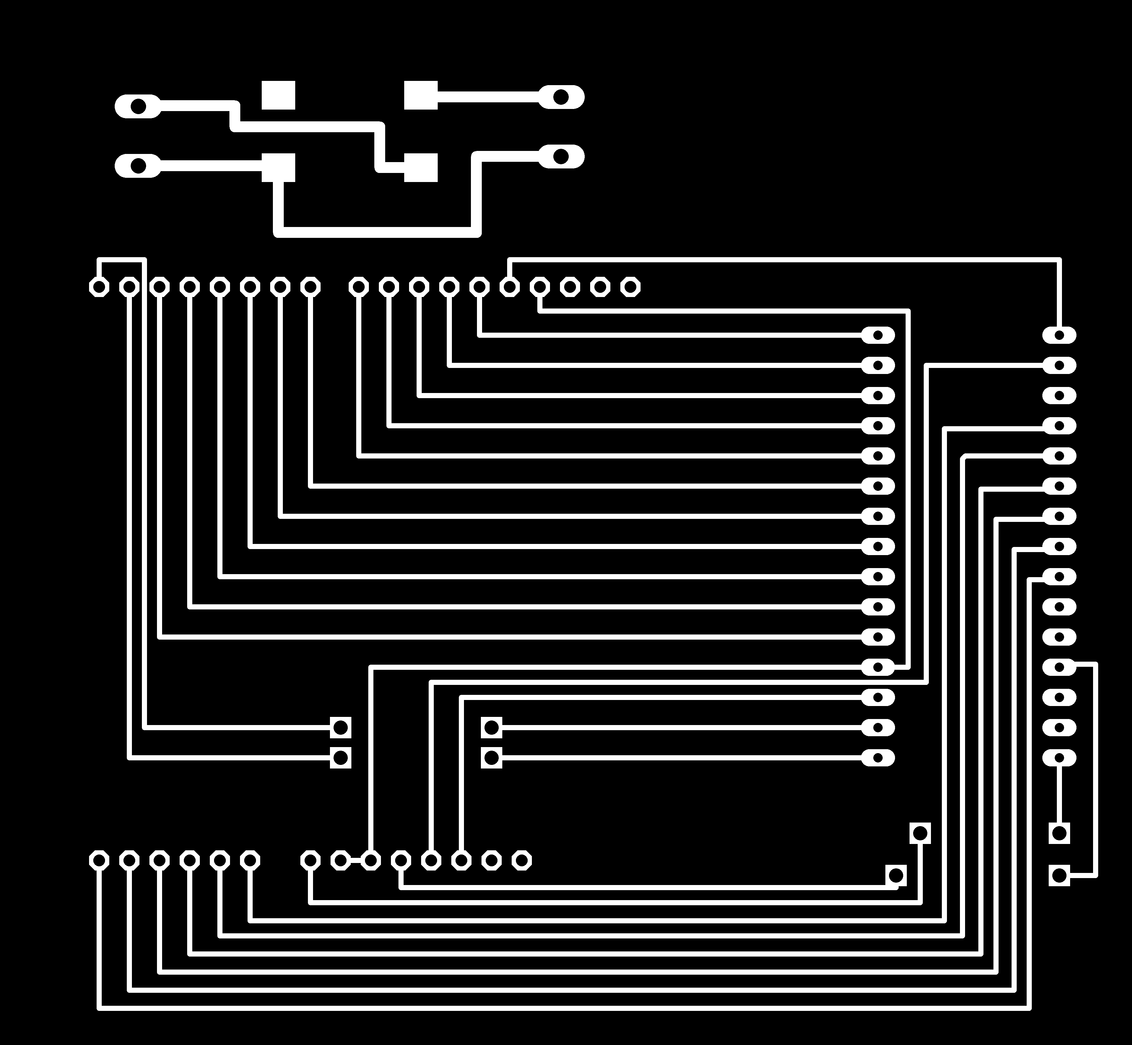
Eagle
- Schematic:
- Board:
- PNG files:
I add three new components to the file a DC Power Jack which will feed the motors and the spindle through two terminals (AK300/2) connected through cables.
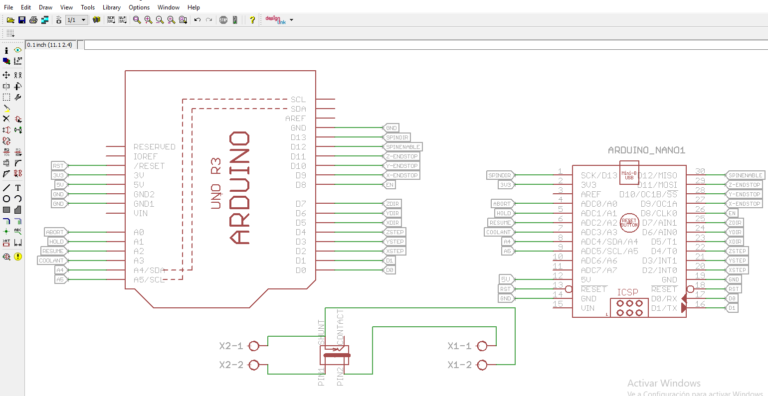
The idea for the design was to place the power supply of 5V and 12V at the same side to make easier the connection.

You can download the files:
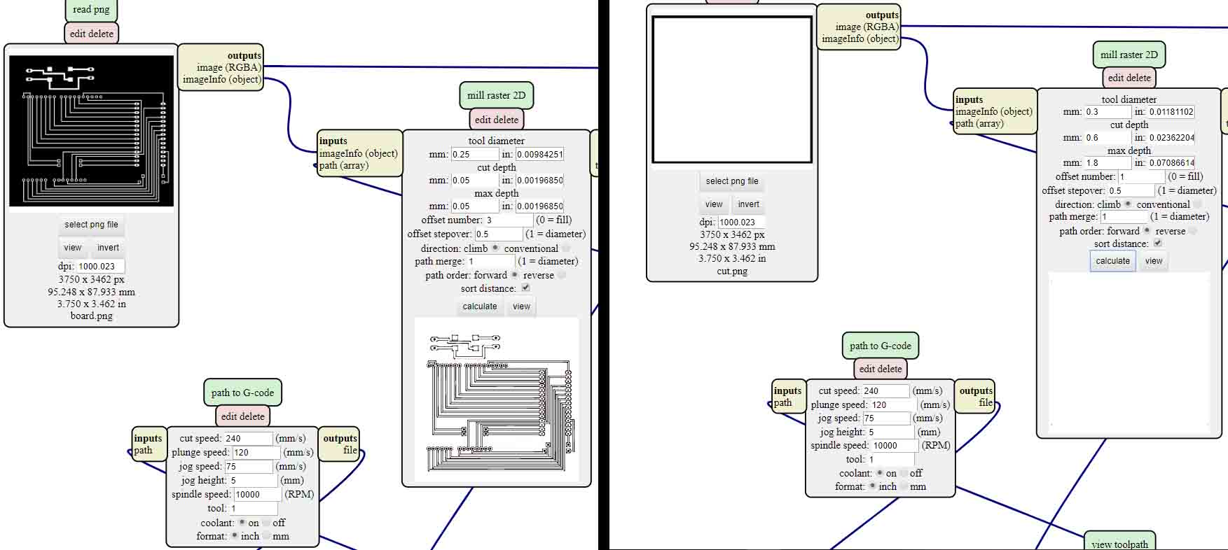
Mods
I had to make some tests until reach the desired result and this are the settings:
- Tool diameter: 0.25 mm
- Cut depth: 0.05 mm
- Max depth: 0.05
- Offset number:3
- Offset stopover:0.5
- Cut speed: 240
Traces
- Tool diameter: 0.3 mm
- Cut depth:0.6 mm
- Max depth: 1.8 mm
- Offset number: 1
- Offset stopover: 0.5
Cut
You can download the files:
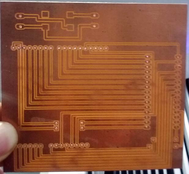
Machining
The milling tool was a new one of 60 degrees and I had to use a Dremel to drill the holes in to the PCB also a blade to separate two traces that the CNC didn't cut.
Solder
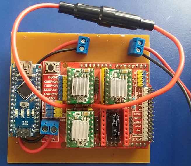
I had to use PBC connectors to connect the systems mounted on PCBs and transfer signals or power from one PCB to another. I use this two types:
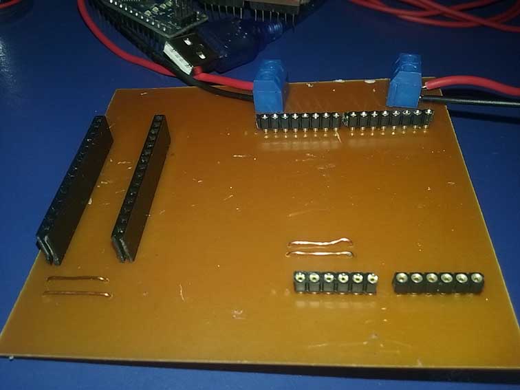
After soldering all the connectors I mount the CNC shield and the arduino nano on the board and connect the terminals with the power supply trough cables.
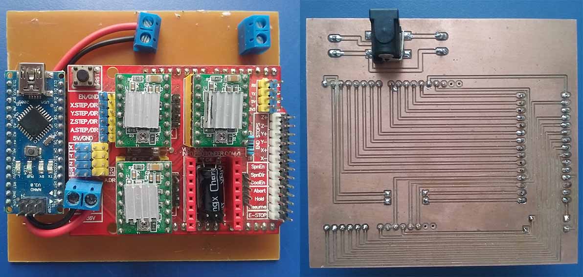
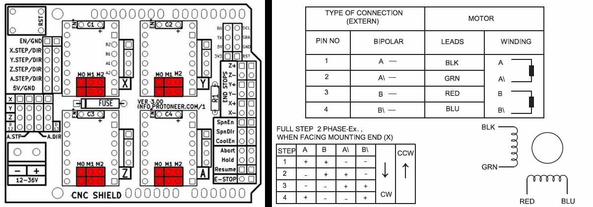
Motor connections
To connect the motor cables we need to review the Nema stepper motor data sheet and also the CNC shield datasheet to know the right order in relationship with the colors of the cables.
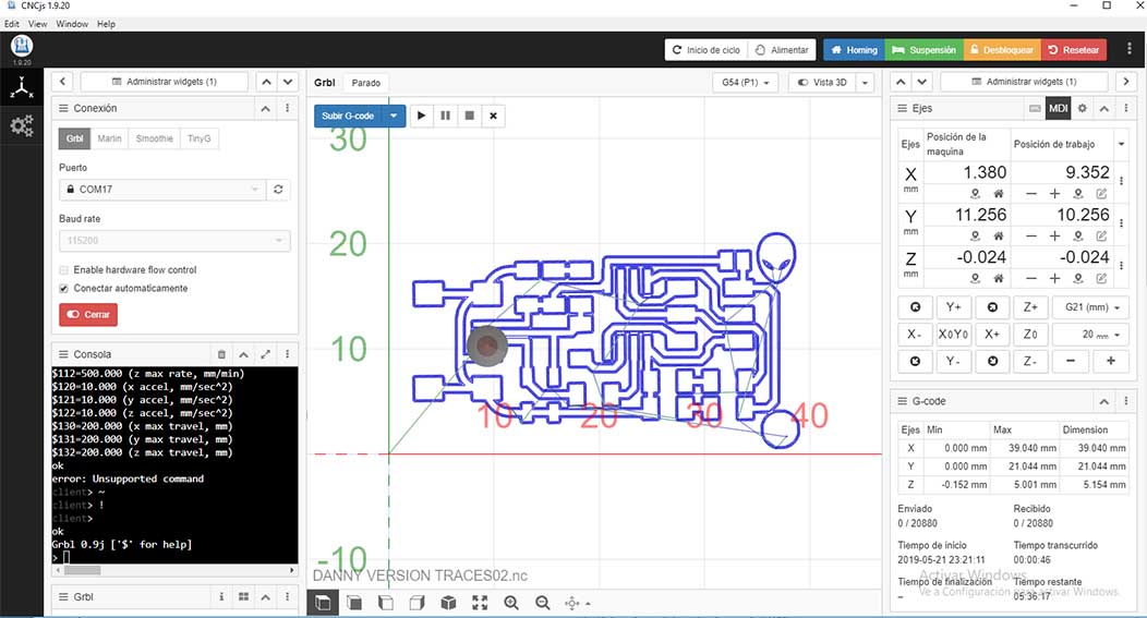
Software:
CNCJS is a web-based interface for CNC milling controller running Grbl, Smoothieware, or TinyG. It runs on an Raspberry Pi or a laptop computer that you have Node.js installed. We download the app from this link.
The students of the fabacademy 2018 program the arduino nano so we just need to connect the shield to the PC. You can check the process at this link. After installing the app we did the next workflow:
- To test what the is happening with the board we connect to the PC and open arduino software and open the serial monitor and the answer the board is giving us was a letter F.
- After that we open the CNC JS app, refresh and choose the right port.
- Connect and open and the console start running.
- The first motor we test was the X axis so we started moving from the software an it works!
- And finally we connect the Y axis motor and it work also.
Problem
As you can see in the video the voltage is 8.8 and the current is 2.7 at that moment we didn't know what's happening and we started increasing the voltage until reach 12 volts and the motors stop working. So we had to test the motors to know if they were not burned for that I use my easy driver and they were ok.
So another possibility was about the software so we try to upload the GRBL with Arduino 1.8.8 version and the software doesn't recognize the library and after trying with other versions of arduino the 1.6 version work very well and we realized that the software wasn't the problem.
Other possibility was about a blown fuse and that was the problem.
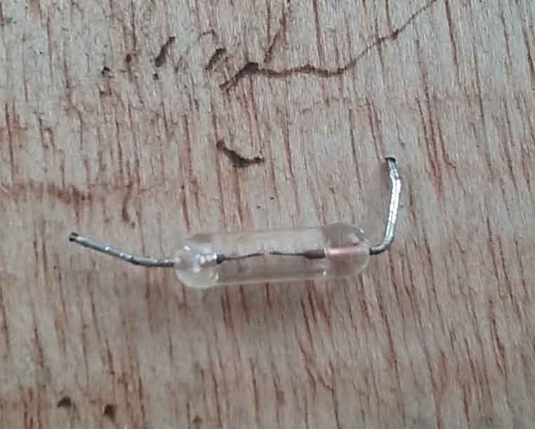
Debugging
I had to desolder the component from the board and solder an external fuse using a fuse holder and a fuse of 2 amps. It' better if we had the fuse out of the board in case it blown so we can replace easily.
After doing that we had to figure why the current and voltage was varying to much and we realized that the drivers had to be configured and for that with Alex help we did the next work flow:
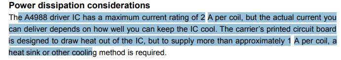
- Review the driver A4988 data sheet. And we found that the courrent rating is 2A so with a 2A fuse was fine.
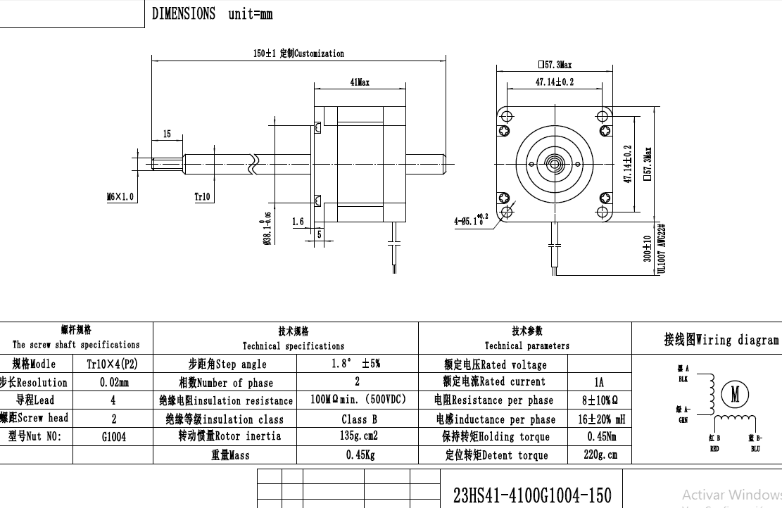
- Review the stepper motor data sheet. We found that the rated current was 1A.
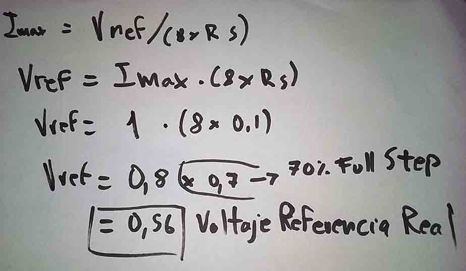
- Watch this tutorial where explain the right way to calibrate the driver. And we did the next calculations to find the real voltage reference.
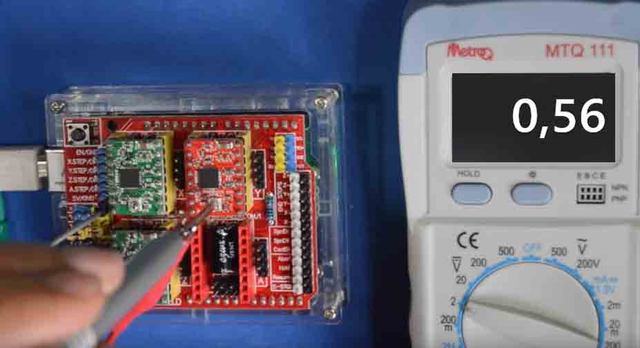
- Calibrate the motors with the help of a multimeter connected the reference to GND and the other side to the metallic part of the screwdriver.
- After fixing that issues the motors start working very well.
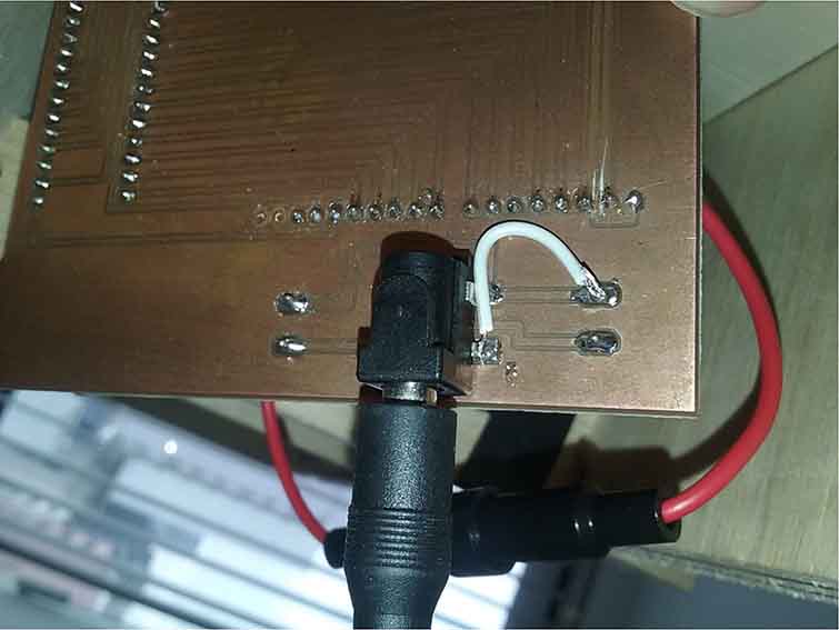
Fixing a connection issue:
I had to solder a cable to connect GND from the DC Power Jack with GND of the terminal because when I connect the power supply the energy doesn't flow. Before that I use a multimeter to check the connection between the GND pins of the power jack that's why I just connect one GND pin of the dc power jack because I tough they were connected internally but after I realized about that mistake Alex explain me when I connect the power supply the GND pin is disconnected internally with the other GND pin.
Machine control
GRBL is a firmware for arduino boards(uno,nano,Duemillanove) that controls stepper motors and spindles/lasers. Because GRBL arduino boards you just hook it up to a free usb port. I found this link with information about how to install the software.
- Download the latest grbl sourcecode as .zip from this link.
- Open the grbl .zip and navigate to a folder simply called "grbl".
- Extract the folder to a known place and open the arduino ide.
- In the arduino ide, navigate to sketch>include library> add .ZIP library.
- Navigate to the grbl folder and click ok. Grbl is now installed as a arduino library.
- Navigate to file>example>grbl>grblupload. A new sketch will open with instructions on how to flash grbl to your board.
Now with firmware on the board we need to adapt grbl to your specific machine. To communicate with your board you need to open the Arduino IDE serial monitor. You should see a message like this "Grbl x.xj ['$' for help]" if you dont see the message, make sure that your are connected to the correct port and use the baudrate of 115200. Type "$$" and a list of commands should appear, like this:
- $100=250.000 (x, step/mm)
- $101=250.000 (y, step/mm)
- $102=3200.000 (z, step/mm)
- $110=500.000 (x max rate, mm/min)
- $111=500.000 (y max rate, mm/min)
- $112=500.000 (z max rate, mm/min)
- $120=10.000 (x accel, mm/sec^2)
- $121=10.000 (y accel, mm/sec^2)
- $122=10.000 (z accel, mm/sec^2)
- $130=200.000 (x max travel, mm)
- $131=200.000 (y max travel, mm)
- $132=200.000 (z max travel, mm)
To save time we are using the same configuration made by the students of the last year.
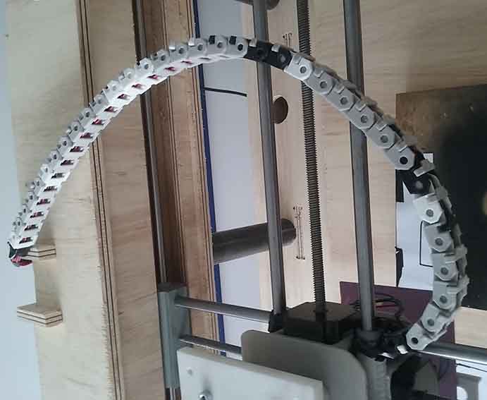
Cable chain
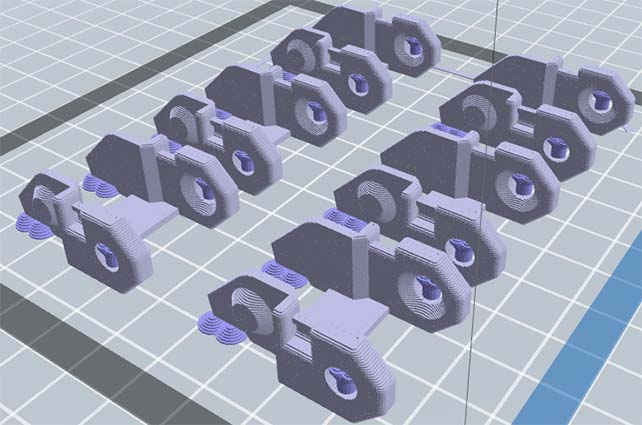
We download this file from Thingiverse to support the cables and also give mobility we decided to 3d print the cable chain and add more digital fabrication processes in relationship with the other pieces.
Links: are one modules which are repeated until form a chain inserting pins from one side into the other side holes until reach the chain shape.
- Type: dendritic
- Base diameter: 6 mm
- Post diameter: 3mm
- Base tall: 3mm
- Auto support.
- Resolution: Low (Faster)
- Layer height: 0.3mm
- Perimeter structure: 2
- Superior and bottom solid layers: 2
- Infill: 10%
- Pattern density: Line
- Speed:80nm/s
- Trajectory speed:: 100mn/s
- Extruder temperature: 220C
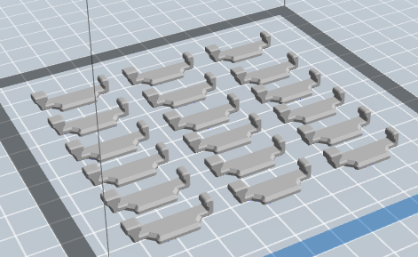
Locks: are modules that we use them to secure the cables.
- Resolution: Low (Faster)
- Layer height: 0.3mm
- Perimeter structure: 2
- Superior and bottom solid layers: 2
- Infill: 10%
- Pattern density: line
- Speed:80nm/s
- Trajectory speed:: 100mn/s
- Extruder temperature: 220C
Final result:
Check the video of the machine drawing
Conclusions:
We didn't assembly all the parts in a digital file so we had a mistake in the dimensions of the rods and we realized about that we assembly all the parts and review the right dimensions of the rods also we check in the real model.
Improving a previous development was a good decision because we safe time and also we contribute to all the effort made previously by the students of the previous years.
Always is better to review the datasheet of the components to know the current and voltage necessary and also to know some details about how is working.
PLA is a flexible material so will be better if we use steel for the bearing system but to understand the principles of the machine I think work very well.