Inputs
INPUT DEVICES
This is the content we had covered this week:
W10 - Inputs
- Input Types
- Communication
Assignment
-
Group assignment: Probe an input device’s analog levels and digital signals
-
Individual assignment: measure something: add a sensor to a microcontroller board that you have designed and read it
This week we’ve digged into understanding inputs and talking about many sensors.
HOW TO USE INPUTS
Although I’ve used different inputs in the past, I wanted to gain a deeper insight of the “sensing” rather than the sensors itself. Here is my visual summary:
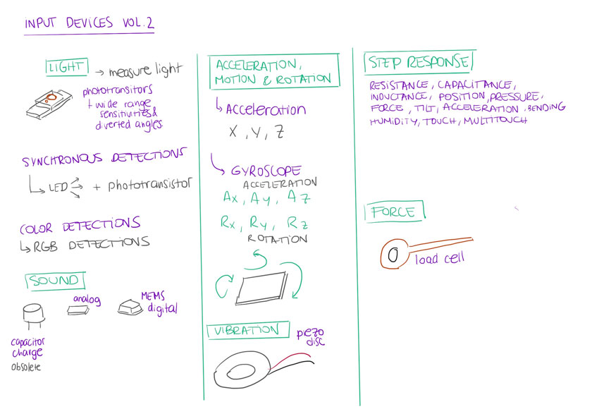
INPUTS 101
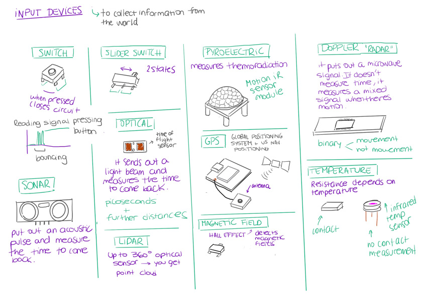
"Diagram showing different inputs and its features."
"iDagram showing different inputs and its features."
DIGITAL VS ANALOG
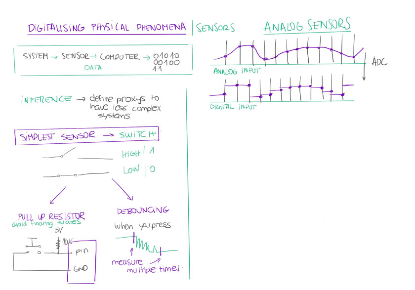
"Diagram showing how sensing physical phenomena works + Analog to digital signal."
GROUP ASSIGNMENT
For the group assignment I thought on how I could contribute to the group. Besides the flex sensors and their readings I decided to resucite a documentation I created almost three years ago that it’s not online anymore.
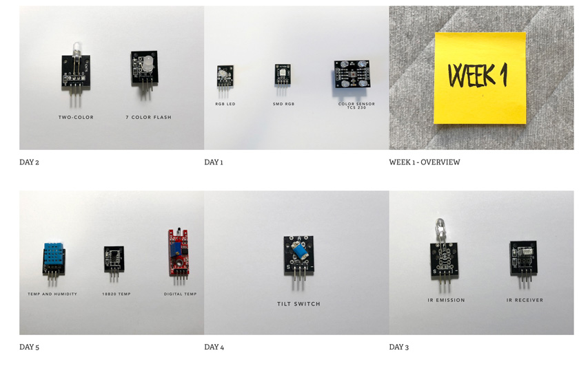
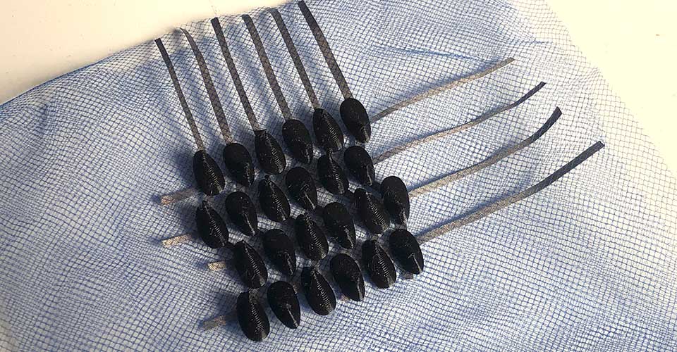
"Image showing all the sensors tested on week 1 of research"
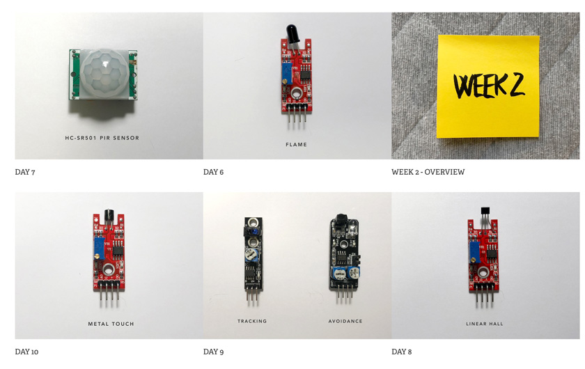
"Image showing all the sensors tested on week 2 of research"
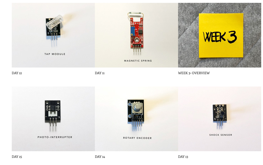
"Image showing all the sensors tested on week 3 of research."
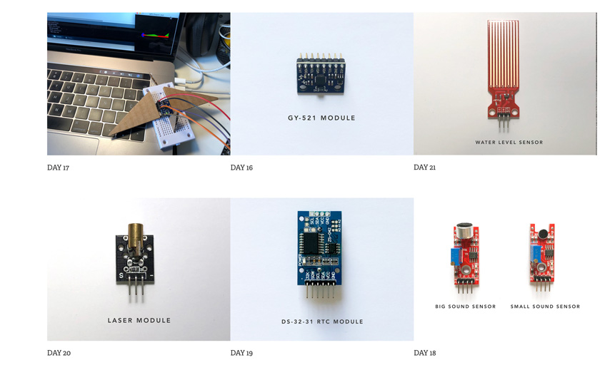
"Image showing all the sensors tested on week 4 of research."
WHAT WENT WELL
Variety: I’m sharing as many sensors as I’ve worked with and I think it can be helpful for others.
Back online: I’m happy that this information is back online.
WHAT COULD BE BETTER
I got myself more that I can chew:Even though it’s something that I created a bit ago, it needed a lot of img compression, organization and planning.
More documentation: I wish I had more equipment when I did this documentation to complement it
INDIVIDUAL ASSIGNMENT
HOW TO MEASURE SOMETHING
SQUEEZING A CONDUCTIVE POMPOM | ATTINY 45 CIRCUIT
I was very excited to think of more applications for my flexible vinyl cut ATtiny 45 circuit. I remember creating a conductive pompom a while ago during a pompom workshop, but I didn’t get the chance to play with it before, so here I go!
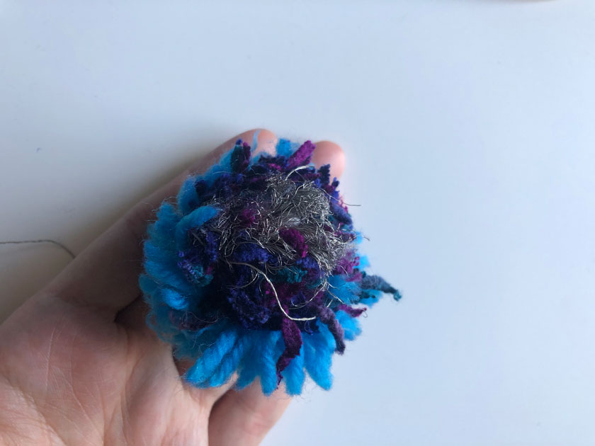
"Pompom made during a workshop held by Sam Topley."
STEP 1: TEST CAPACITANCE ON LILYPAD’S PAD
I’ve never used capacitance on an ATtiny before, and as the ATtiny doesn’t have Serial, I wanted to try the pompom first in a debuggable setup. That’s why I started with the Lilypad.
To do so I did some quick research, and the best resource I found it’s this one below:
Fabric Piano using capacitive sensing
Capacitive sensing code for Lilypad
Additional research: Kokabant site
"Lilypad programmed for capacitive sensing on one sewable pad showing values on the Serial Monitor."
int pompom = A2;               // name of the first sensor key
int touchValue;

void setup() {
  // put your setup code here, to run once:

  pinMode(pompom, INPUT);   // set key1 to be an input
  Serial.begin(9600);


}

void loop() {
  // put your main code here, to run repeatedly:

    touchValue = readCapacitivePin(pompom); // read the touch sensor value
    Serial.println(touchValue);           // send touchValue to the computer
  1delay(100);

}
STEP 2: TEST CONDUCTIVE POMPOM’S CAPACITANCE RANGE
Using the same code I attached the conductive pompom to the capactive Lilypad’s pad. As it can be seen the capacitance range varies slightly.
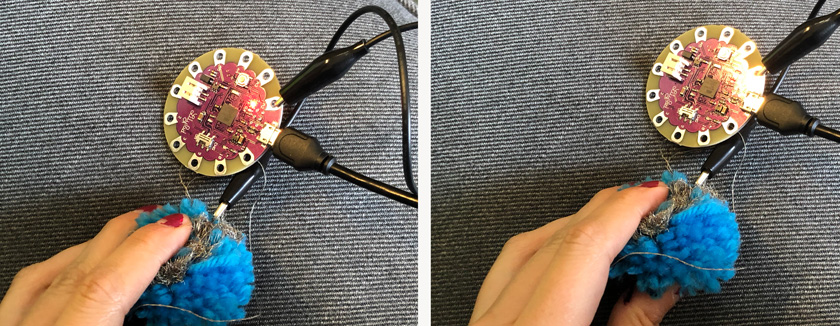
"LEFT: Lilypad + Capacitive Pompom. RIGHT: Squeesing Capacitive pompom."
STEP 3: ADAPTING THE CODE TO ATTINY 45
After reading all the documentation and getting familiar with the concepts I wrote this code. What I wanted to achieve was mapping the capacitance of the touch value to the intensity of an LED. To do that I mapped the range of the touch sensing (from 0 to 7) to the range of an LED using pwm (0, 255).
TAKE 1: NOT WORKING. THE RANGE WASN’T RIGHT.
ledIntensity= map(touchValue,1,7,0,255);
    analogWrite(led, ledIntensity);
TAKE 2: PROGRAMMING AGAIN ATTINY WITH NEW RANGE & IT WORKS YAY!
The first time the capacitive range I defined for the ATtiny wasn’t working very smoothly as it was too sensitive. Therefore I changed the range and this time it worked really smoothly.
int pompom = 3;               // name of the first sensor key
int touchValue;
int led= 0;
int ledIntensity;


void setup() {
  // put your setup code here, to run once:

  pinMode(pompom, INPUT);   // set key1 to be an input
  pinMode(led, INPUT);
  //Serial.begin(9600);


}

void loop() {
  // put your main code here, to run repeatedly:

    touchValue = readCapacitivePin(pompom); // read the touch sensor value
    //Serial.println(touchValue);           // send touchValue to the computer
    delay(100);

    ledIntensity= map(touchValue,1,12,0,255);
    analogWrite(led, ledIntensity);


}
Download Pompom Touch + Dimming LED ATTINY Code
STEP 4: STANDALONE SYSTEM + LI-PO BATTERY
My goal was to achieve a standalone system and that’s why I needed a power supply that was portable. After some faulty/ discharged Li-po batteries & having to enlarge/ fix some pads, it seemed to work.
TEMPORARY SETUP
The first setup was using the Li-po battery connected through some aligator clips. Proof of concept, CHECK!
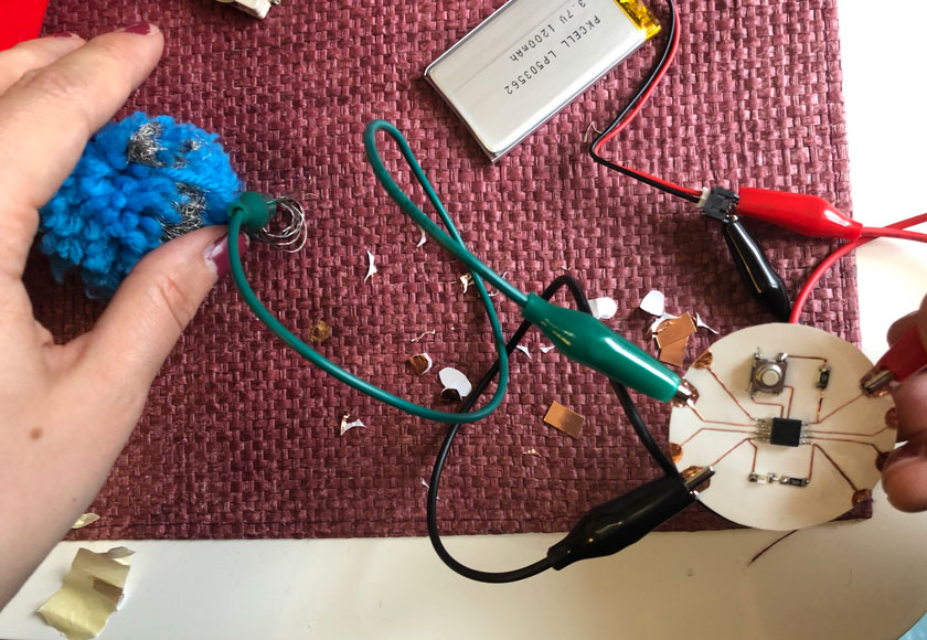
"Testing Li-po battery with Attiny 45 circuit + conductive pompom"
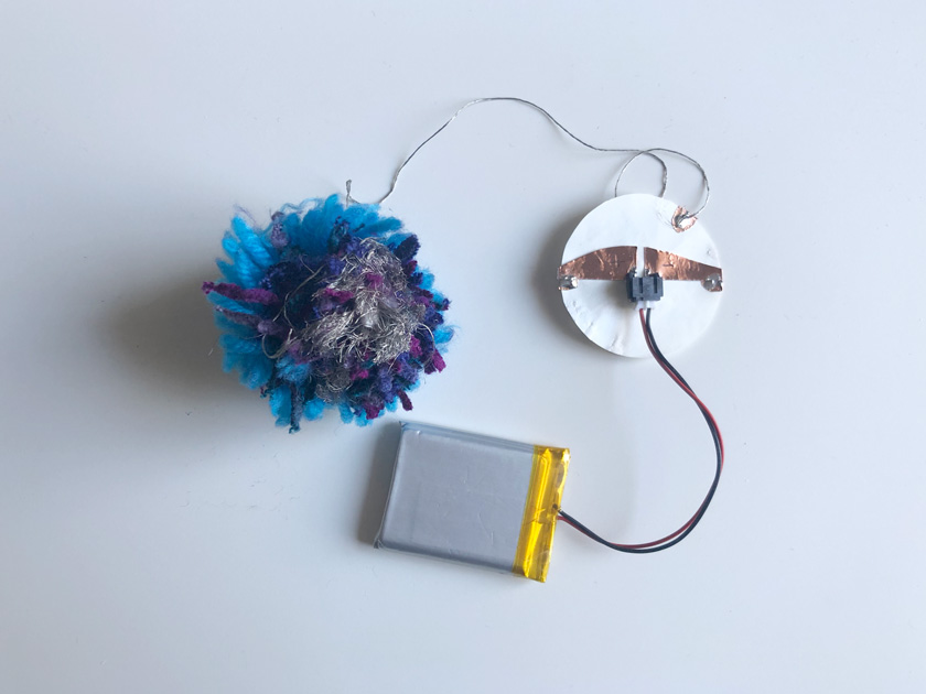
PERMANENT SETUP + BATTERY SOCKET + SOLDERING SENSOR
As I wanted a permanent setup that allowed me to remove the battery for charging, I decided to add a Li-po battery socket to my board and add a back pad for soldering the sensor.
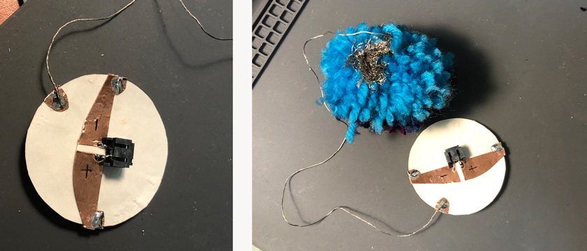
"LEFT: Battery pads + Li-po socket on the back of the ATtiny circuit. RIGHT: battery socket + sensor soldered to the back of the board."
STEP 5: FINAL SHOTS
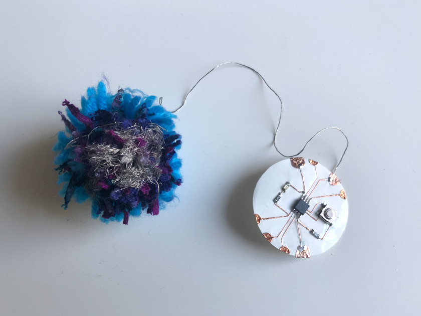
"Conductive pompom + ATTiny 45 vinyl cut circuit."
"Conductive pompom + ATTiny 45 vinyl cut circuit on the back."
"Capacitive pompom + ATTiny 45 circuit (dimmable LED)+ Li-po battery"
HERO SHOT
"Capacitive pompom + ATTiny 45 circuit (dimmable LED)+ Li-po battery. Hero shot."
WHAT WENT WELL
Had fun: I particularly enjoy this project. It was really fun to work with this squeezy sensor
Felt personal: Crafty projects always feel more experimental to me.
WHAT COULD BE BETTER
Suffered a bit: I had some issues with my circuit as it’s becoming very delicate. Every time I need to program it using Arduino ISP I need to plug many aligator clips and some pads started to break.
I will need a new circuit: This circuit my be coming to an end. If I wish to keep working on flexible circuits I’ll need to develop a new one with more pins, try to avoid ISP programming and more durability.
SPOOKY TOUCH MATRIX
As a disclaimer before starting with this sensor. I’ve already worked with a touch matrix in the past, but never in such a high resolution (meaning more analog inputs needed) and on a flexible setup (trickier in any aspect.).
Carla’s old experiments using touch matrix
Fabacademy’s project inspiration
7x7 Matrix using Kapton & copper
The main explanation taken from this resource on how I plan to develop this sensor is this one that follows:
“A simple pressure sensor matrix made from two Kapton film sheets with 7×7 copper tape traces and a piece of Velostat or Eeonyx piezoresistive material in between. parsing through this grid by switching individual rows/columns to be HIGH, LOW or INPUT (high impedance) to detect location and pressure.”
In my case it won’t be kapton & copper. It’s silver conductive tape and 3d printed tule. But the principle on having rows/columns and high impedance is the same.
STEP 0: WHAT DO I NEED?
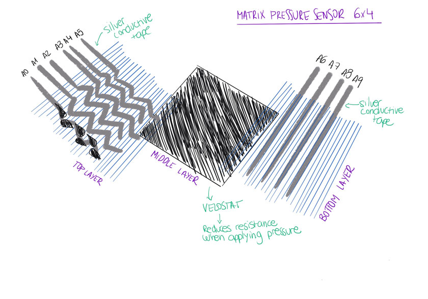
"Sketch showing all the elements that I need to build my sensor."
I need to understand this better rather than following instructions:
Kobakant explanation of how the matrix works
In this case I’ll be using one concept that Oscar explained last week, how to translate analog –> digital (using the ADC =Analog Digital Converter).
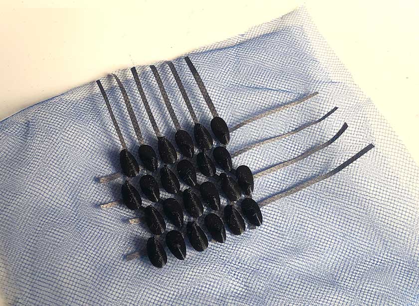
STEP 1: CREATE MATRIX TRACKS. (6X4)
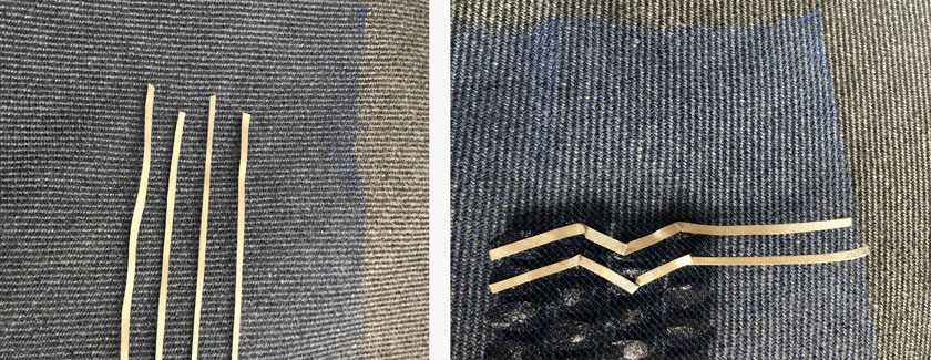
"LEFT: conductive silver tape traces on top tule (straight traces bottom layer). RIGHT: 3D printed tule with conductive tape traces underneath (zig-zag traces top layer)."
TOP LAYER DETAIL
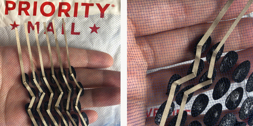
"LEFT: Top layer. RIGHT: Zoomed detaile zig-zag traces top later"
STEP 3: ALIGNMENT TEST
"Top and bottom layer already aligning the matrix,"
STEP 4: ADDING & TESTING VELOSTAT LAYER
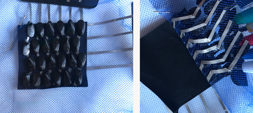
"LEFT: Matrix Layers on on top of the other. RIGHT: Matrix layers revealing velostat and cross conductive materials."
"Testing change in resistance when pressing matrix using multimeter."
STEP 5: CONNECT MATRIX TO MICRONTROLLER
I need a microcontroller that would offer me at least 10 Analog Input pins in this particular case. I decided to use Arduino Leonardo ( ATMega 32u4), in this case, to be able to properly debug the matrix and its readings as with so many tracks in place, it could be an escalating error-prone project.
If it works I might mill one board for the output project. I checked the invetory and there’re no ATMega 32u4 which means I’d need another option for the next phase.
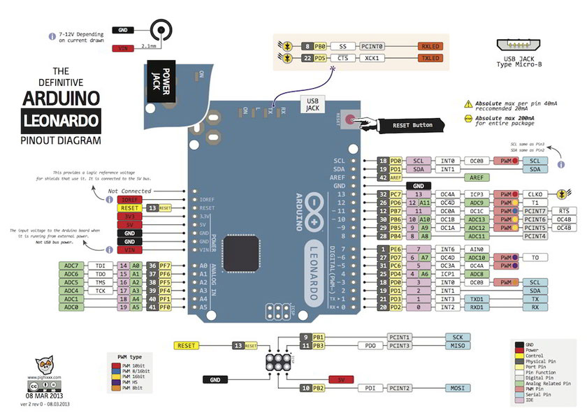
"Arduino Leonardo pinout drawing."
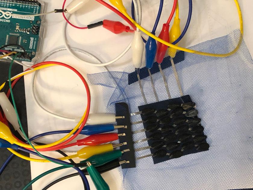
"Arduino Leonardo Analog Pins connected to the Matrix. Top Layer 6 tracks (A0-A5 corresponding to Analog Pins 0 to 5). Bottom Layer 4 Tracks A8-A11 corresponding to digital pins 8,9,10 and 12."
From my past experience working with this kind of sensor I already knew that I had to filter the readings within a range to know if the point was pressed or not. This is the piece of code that I use to print only the number of the point of the matrix that I’m pressing. See video below.
 for(int i=0; i<lengthArray; i++){
      //Serial.print(incomingValues[i]);
      if(incomingValues[i]<100){
        Serial.print(i+1);
      }
"Testing Matrix using Arduino Leoardo + Serial Monitor. The number that appears is the number of the element within the array of touch points."
STEP 6: TEST MATRIX
As I had many more inputs than in my past experiments I felt the need to organize the output of the serial monitor visually. That’s why I’m showing a 6x4 array of numbers corresponding to the physical matrix.
"Testing Matrix using Arduino Leoardo + Serial Monitor. The number that appears is the number of the element within the array of touch points."
STEP 7: DEBUG MATRIX + READABLE SERIAL MONITOR OUTPUT
I tweaked a bit more the code, and this is the final version:
"Testing Matrix using Arduino Leoardo + Serial Monitor. The number that appears is the number of the element within the array of touch points."
Download Matrix Code Matrix Array Display
HERO SHOT
WHAT WENT WELL
Risky business: I always have fun when I have a challenge and this was a good challenge for this week. I knew it was possible to do but not sure if I was going to be able to achieve it.
Learning more about something I thought I knew: I’m glad to revisit something I’ve already worked in the past. This time everything makes more sense.
WHAT COULD BE BETTER
Tricky setup again:When working with experimental soft circuits there are so many things that can go wrong.
New circuit: I should be developing a new circuit for this project that doesn’t require so many alligator clips and the Arduino Leonardo.
BONUS TRACK | NEW BOARD + TILT SENSOR
After Edu’s suggestion of having a sensor embedded into a board I’ve designed I decided to try to challenge myself on repurposing one of the boards I’ve designed for my final project that I had a spare to reduce waste. You’ll find the schematics on final project development. Board Design
My idea was to see what I had available with the current circuit and I choose a sensor that I hadn’t used before and to maximize the potential of so many pins one next to another so I created a small array of RG Leds. It was a really fun exercice
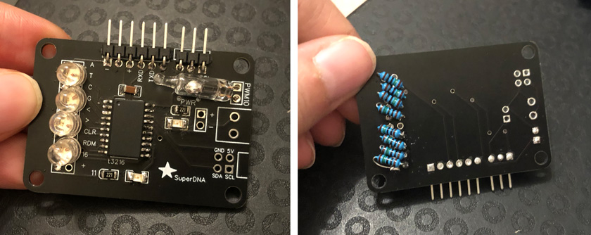
"SuperDNA board repurposed with a Tilt Sensor."
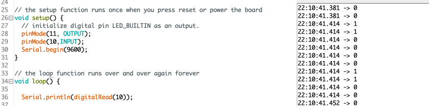
"LEFT: Arduino code to read Arduino signal RIGHT: Serial reading titl sensor signal."
"Tilt sensor switching LEDs state when moving sensor."
"RED-GREEN-RED-GREEN... Tilt sensor."