3. Computer controlled cutting
Finally: we get to work with machines! Great 😄
Group assignment: testing kerf & speed/power settings
We already use this laser cutter for around 5 years now. We also have a book with the speed/power settings for lots of the materials used here in the lab.
We already use this laser cutter for around 5 years now. We also have a book with the speed/power settings for lots of the materials used here in the lab.
- Using the laser: workflow in 2 parts
1. Lightburn software
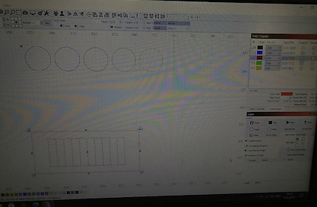
For controlling our laser and sending files to it we use Lightburn software. This software has basic drawing abilities, so you could make a small design directly in here. It also allows you to import DXF, PDF, AI,… files. In it you can give power/speed settings to different colors.

In the cuts/layers panel you can select a color and select a mode for it. On the bottom of the screen you can select the library panel to choose from the already available materials and assign those settings to the selected layer. You can also set the power and speed for this color in the layer panel manually, if it is not yet in the library. If you double-click on the colored layer, you get a popup window with more extra parameters and settings you can adjust. Once all settings are correct you can choose how to send the file to the laser machine. In the laser panel you can choose a job origin and what parts you want to send to the laser.
![])https://gitlab.fabcloud.org/academany/fabacademy/2021/labs/barcelona/students/kurt-vanhoutte/-/raw/master/docs/images/week03/lightburn2.jpg)
2. On the machine control panel
After you switch on the machine it will go through a startup and homing sequence. On the control panel you can move and manage the laser.

first you have to move the laser bed back up with the Z+ button You can put your material on the bed Move the laserhead around with X and Y buttons until it is in the corner you want to start. Use the origin button to set the starting point. Use the file button to select the file you want from the filelist. Confirm with enter. You can now use the frame button to move along the contour of your design and check if it fits your material.
Next you need to focus the laser. In our machine the laserhead needs to be 6mm above the material surface. We use a 6mm piece of wood to adjust the height. Using the 2 screws you can loosen the nozzle and move it up/down. Place the focus piece on the material under the nozzle. And let the nozzle rest on the focus piece. Now tighten the screws again.

Almost ready to do some cutting. Close the lid of the machine and turn on the exhaust-system. Now on the control panel press the start/pause button.

3. Test parts
For this exercise we wanted to do the tests again on 2 materials we want to use to make the press-fit pieces in.
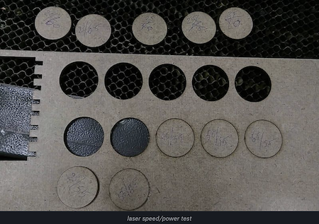
First we made a drawing of some circles and rectangles to test different power and speed settings.
For controlling our laser and sending files to it we use Lightburn software, in it you can give power/speed settings to different colors. For most new materials I guess the power/speed combo and make 5 to 10 different combinations or variations around it. All have a different color and each circle in the drawing gets a different color. That way you cut all circles and can check to see which cut was the best or cleanest
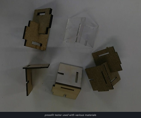
For the kerf tests we made a simple parametric part in Fusion360, to be able to test different kerf compensation and materials easily.
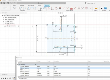
Design file: pressfit tester in Fusion360 format Design file: pressfit tester in STEP format
Hardboard 2.75mm thickness, is a very nice waste material from packaging sheets of PETG. So we want to use it by way of upcycling it.
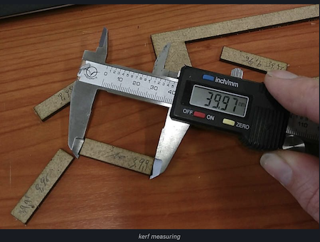
Speed/power test : 35/55 Kerf tests : 0.1 mm Design file: hardboard test file in DXF format
Kraftplex 1.5mm
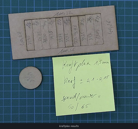
Speed/power : 50/65 Kerf : 0.1 - 0.15 mm Design file: kraftplex test file in DXF format
Different material tests with press fit tester piece.
Vinyl cutting
1. The machine: Roland Stika SV-12
Getting ready to cut now. I inserted a roll of material into the vinyl cutter. By turning the knob you can decide were you want the machine to start cutting. When you’ve decided you need to inform the machine by setting the origin by pressing the button.
Don’t forget to adjust the lever on the right depending on the thickness of your vinyl. Make sure the materiaal is stuck nicely, otherwise you’ll end up having dancing vinyl while cutting.


If it’s a new material or a different material than last time, you need to do a test cut by pressing the on/off button for a few seconds. The machine will cut a test cross and a square. By doing this you test the pressure and speed settings. The goal is to let it cut this and then see if you can easily weed out a part of this test. If that works ok, you’re good to go. If it’s not, you can increase the pressure on the machine.


Adjusting the pressure can be done by turning the shaft where you place the cutting knive. You can turn the bottom half in order to bring the knife up (less pressure) or down (more pressure).


2. The octopus
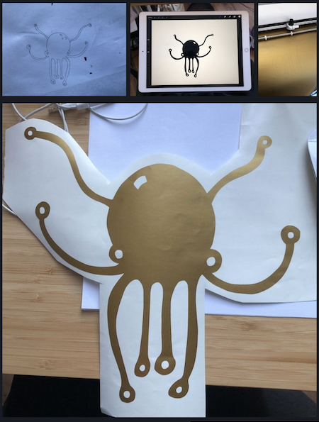
Drawing is something I enjoy a lot. I draw everywhere and whenever I can, or at least: I doodle everywhere. So for this assignment I decided to transform one of the doodles from last week in to a sticker. As octopuses are super cool (they have nine brains, did you know?), I decided to go for extra brain power and went with the octopus.
I drew on a piece of paper, hence the ink stains (<3). The next step involved tracing the image of the paper drawing on my iPad pro in ProCreate, leaving me with a PNG file. Of course the machine needs a vector file, but PNG tracing in Illustrator gives you super smooth results. After some finishing touches, the octopus was cut directly from Illustrator using a Roland plugin. At home I have the Roland SV-12, which is a smaller vinyl cutter but you can cut pieces up to 28cm by 1m so more than big enough for most things. After peeling off the exces vinyl, I was left with a very cute golden octopus. Now to give him a new home…
Design file: Octopus
Parametric construction kit
Laser cutters are a lot of fun to work with, but there are quite a few things to keep in mind when designing for them. For this assignment we had to develop a parametric construction kit. I did a bit of research to what students developed in the past year, which are a lot of triangles and squares. I get it, it’s easy to draw and the assignment is finished pretty quickly. I decided to go a step further, which is why I’m still in the testing phase instead of having a completely finished product. But it already works, it just needs some more finetuning.
Here it comes: I want to make a parametric herbivore dinosaur construction kit. Based on the image flipbooks I enjoyed so much as a child (and still do). Simply put: lots of different heads, tales, spikes, skins, … so you can construct different types of dinosaurs and create new ones along the way. Or even go beyond and make some alien dinosaurs: everything is possible.
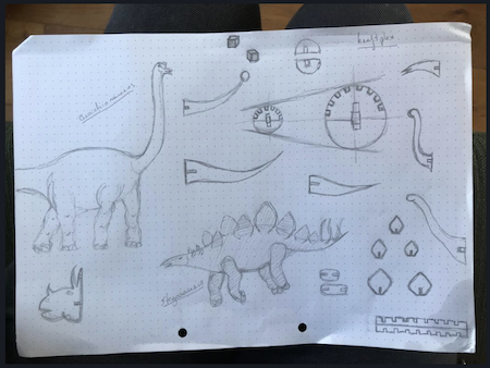
First things first, I read about herbivore dinosaurs and drew some of them.
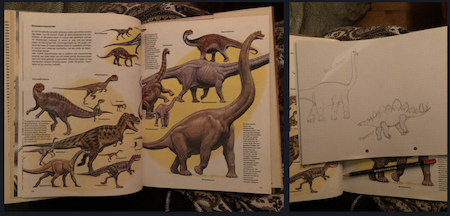
It occurred to me that there are not too many different shapes a dinosaur takes. Most of them have a pretty similar form when it comes to their bellies. The head and tails are the parts that differ te most. Some are pretty short and some are longer. Having an idea about the different forms, I started designing components.
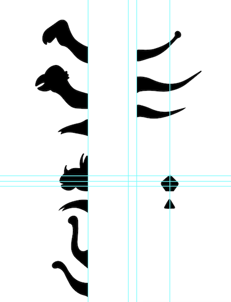
Having all these different shapes and forms drawn by hand, it is time to redraw them digitally and make them parametric. As I haven’t made something truly parametric before, the biggest struggle this week was to find the software which suited me best. And I do mean a struggle… I’m used to drawing vectors in Illustrator or Inkscape, but not in software that is used to make technical drawings and models. I looked for alternatives that offered parametric options, but couldn’t find any.
As I wanted the dinosaur parts to keep their shape, I decided to add an extra step and drew them in illustrator first, without the cut outs to stick parts together.
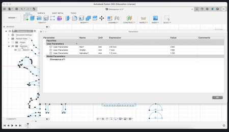
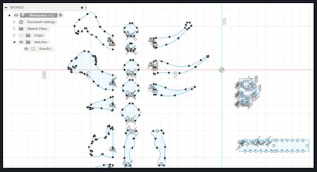
I saved this file as an svg so I could easily import it in Fusion 360 to add the parametric slots to slide the parts together into a 3D dinosaur. Importing an svg is pretty simple, you press insert and select the file you wish to import. With all the parts in place, I moved onto the next step: setting the parameters based on our kerf test we did earlier. So 2,8mm for slots cut in a 3mm material. I also added half a slot so I could mirror the back bone piece in two mirror actions.
 )
)
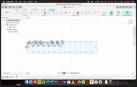
After adding the slots to the parts I ended up having a very messy sketch. For me this is difficult to work with. I’m used to having clean designs and scaling everything by taking into account the different thickness of the materials I want to cut in. However I do understand why parametric design is very useful, I don’t think it’s my cup of tea.
A big part of designing is testing to see whether everything fits and the parts work out as a 3D model as imagined. So the dinosaurs were cut and tested.
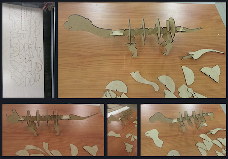
Succes! If you would like to have your own dinosaurs, go right ahead and cut some yourself 🙂
Design file: Dinosaurs in DWG format
The design still needs a bit of finetuning which I will be doing in the next few days. I’m following the Fab Academy next to my full time job so combining everything sometimes asks for a bit more flexible work schedule which I didn’t fully manage this week. And I want to add skin in a flexible layer as well, stuff to think about, luckily it’s dinosaurs! 🦖🦕