Final project
Project slide
Project video
Music is my life. I’m a strong believer that life without music would be a mistake. And how I’ve missed the live performances during these pandemic times… It’s hard to grasp that it’s been almost 15 months without shows, concerts and festivals. I’m hopeful they will return, and in the meantime I’m working on making merch more ecological and DIY!
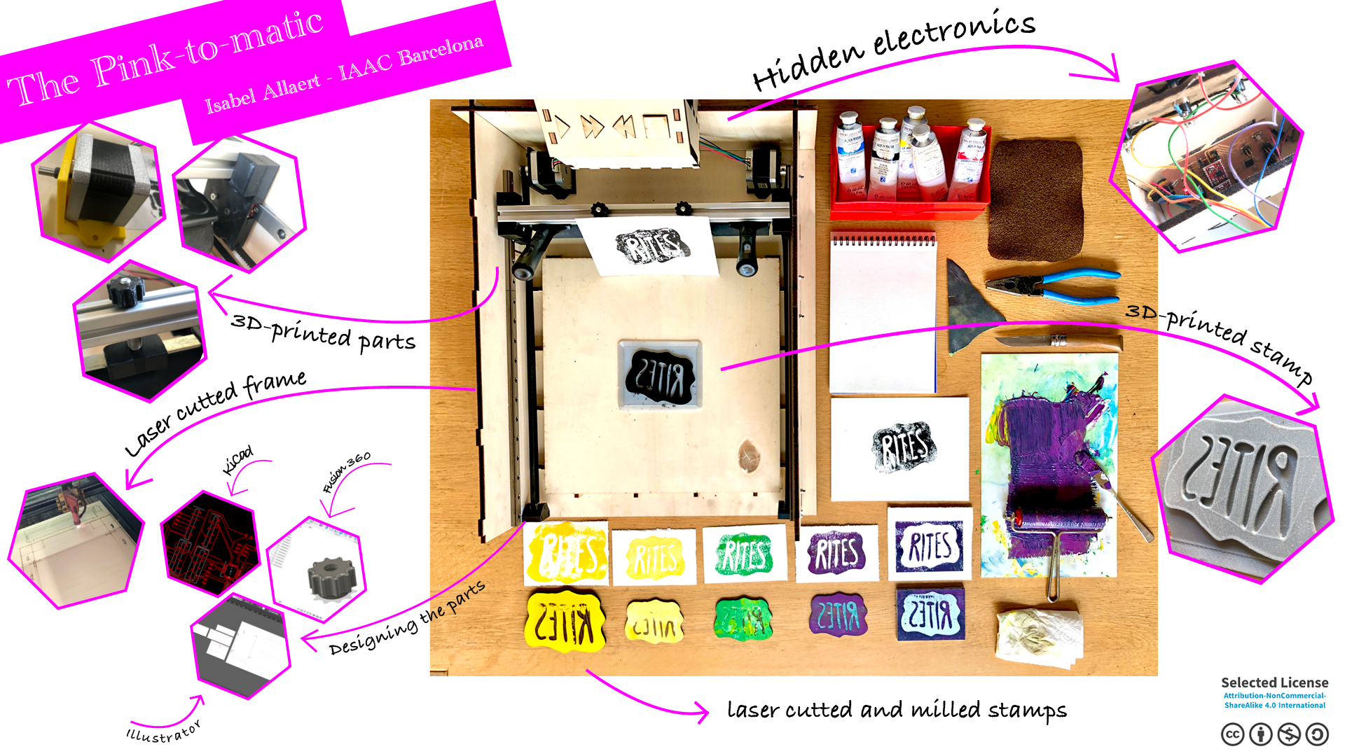
Meet the Pink-to-matic!
Kurt and I will divide the workload for the setup. I will focus on the machine with the timer and Kurt will focus on the device that tells a printer when the print has dried and is ready for pick-up at the merch.

The Pink-to-matic: why and what?
We’re punkers, DIY’s, makers. We make stuff, hands-on. We like to get our hands dirty. We don’t like waste.
Merch is important. It’s the place at a gig where people come together with the band and have a chat. But merch is expensive, it’s pricy for small bands to produce a couple of shirts or tote bags. Or even offer limited prints on their new records. And let’s be honest, pre-printed shirts in bulk aren’t very DIY.
The Pink-to-matic will allow bands to print their own merch, as well as offer DIY printing of their designs on merch stalls. Say I have a shirt and I want to have the logo of a band I just saw on it. The Pink-to-matic would be the solution! For a small fee for ink and the design, your fans can print their own merch. Or, of course, you could print it for them if they ask you to.
To be able to offer a bunch of merch related stuff, we need to be able to print on different surfaces with different materials.

| Substrates | Inputs |
|---|---|
| - 7”, 10” & 12” record covers - stickers to put on the records - CD covers - tote bags - shirts - post cards - … |
- siff for screen printing - linoleum stamp - etch - 3D-printed stamps - laser cutted stamps - … All from different materials such as biobased plastic, eco rubber, … |
How it’s made
The machine itself is a mix of a screen printing machine as well as a printing machine for linoleum prints. The base should therefore be flat and the paper of linoleum should stick properly to the ground plate.
We’re investigating whether we should use a small vacumtable for this or if it’s okay to simply use clamps. Time will tell!

What to do
Building a machine asks for careful planning. There are numerous of things to be done.
Machine parts
- System for screen printing
- System for lino printing
- ground plate
- electronics
- siffs
- stamps
extra options:
- cupboard
- biobased stamps

We made a first division of work based on the different parts. This is were our paths will differ. Kurt will work on the messaging system and I will focus on the machine building itself.
Of course we keep a close eye on each other to make sure that in the end everything works.
So: LEGO prototype first!
LEGO prototype
Thankfully I have a boyfriend with a big LEGO brick collection. It was a very simple choice to build the first prototype using the well known bricks. Half an hour of building, very cool results. I kept coming back to this build all throughout the making of the Pink-to-matic.

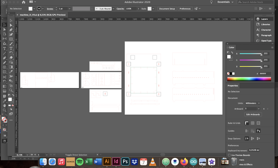
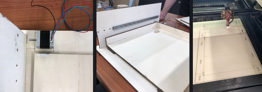
Machine casing
The whole case was designed in Illustrator. The first prototype for this cycle has been laser cutted in poplar triplex, 6 mm thick.
The goal is to mill the final machine in trespa as it’s much more easy to keep clean. At the moment however the prototype is laser cut into poplar triplex.
I started off by simple cutting a 42 x 42 cm base plate. It is supposed to be the ultimate answer anyway, right?
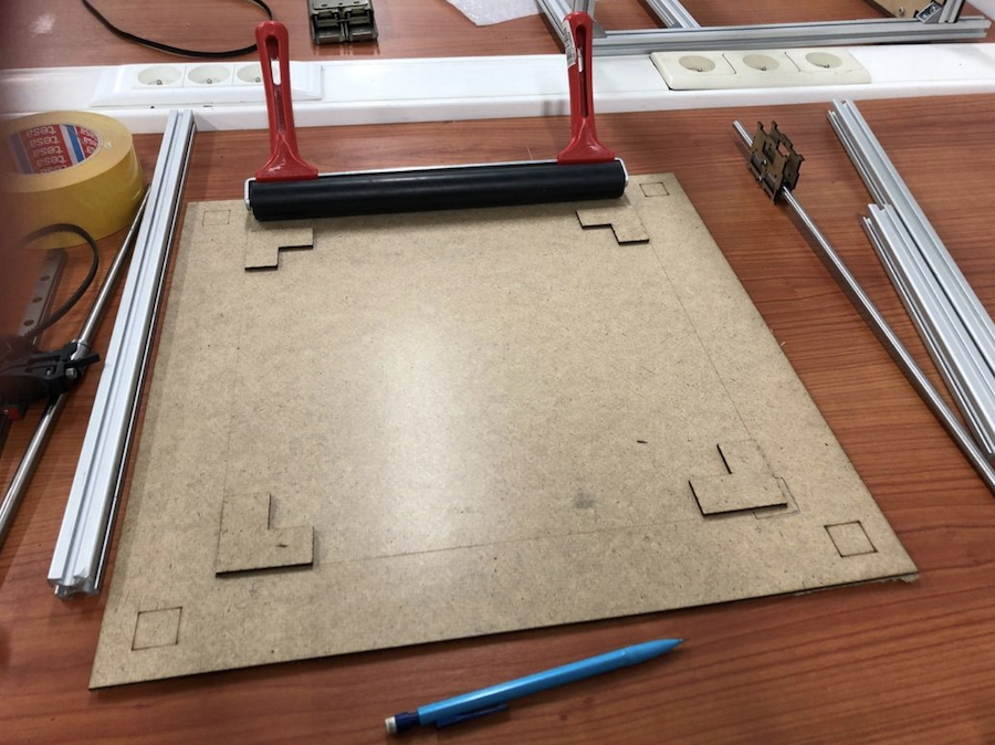
This allowed me to draw on the plate with a pencil where everything needed to be.
The design grew in steps, first the basis and adding the parts needed. Such as the button controller that holds the electronics.
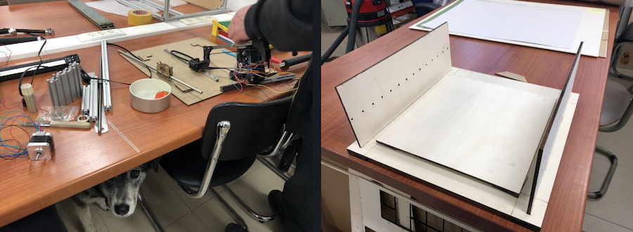
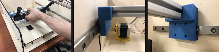
With the machine casing in place, I needed to give it feet.
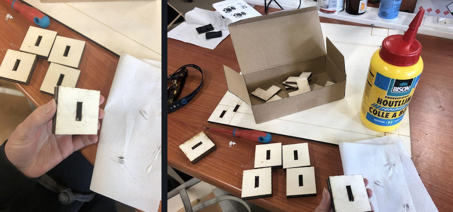
And a controller, sitting on a back panel keeping the two rail holding parts in place.
The ground plate for the stamps rests on a grid, allowing you to change the ground plate to a size you feel comfortable with.
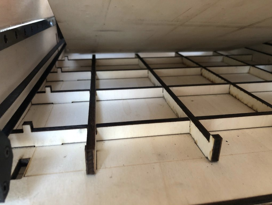
It is my goal to have an engraved (or milled) ground plat in the next version showing guidelines for common paper and vinyl sizes. Always room for improvements :-)
System for press printing with rubber roll
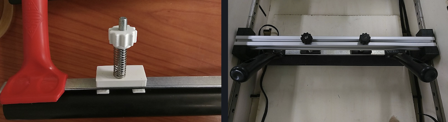
To apply pressure on the stamps in an evenly way, I want to use a rubber roll as they use to ink and press on prints and stamps.
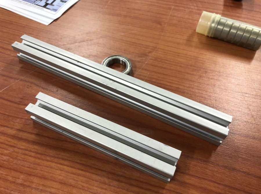
To attach this to the machine, there were a couple of options. The easiest one was to use an old recovered maker beam from one of the printers Kurt build years ago.
You can buy them new at Misumu
The system’s purpose is to roll the paper on the stamp while applying pressure.
As I want to use different types of stamps and materials, it was necessary to make sure that the rubber roll can be adapted and changed in height depending on the used stamp.
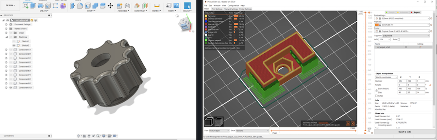
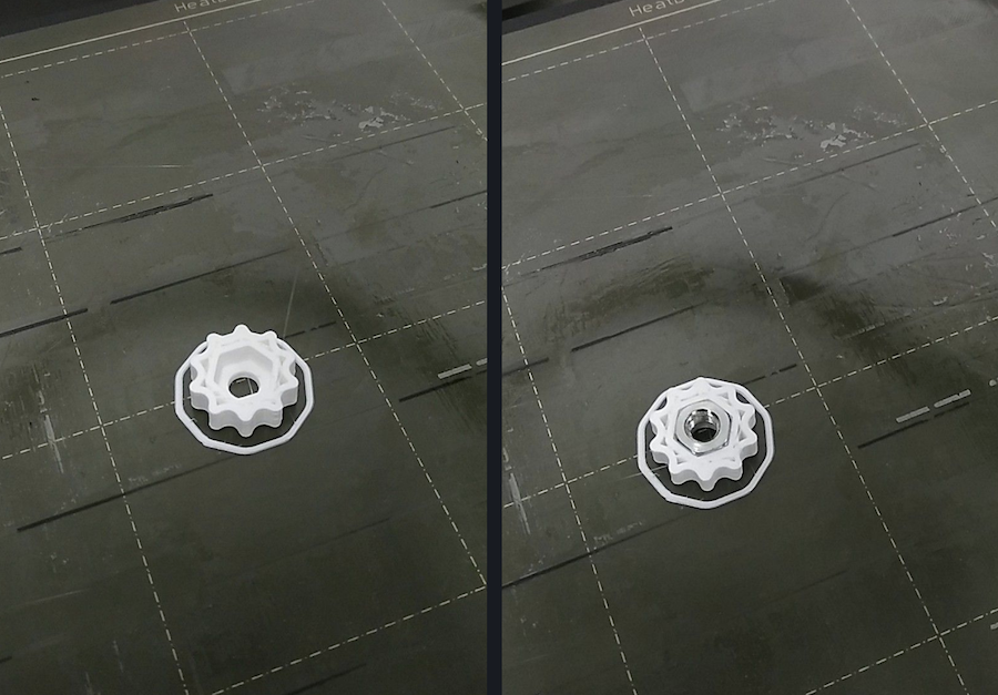
It needed a lift system with springs. The springs were recovered from an old project, the knobs were designed in 3D and printed. A nut is placed in the middle of the part by pausing the printer, adding the nut and continuing to print. This makes sure the nut remains in place after finishing the print. There is a nut in the piece surrounding the metal part of the pressure system as well. Both nuts are needed so that you can move the whole system up and down using a piece of threaded rot together with the spring.
Once attached to the rubber roll, it looks like this. The printed nut allows you to put more or less pressure on the print while printing.
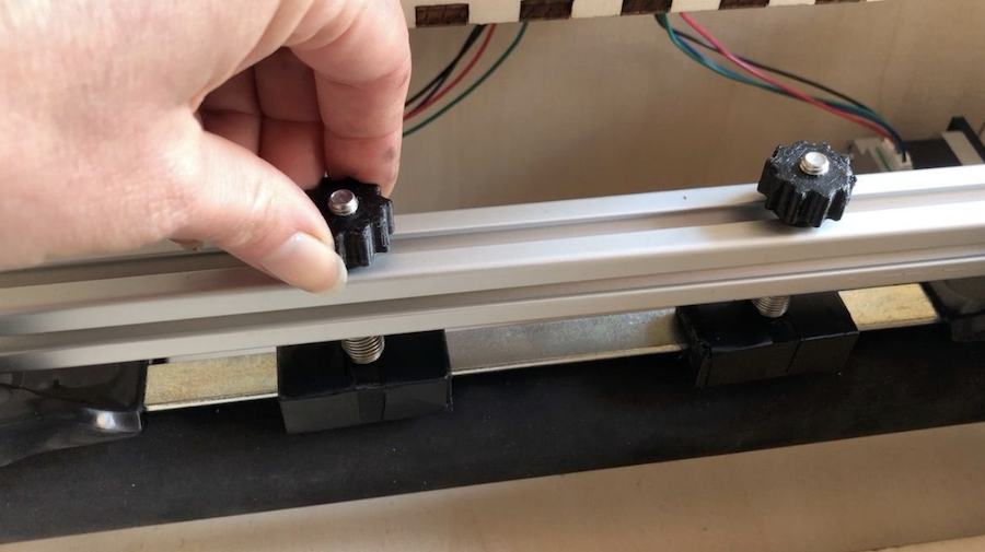
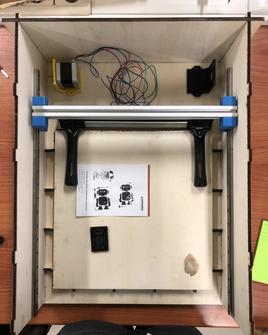
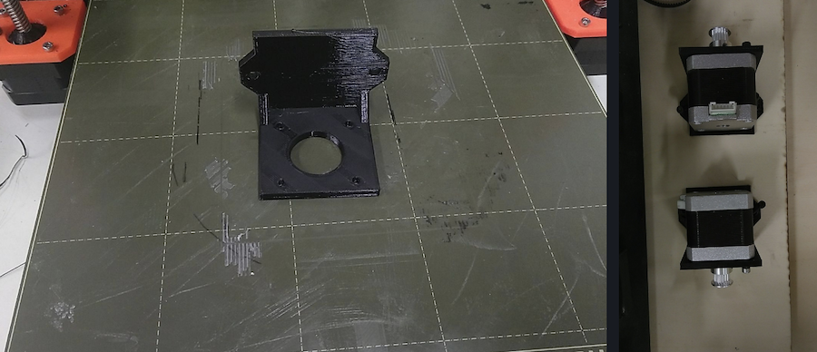
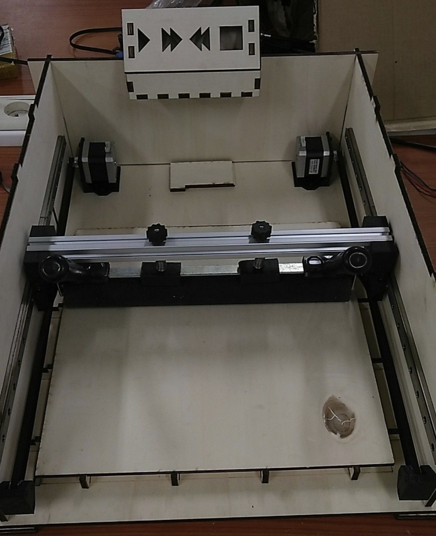
The pressure system moves forward and backwards using two stepper motors that are attached in the back with belts going from one end of the machine to the other. The motors are attached on the ground plate in the back of the casing using 3D-designed and printed parts.
The belts run from the motors to the front of the machine, going through the roll holders onto the belt idlers. Inside the belt idlers there is a bearing to ensure a smooth run.
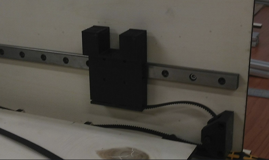
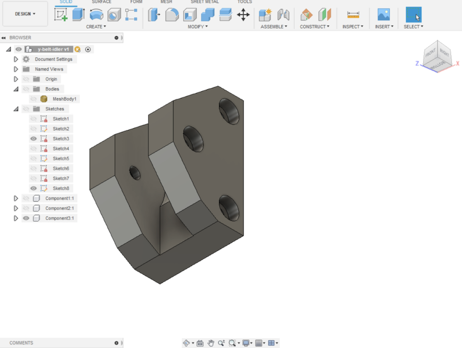
With all the parts coming together, it looks like this. This is the point where I’m getting anxious to start using the machine. So next step: electronics.
Electronics
BOM from KiCad
| Qty | Reference(s) | Value | LibPart | Footprint | Datasheet |
|---|---|---|---|---|---|
| 2 | A1, A2 | Pololu_Breakout_A4988 | Driver_Motor:Pololu_Breakout_A4988 | Module:Pololu_Breakout-16_15.2x20.3mm | https://www.pololu.com/product/2980/pictures |
| 2 | C1, C3 | CAP-10µF | fab:CAP-US1206FAB | fab:fab-C1206FAB | |
| 2 | J1, J3 | NPTC081KFXC-RC | machineboard-rescue:NPTC081KFXC-RC-NPTC081KFXC-RC | NPTC081KFXCRC | https://media.digikey.com/pdf/Data%20Sheets/Sullins%20PDFs/NPxCxx1KFXx-RC%2010487-D.pdf |
| 2 | J2, J4 | NPTC081KFXC-RC-16 | machineboard-rescue:NPTC081KFXC-RC-16-NPTC081KFXC-RC | NPTC081KFXC-RC:NPTC081KFXCRC-16 | https://media.digikey.com/pdf/Data%20Sheets/Sullins%20PDFs/NPxCxx1KFXx-RC%2010487-D.pdf |
| 1 | M1 | LED red | fab:LEDFAB1206 | fab:fab-LED1206FAB | |
| 1 | M2 | FTDI-SMD-HEADER | fab:FTDI-SMD-HEADER | fab:fab-1X06SMD | |
| 2 | M3, M4 | PINHD-1x04-SMD-HEADER | fab:PINHD-1x04-SMD-HEADER | fab:fab-1X04SMD | |
| 1 | M5 | PINHD-1x02-SMD-HEADER | fab:PINHD-1x02-SMD-HEADER | fab:fab-1X02SMD | |
| 6 | M6, M7, M9, M10, M11, M12 | PINHD-1x03-SMD-HEADER | fab:PINHD-1x03-SMD-HEADER | fab:fab-1X03SMD | |
| 1 | M8 | AVRISPSMD | fab:AVRISPSMD | fab:fab-2X03SMD | |
| 1 | R1 | 220 ohm | fab:RES-US1206FAB | fab:fab-R1206FAB | |
| 1 | R2 | 10K | fab:RES-US1206FAB | fab:fab-R1206FAB | |
| 1 | S1 | 6MM_SWITCH6MM_SWITCH | fab:6MM_SWITCH6MM_SWITCH | fab:fab-6MM_SWITCH | |
| 1 | U1 | ATmega328P-AU | MCU_Microchip_ATmega:ATmega328P-AU | Package_QFP:TQFP-32_7x7mm_P0.8mm | http://ww1.microchip.com/downloads/en/DeviceDoc/ATmega328_P%20AVR%20MCU%20with%20picoPower%20Technology%20Data%20Sheet%2040001984A.pdf |
| 1 | U3 | 5V regulator | fab:VOLTAGE-REGULATOR-SOT223 | fab:fab-SOT223 | |
| 1 | Y1 | ECS-CR2-20.00-B-TR | machineboard-rescue:ECS-CR2-20.00-B-TR-ECS-CR2-20.00-B-TR | XTAL_ECS-CR2-20.00-B-TR |
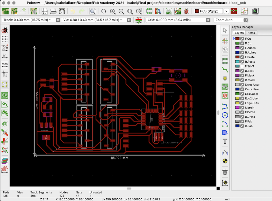
Schematics in KiCad
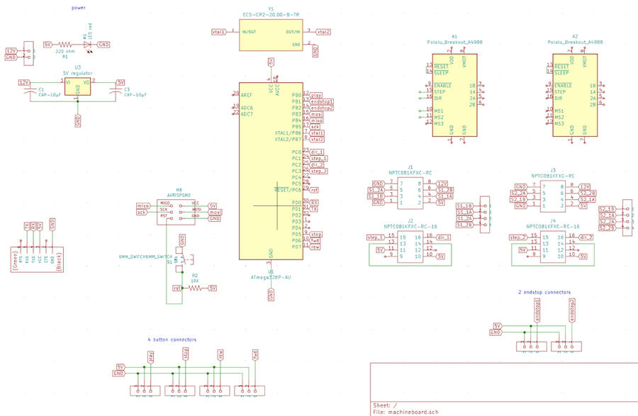
Once everything is correct in the schematics, it’s time for the really hard part: drawing the traces.
It took me a lot of times to get everything right, but I finally managed. Taking the traces into Illustrator, making the png’s, …
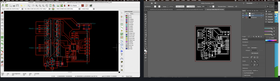
This board was fine, but the milling ended badly. The SRM-20 in the lab does weird things and I was out of lab time.
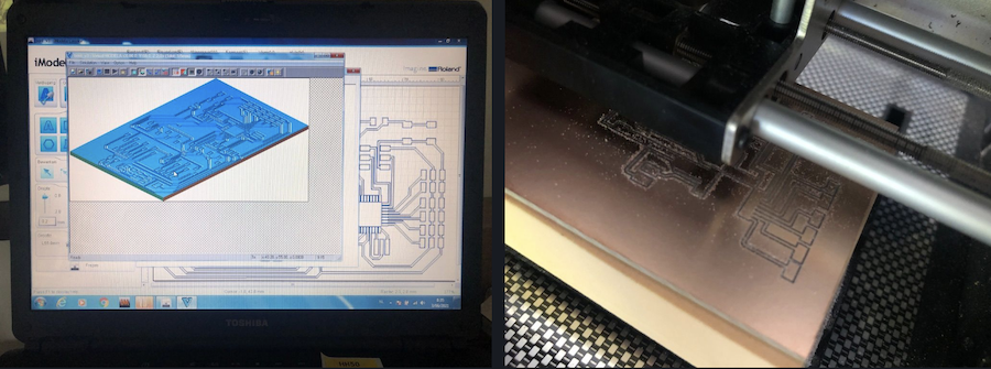
So it was time to see if I could redraw the traces and make the electronics fit the 55 x 85 mm FR2 copper board I have at home to use on the iModela. After a couple of tries I managed!
As the iModela creator software can import svg’s and Illustrator files, there was no need to export a png first. The made up time with skipping this step however, was made up by the board taking forever to mill… The iModela is super precise and I’m always amazed by the results, but you need to be veryyyyyy patient…
17 hours patience…
That’s a lot of patience…
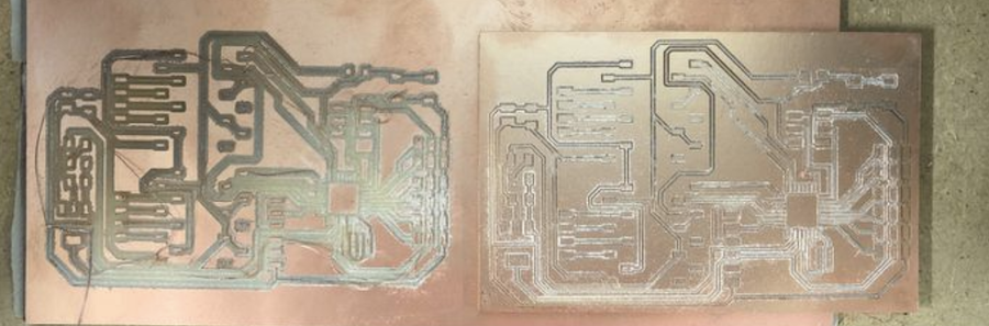
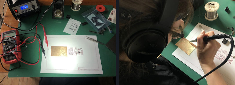
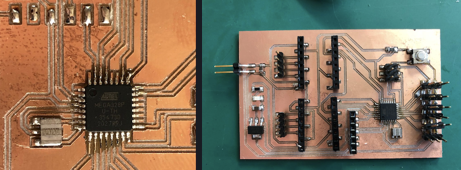
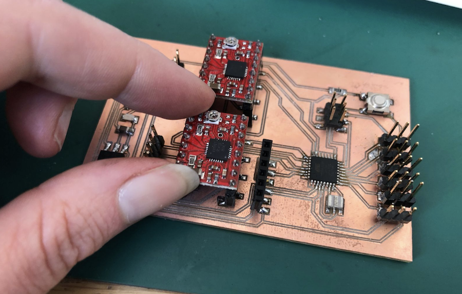
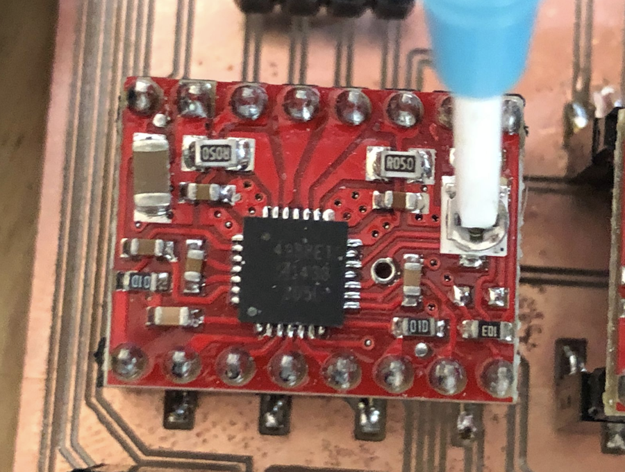
But the board on the left is the one milled on the SRM-20, the one on the right on the iModela. Well worth the wait, don’t you think?
After the long wait, comes the hard part: the soldering. To finish this task properly, I need my noise cancelling headphones and focus. I put on some Nick Cave music, layed out all components, the multimeter and the soldering machine in front of me and got started.
It took a long time, but I managed the soldering! Woop woop!
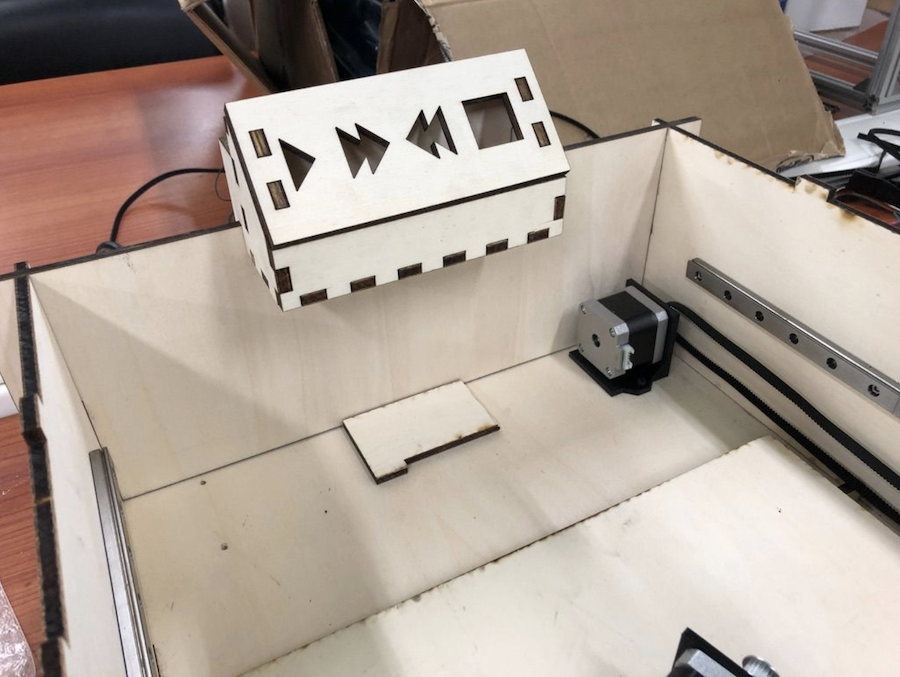
Button controller
The design of the button controller is part of the case design above, but it’s worth a special mention here.
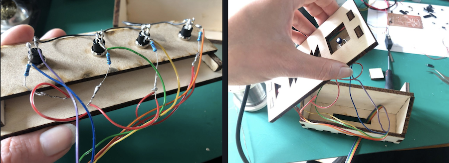
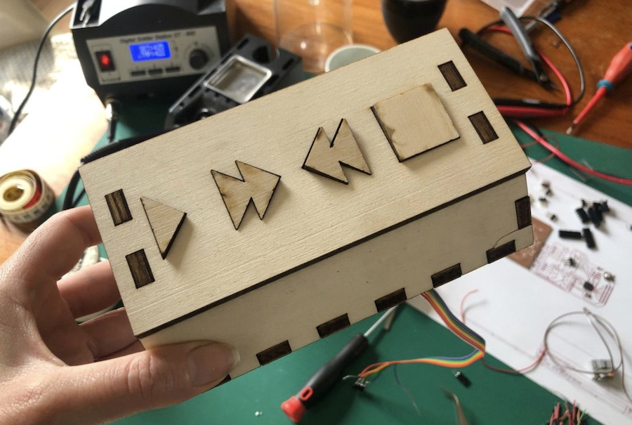
I want the machine to be linked with music, obviously. So I needed a play, forward, rewind and stop button, obviously.
However, they’re not for show. The functions speak for themselves:
Once everything is into place, you press play and the rubber roll goes back and forth. Forward and rewind allow you to go back and forth as needed. And stop, well, this one is the emergency break.
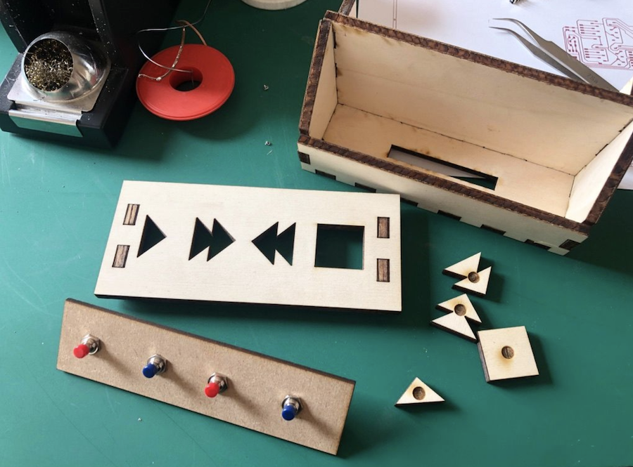
So far only the play button has been programmed, but all buttons have been soldered and installed.
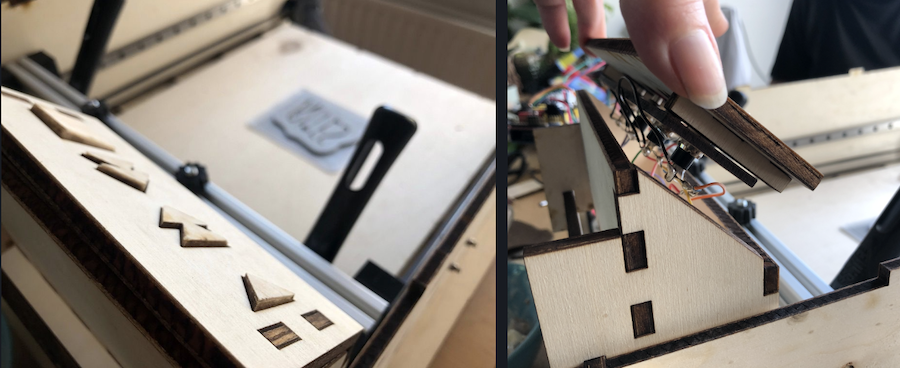
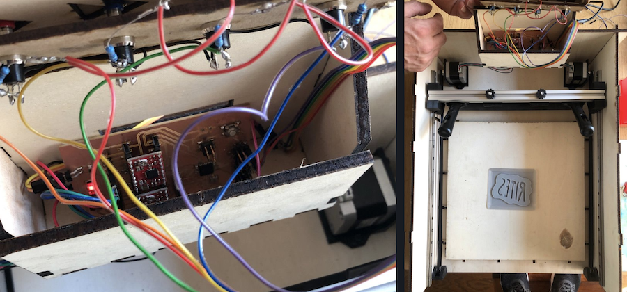
Behind the front panel is an extra hidden panel that holds the buttons. On top of these buttons the poplar knobs have been glued once everything was in place.
The cable work coming from the motors comes inside the control panel via the bottom, the power and usb goes out through the back.
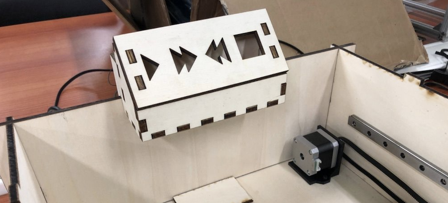
And tada!
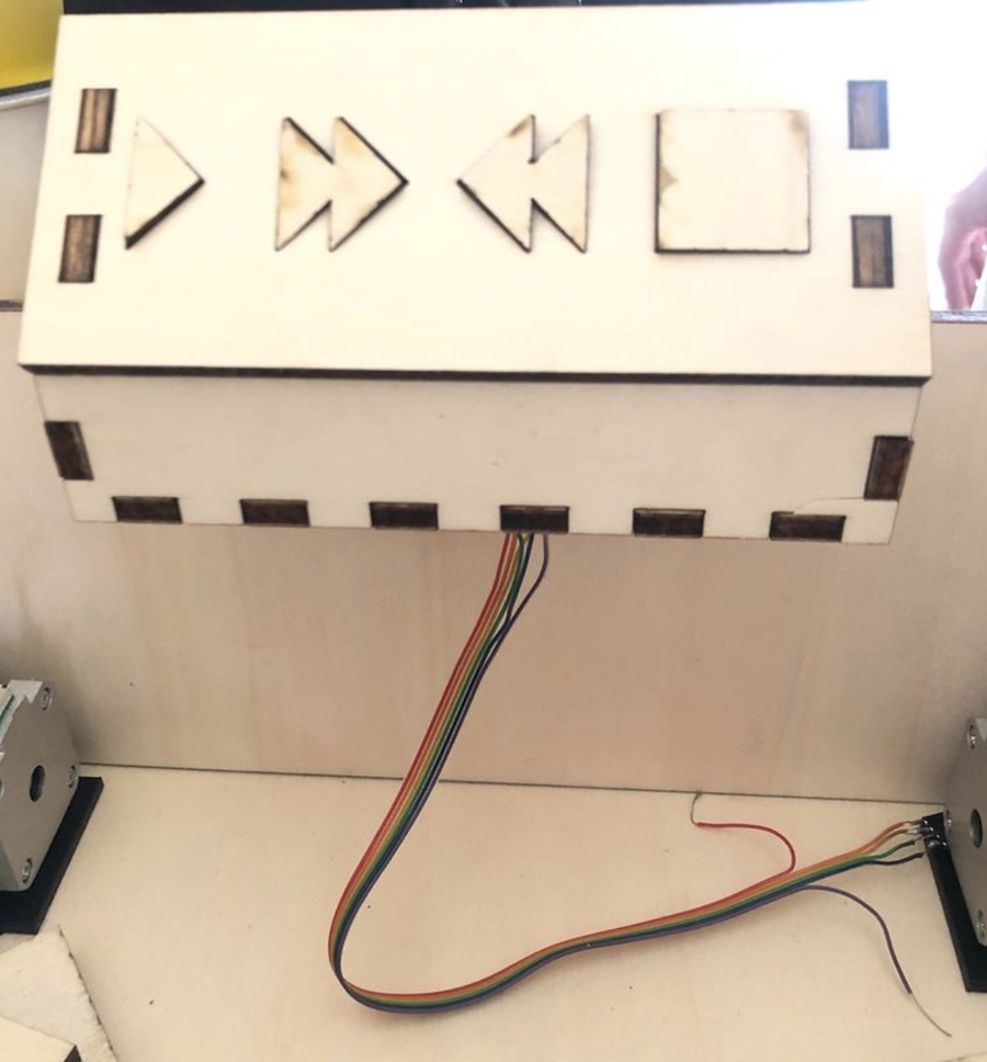
And it fits beautifully on top of the machine. Hiding all the electronics and keeping them safe from ink spatter. Two for one!
Programming the electronics and buttons
To use the machine, I need electronics. With my own board not being finished at this point, I used an arduino and a stepper motor shield from ….
On the shield there are two stepper motor drivers which are very similar to the ones that will be on my board. Having this setup allowed me to test the machine before all electronics were milled and soldered.
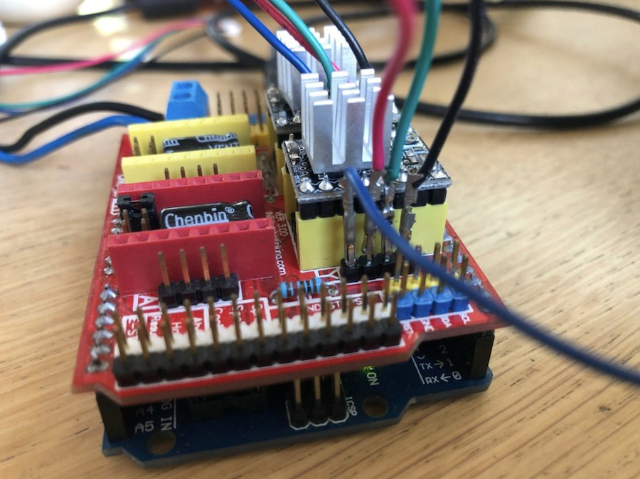
My own board looks like the one below, I added the stepper motor drivers on to the pins. (Always use your schematic to make sure they’re in place properly!)
With the shields in place, it was time to get coding. I took out my friendly robot USB and got started.
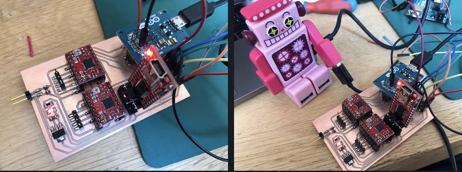
First use the arduino ISP as a programmer to burn the bootloader onto the ATMEGA328. After this is done, you can use the FTDI to programme the chip.
Thanks to these guys for inspiration and tips, I was able to build the code.
https://www.makerguides.com/a4988-stepper-motor-driver-arduino-tutorial/
https://www.instructables.com/Build-your-own-Arduino-Bare-Bone-System/
https://ezcontents.org/programming-atmega328p-barebone
The stepper motors use the following code:
/* Simple Stepper Motor Control Exaple Code by Dejan Nedelkovski, www.HowToMechatronics.com */

#define EN 8
// defines pins numbers
const int Xstep = 24;
const int Xdir = 23;
const int buttonPin = 12;

const int Ystep = 26;
const int Ydir = 25;

int pulses = 1750;
int stepdelay = 500;
int buttonState = 0;
void setup() {
Serial.begin(9600);
// Sets the two pins as Outputs
pinMode(Xstep,OUTPUT);
pinMode(Xdir,OUTPUT);
pinMode(Ystep,OUTPUT);
pinMode(Ydir,OUTPUT);
pinMode(EN, OUTPUT);
pinMode(buttonPin, INPUT);
digitalWrite(EN, LOW);
delay(3000);
}
void rol(){
digitalWrite(Xdir,HIGH);
digitalWrite(Ydir,HIGH); // Enables the motor to move in a particular direction
// Makes 200 pulses for making one full cycle rotation
for(int x = 0; x < pulses; x++) {
digitalWrite(Ystep,HIGH);
digitalWrite(Xstep,HIGH);
delayMicroseconds(stepdelay);
digitalWrite(Ystep,LOW);
digitalWrite(Xstep,LOW);
delayMicroseconds(stepdelay);
}
delay(1000); // One second delay
digitalWrite(Xdir,LOW);
digitalWrite(Ydir,LOW); //Changes the rotations direction
// Makes 400 pulses for making two full cycle rotation
for(int x = 0; x < pulses; x++) {
digitalWrite(Ystep,HIGH);
digitalWrite(Xstep,HIGH);
delayMicroseconds(stepdelay);
digitalWrite(Ystep,LOW);
digitalWrite(Xstep,LOW);
delayMicroseconds(stepdelay);
}
delay(1000);
}
void loop() {
buttonState = digitalRead(buttonPin);
Serial.println(buttonState);
if (buttonState == LOW) {
rol();
} else {
}
}
With the motors and buttons attached to the PCD and the code on the chip, it’s time for testing.

The rolling systems moves forwards nicely, but when turning back it seems that one motor started earlier than the other. To fix this, I had to change the Ampere on the driver shields. You do this by using a plastic (yes, non-conductive) screwdriver and turn the screw on the shield. Once you found the correct setting, leave it 🙂
With this in place, time for another test!

Yes!! Time to make a bunch of stamps 🙂
Stamps
I’ve been making linoleum stamps my whole life. I use plain linoleum, rubber erasers, wood, … Anything I can find.
The process is super easy: you etch or carve, you put on ink, place a paper or piece of fabric on top (make sure you use suitable ink ;-)) and you apply pressure.
Because we have so many technology in the lab that allows us to make stamps using the different processes, I did a couple of tests.
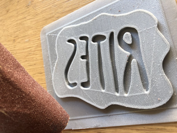
The most obvious one: a 3D-printed stamp
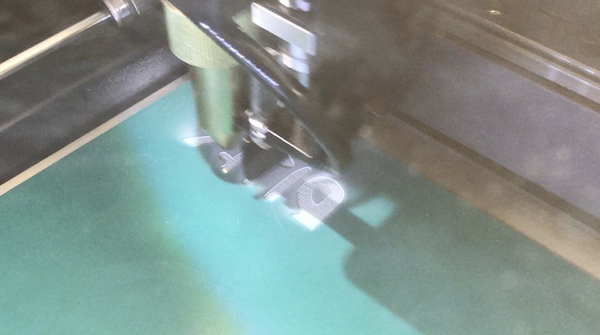
I used the logo I designed for the band Rites during the 3D-design cycle. I only made it a bit less high. It was printed using the normal ultimaker settings and then sanded with a rougher piece of sanding paper.
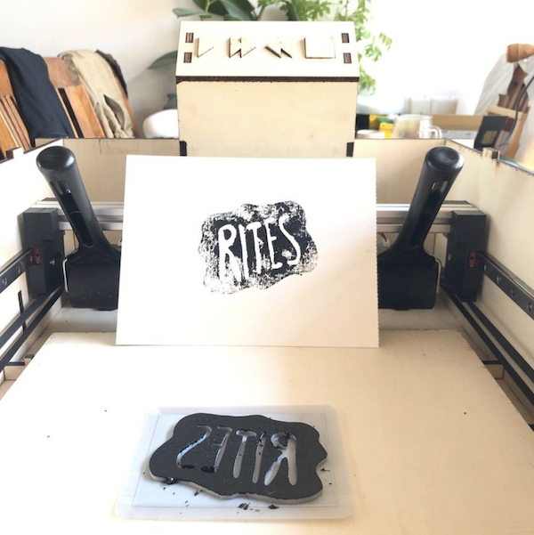
It was placed on the bed of the machine and ink was applied.
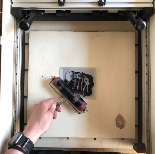
Once the machine put pressure on it, it came out really nice. So, onto other materials.
I used a couple of different materials:
- poplar
- mdf
- eco rubber
- stamping rubber
- linoleum
I engraved the poplar, ecorubber, stamping rubber and linoleum. The mdf was milled and the contour laser cutted.
They all looked great, but way too clean!
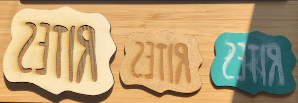
I played with ink and the stamps for a little hour. The wooden once needed a bit of sanding, as did the 3D-printed stamp. The others are made for printing so no extra sanding was necessary.
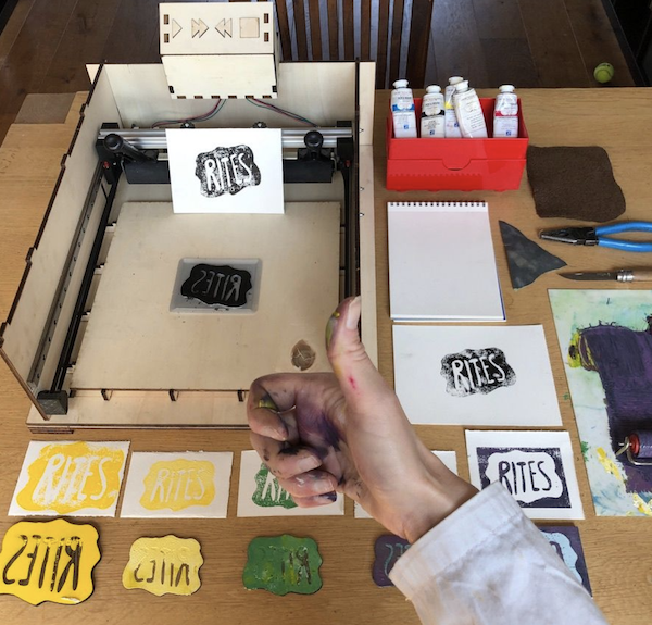
Making pictures in between the printing was difficult with everything being dirty, so I ended up having a hero shot of the final results.
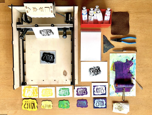
Needless to say I had a lot of fun, very dirty hands and additional colours on my lab coat. All prove of an afternoon well spent!
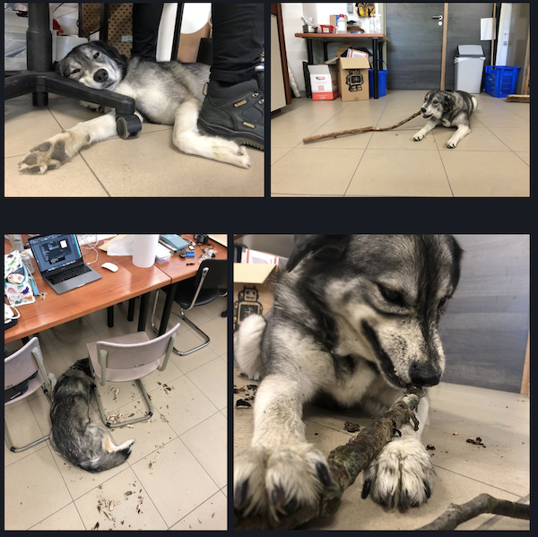
Mysa’s time in the lab
She had all the fun and found new weird ways to sleep…
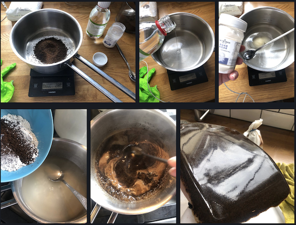
Extra: bioplastic
I wanted to do research on using bio plastic as a base for stamps. As a coffee lover, the obvious base for this was, well, used ground coffee. I have tons of this so I was curious to see if and how it could be used in stamps.
I used the following recipe, based on both [materiom] as a workshops we previously followed.
- 160 g water
- 8 g agar agar
- 22 g glycerine (with Bush running in the back of my head)
- 34 g finely ground coffee
- 6 g white thin clay
Steps:
- Boil the water
- Add the glycerine and agar agar
- Once it boils, put in the coffee and clay
- Leave it boil for a good five minutes, stirring your heart out (otherwise it sticks)
- Pour it in a container (I used a glass one to have a smooth surface)
- Leave it for about five minutes
- Take it out of the container (otherwise it stays moist and moulds tend to form)
- Leave it to dry for a couple of days
It will curl, so turn it over now and then. After a few days you should have something like this.
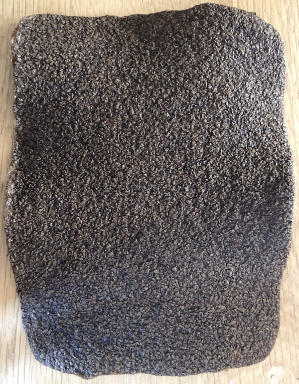
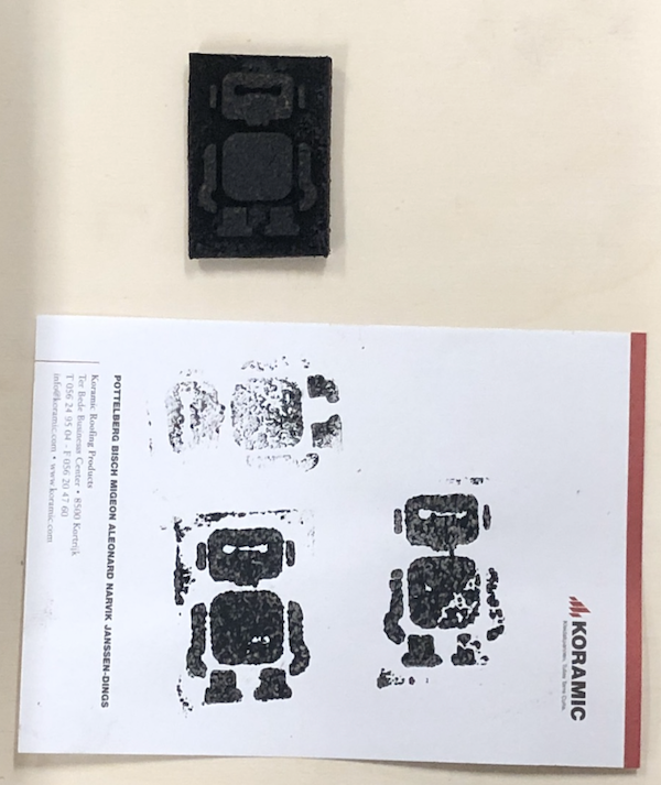
As I focused on finishing the machine, I haven’t been able to test the rubber yet to see whether you can engrave it. Kurt however tried out his piece and it came out really nice!
Bom: list of materials
| Part/component | Description | Quantity | Price |
|---|---|---|---|
| Rubber roll system | |||
| Stepper motors | motor | 2 | 9,91 euro |
| Timer belts | 1 m | 2 | 3,37 euro |
| Nuts | M3 | 12 | 0,4 euro |
| M6 | 4 | 0,2 euro | |
| Threaded rod | M6 - 2 x 7 cm | 2 | 1 euro |
| Screws | M3 | 24 | 0,5 euro |
| PLA for the prints | 1 roll of filament | 1 | 20 euro |
| Rubber roll | 30 cm | 1 | 25 euro |
| Maker beam | 35 cm | 1 | recycled |
| Button controller | |||
| Poplar plywood | shared with the casing | 1 | 22 euro |
| Wire | 2 m | 1 | 1 euro |
| Buttons | Single pole push button | 4 | 2,12 euro |
| Resistors | 220 ohm | 4 | 0,06 |
| Machine casing | |||
| Poplar plywood | see above | ||
| Electronics | |||
| Copper board | 55 x 85 mm | 1 | 1,5 euro |
| Polulu break-out boards | A4988 | 2 | 5,95 euro |
| Capacitator | 10µF | 2 | 0,2 euro |
| Header | HEADER FEMALE, 2.54mm CC, 1 ROW, SMT | 4 | 0,4 euro |
| PINHD-1x04-SMD-HEADER | 2 | 0,2 euro | |
| PINHD-1x02-SMD-HEADER | 1 | 0,1 euro | |
| PINHD-1x03-SMD-HEADER | 6 | 0,1 euro | |
| FTDI-SMD-HEADER | 1 | 0,5 euro | |
| AVRISPSMD | 1 | 0,17 eruo | |
| LED | red | 1 | 0,2 euro |
| Resistor | 220 ohm | 1 | 0,06 euro |
| 10K | 1 | 0,06 euro | |
| Switch | 6mm switch | 1 | 0,6 euro |
| Chip | ATmega328p-AU | 1 | 2,07 euro |
| Power regulator | 5V regulator | 1 | 0,3 euro |
| Crystal | ECS-CR2-20.00-B-TR | 1 | 0,2 euro |
| Power supply | 12v laptop power supply | 1 | recycled |
Files
Laser cut parts
Machine casing and button controller
3D-print parts
2x Motor holder 2x - pause at 59 % Knobs rubber roll 2x Clamps rubber roll 2x Rubber roll holder 2x Belt idler
Electronics
KiCad pro KiCad Scheme KiCad pcb KiCad Libraries PCB png
Code
License
I choose to work with a Attribution-NonCommercial-ShareAlike 4.0 International (CC BY-NC-SA 4.0)

In long, this means the following:
This is a human-readable summary of (and not a substitute for) the license. Disclaimer.
You are free to:
- Share — copy and redistribute the material in any medium or format
- Adapt — remix, transform, and build upon the material
- The licensor cannot revoke these freedoms as long as you follow the license terms.
Under the following terms:
- Attribution — You must give appropriate credit, provide a link to the license, and indicate if changes were made. You may do so in any reasonable manner, but not in any way that suggests the licensor endorses you or your use.
- NonCommercial — You may not use the material for commercial purposes.
- ShareAlike — If you remix, transform, or build upon the material, you must distribute your contributions under the same license as the original.
- No additional restrictions — You may not apply legal terms or technological measures that legally restrict others from doing anything the license permits.
Notices:
- You do not have to comply with the license for elements of the material in the public domain or where your use is permitted by an applicable exception or limitation.
- No warranties are given. The license may not give you all of the permissions necessary for your intended use. For example, other rights such as publicity, privacy, or moral rights may limit how you use the material.
A big thank you
To Kurt, for the input, help and support. Always. To Nous, for support, input and the food behind the scenes. To Mysa, for being you and keeping my feet warm in the lab.