10. Input devices
In this week we had to measure something. We needed to add a sensor to a microcontroller board that we have designed and read it.
Individual assignment
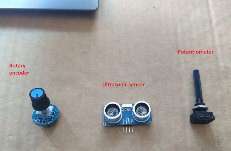
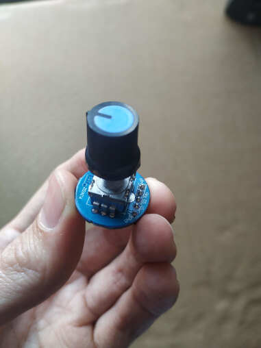
I used three different sensors, ultrasonic sensor (HC-SR04), rotary encoder and potentiometer. You can see it in a picture bellow.
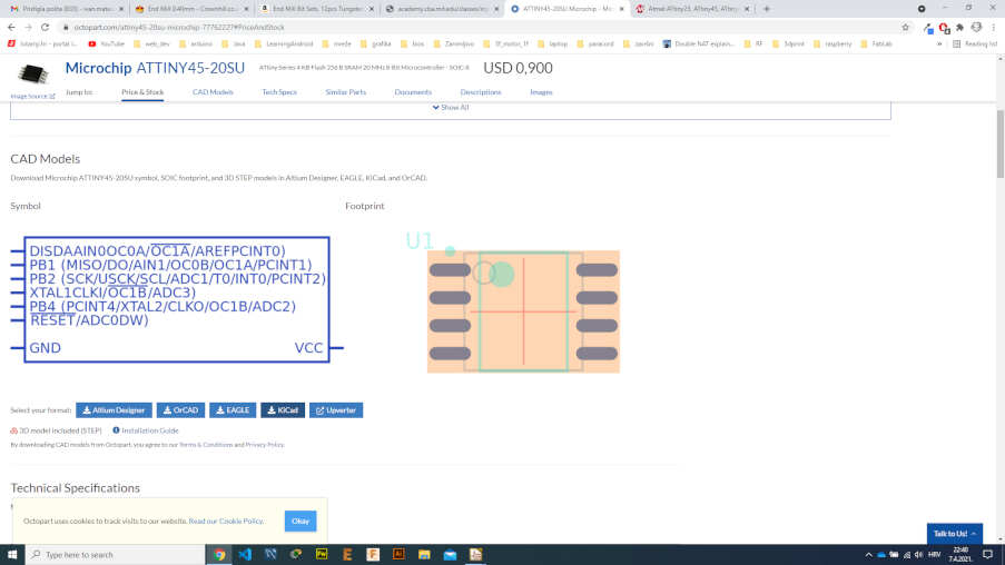
First I needed to design and make my own board. I started design PCB in KiCAD. When I was designing PCB in electronic design week, I noticed that footprint of ATtiny45 was little smaller then the one I have. I was having trouble soldering ATtiny45 to the bord. So, I go to octopart.com and downloaded the CAD model for KiCAD and add it to the library.
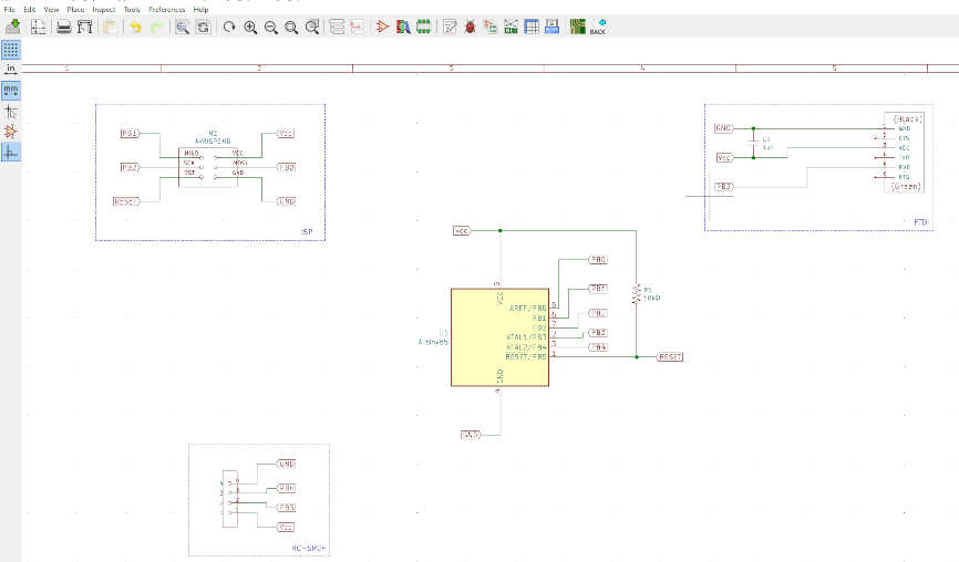
I go to new project and first started drawing schematic. I put ISP header for programming and FTDI pins for communication. I also place 4 pins on board for connecting ultrasonic sensor (HC-SR04). I was thinking that these pins later I can reuse to connect other sensors.
Once I was done with schematic I generated netlist and saved it. In the next step I go pcbnew to create a PCB. I imported netlist and got the following results.
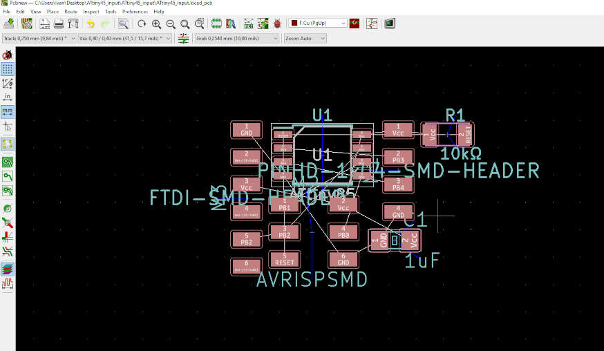
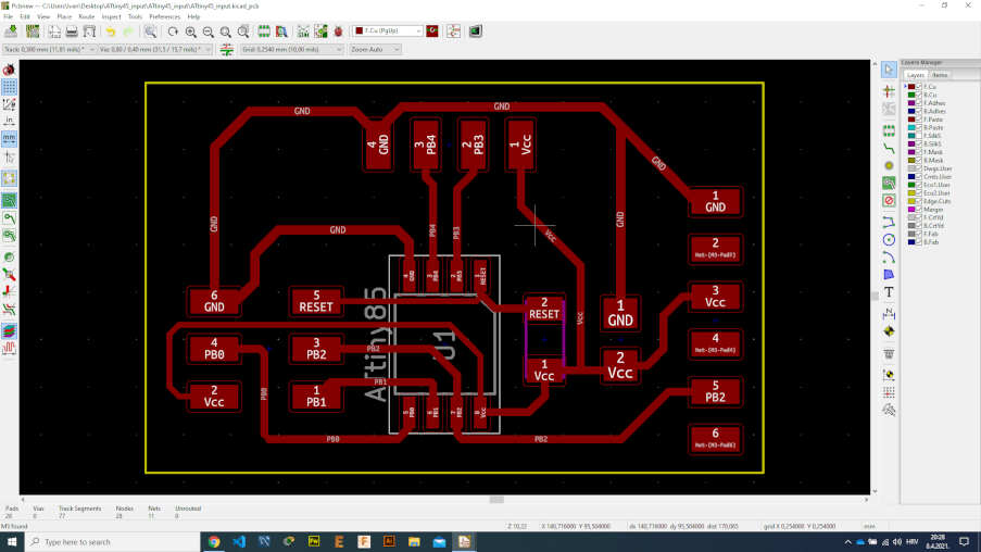
After some time with arranging parts, drawing lines to connect all the parts I got finished PCB. In the end I drew a border, where I need to cut. You can see the finished board in a picture bellow.
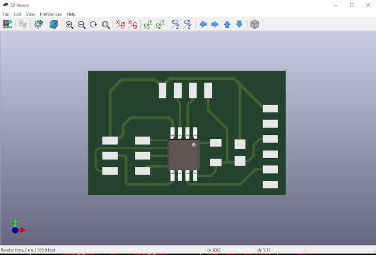
By clicking ALT+3 I got the 3D view of the PCB.
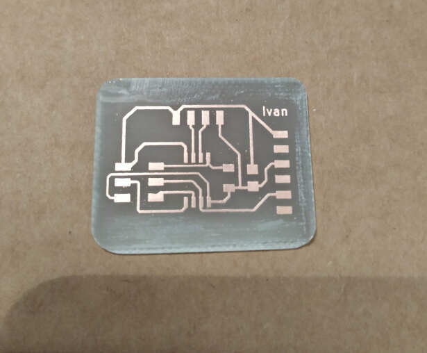
I also performed deign rules check and there was no errors. I exported PCB as svg. To make a PCB this time I used an etching method. After the PCB is exposed to the UV light it goes into the developer and then in a etching solution. Whole process can be seen in Electronic production and design week. You can see finished PCB.
Next thing was to solder the components to the PCB. I used this components:
- 10kΩ resistor
- 1uF capacitor
- ATTiny85 Microcontroller
- ISP and FTDI header
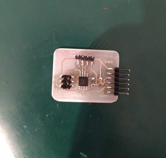
After soldering the components the results can be seen here.
HC-SR04 Ultrasonic distance sensor consists of two ultrasonic transducers. The one acts as a transmitter which converts electrical signal into 40 KHz ultrasonic sound pulses. The receiver listens for the transmitted pulses. If it receives them it produces an output pulse whose width can be used to determine the distance the pulse travelled. The sensor offers excellent non-contact range detection between 2 cm to 400 cm with an accuracy of 3mm. On the following picture you can see pinouts of ultrasonic sensor (HC-SR04).
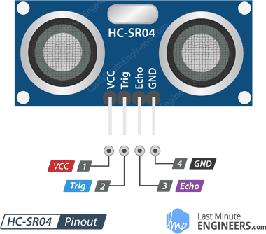
- Vcc – 5V power supply pin
- Trigger - used to trigger the ultrasonic sound pulses
- Echo - produces a pulse when the reflected signal is received
- Gnd – ground pin
It all starts, when a pulse of at least 10 µS (10 microseconds) in duration is applied to the Trigger pin. In response to that the sensor transmits a sonic burst of eight pulses at 40 KHz. The eight ultrasonic pulses travel through the air away from the transmitter. Meanwhile the Echo pin goes HIGH to start forming the beginning of the echo-back signal. If those pulses are reflected back the Echo pin goes low as soon as the signal is received. This produces a pulse whose width varies between 150 µS to 25 mS, depending upon the time it took for the signal to be received.
For calculating distance we use simple formula where distance = speed x time. Because signal is reflected in the end we need to divide by 2.
For programming and testing ultrasonic sensor I found some arduino and processing sketch here. I found out that ATtiny85 does not have UART so I can’t use hardware serial for communication. I needed to modify arduino sketch to use software serial in order to work in processing.
#include <Mouse.h>
#include <SoftwareSerial.h>

SoftwareSerial TinySerial(1, 2); // RX, TX

const int trigpin = 3; //connection between
const int echopin = 4;  //ATtiny85 and sonar
long duration;
int distance;
void setup()
{
  pinMode(trigpin,OUTPUT);
  pinMode(echopin,INPUT);
  TinySerial.begin(9600);

}
void loop()
{
  digitalWrite(trigpin,HIGH);
  delayMicroseconds(10);      //send 10us pulse
  digitalWrite(trigpin,LOW);
  duration=pulseIn(echopin,HIGH);
  distance = duration*0.034/2;  //calculate distance
  TinySerial.println(distance); //display distance over serial
}
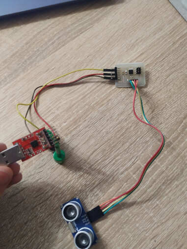
Processing is used for visualization to display distance in cm. I programmed my microcontroller using ISP header. After programming I connect my board and PC with FTDI cable.
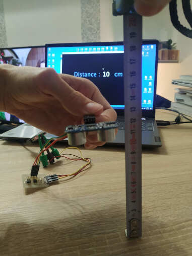
I run the processing sketch to display distance. The results can be seen in a video bellow. I also tried to put obstacle at an angle. This causes ultrasonic signal to deflect so it can’t measure properly.
I compared measured distance in processing with a tape measure. You can see that the results are the same.
Group assignment
For the group assignment we had to probe an input device’s analog levels and digital signals. I used rotary encoder for digital signal and potentiometer for analog signal. A rotary encoder is a type of position sensor which is used for determining the angular position of a rotating shaft. It generates an electrical signal, either analog or digital, according to the rotational movement. This rotary encoder is also known as quadrature encoder or relative rotary encoder and its output is a series of square wave pulses. Iit’s the simplest position sensor to measure rotation. On the following picture you can see encoder pinouts.
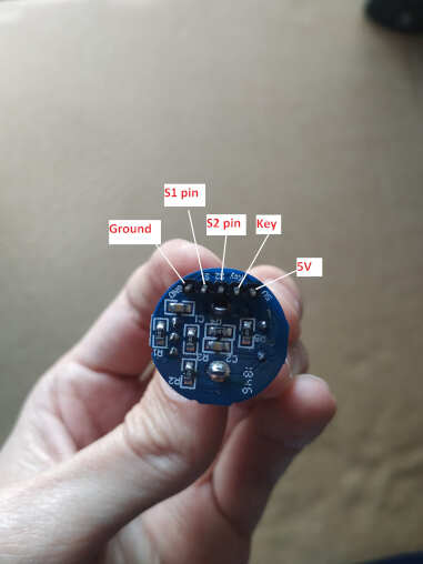
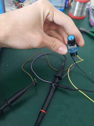
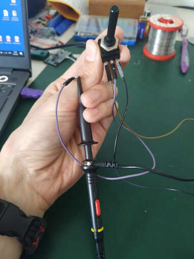
I hooked up oscilloscope probes to pins S1 (channel 1) and S2 (channel 2) of the encoder to determine the rotation. Is it clockwise or counterclockwise. Encoder was connected to 5V supply. I did not use switch pin. This is used as an ordinary momentary switch.
Let’s take a closer look at the encoder and see its working principle. Here’s how the square wave pulses are generated: The encoder has a disk with evenly spaced contact zones that are connected to the common pin C and two other separate contact pins A and B (in our case is S1 and S2), as illustrated below.
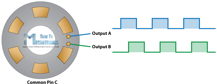
When the disk will start rotating step by step, the pins S1 and S2 will start making contact with the common pin and the two square wave output signals will be generated accordingly.
Any of the two outputs can be used for determining the rotated position if we just count the pulses of the signal. However, if we want to determine the rotation direction as well, we need to consider both signals at the same time. The following signal is obtained from oscilloscope when I was turning rotary encoder in clockwise direction.
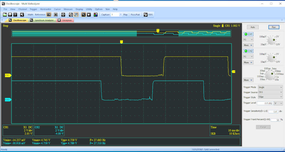
I set trigger mode on oscilloscope to single and trigger style to detect edge. We can notice that CH2 or S2 pin trigger faster than CH1 (S1 pin). Next signal is obtained from oscilloscope when I was turning rotary encoder in counterclockwise direction.
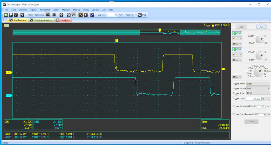
We can notice that CH1 or S1 pin trigger faster than CH2 (S2 pin). On this way we can determine the rotation of encoder, either clockwise or counterclockwise.
To observe the analog signal I used ordinary potentiometer. Potentiometer has three terminals. The outer left and right in my case are fixed value and that was 25KΩ. The middle pin is wiper (adjustable value). I connect outer left and right terminal to 5 volts and ground. The middle pin I connected to oscilloscope probe.
At its base, an analog signal is a continuous signal in which one time-varying quantity (such as voltage, pressure, etc.) represents another time-based variable. In the following video you can see how the analog signal changes when I turn potentiometer. The values vary from 0V to 5V.
Digital signals, by contrast, is a set of discrete values (on/off, 0 or 1, true or false).