Fourth week
Fourthclass
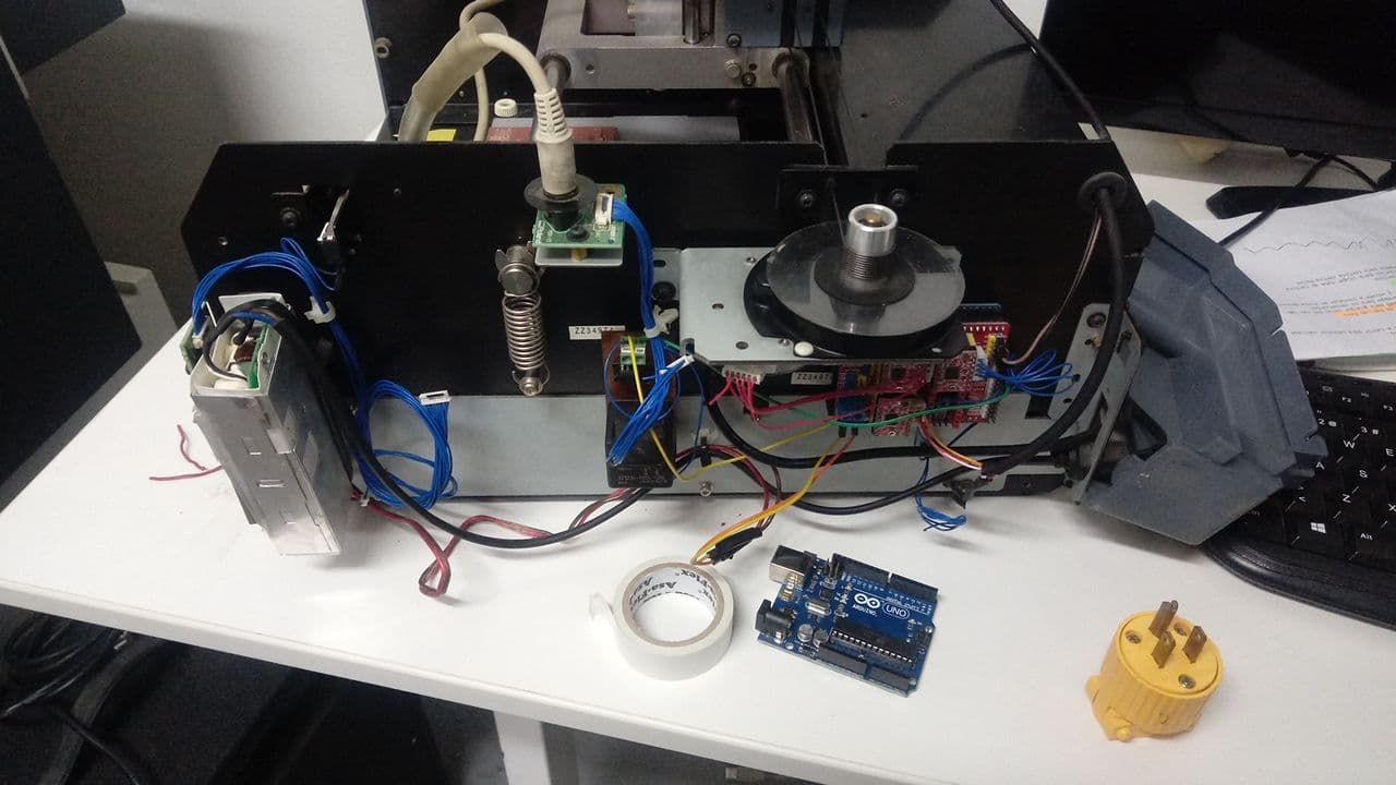
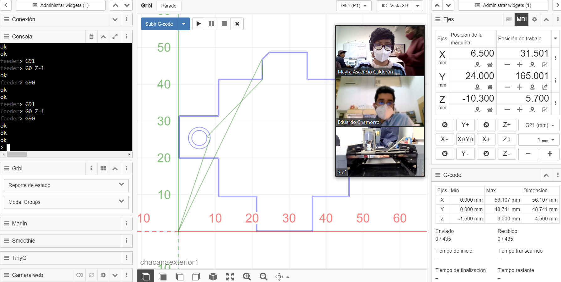
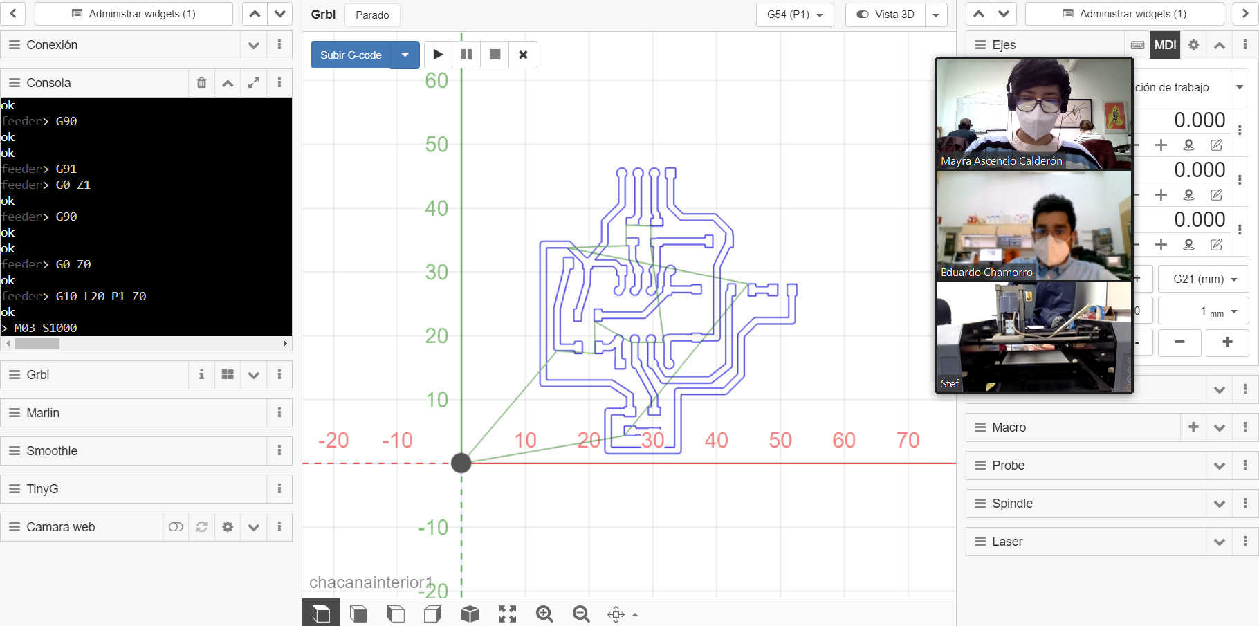
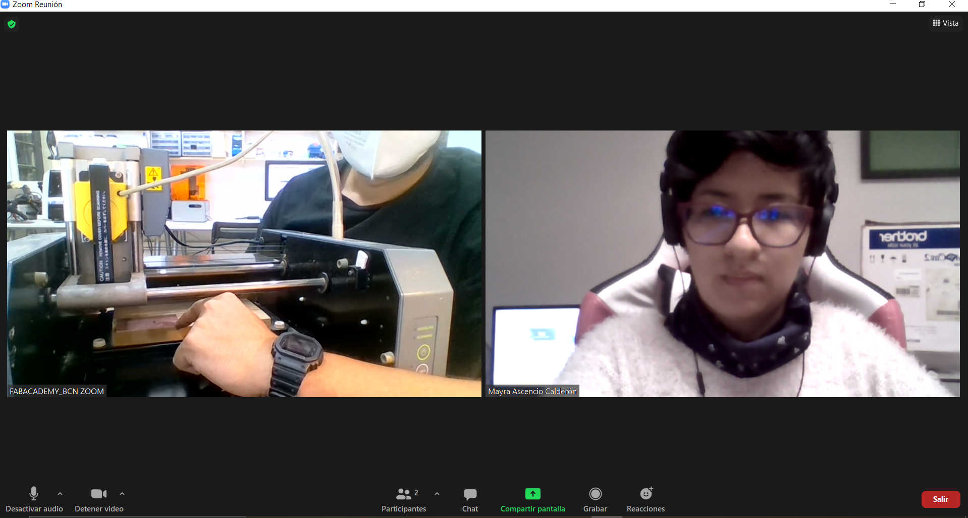
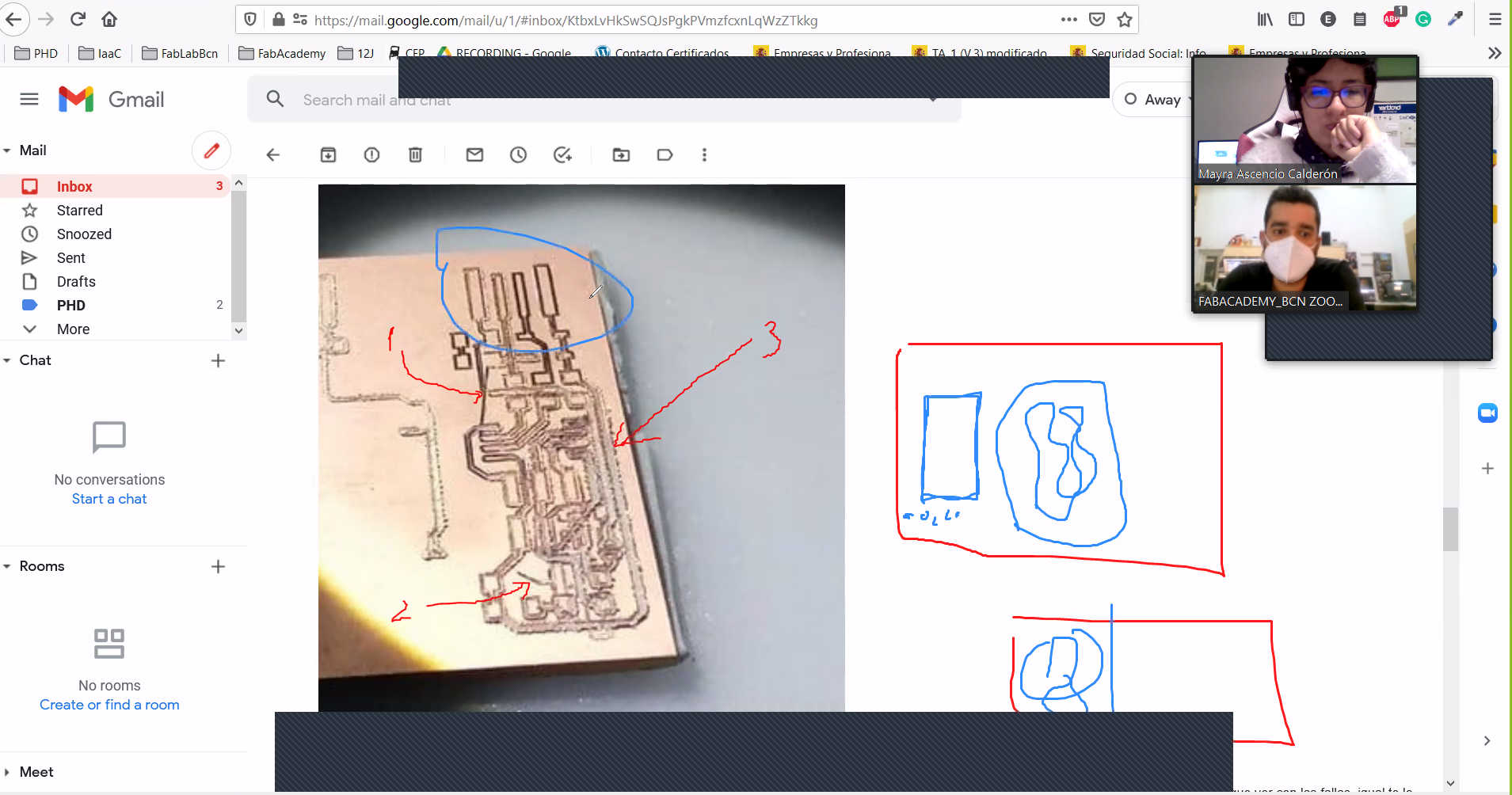
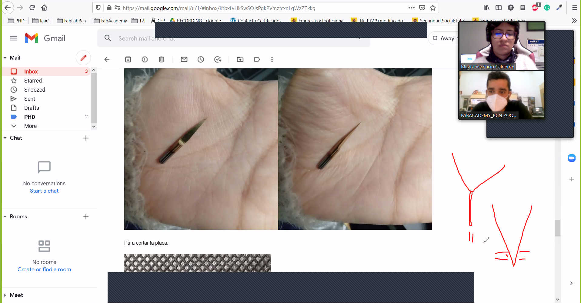
This February 17 was the Electronics production class and I found it interesting that I didn't understand even half of the session. I have no experience in anything electronic and this is the first time I see board topics so I'm sure this week will be a real adventure. On Wednesday I decided to volunteer for the second time to expose how difficult it was for our team to solve the task with the broken machine, I think when you have challenges like this we learn more as we test ourselves with problem solving.
Anyway I know it will be fun and I will keep on working hard to get the best results, I thank once again to the Barcelona team for all the support from afar and of course to my heart team Fab Lab Peru. 💓
Second time as a volunteer
My experience
General concepts
- Voltage: Electrical voltage or potential difference (also called voltage) is a physical quantity that quantifies the difference in electrical potential between two points. It can also be defined as the work per unit charge exerted by the electric field on a charged particle to move it between two given positions. It can be measured with a voltmeter. Its unit in the International System of Units (SI) is the volt.
- Conductive materials: Conductive materials are those that offer little resistance to the passage of electricity. Electrons can circulate freely through the material because they are weakly bound to the atoms and can therefore conduct electricity. For example: aluminum, bronze, nickel, gold.
- LED: A light-emitting diode or LED (also known as a light-emitting diode) is a light source consisting of a semiconductor material with two terminals.
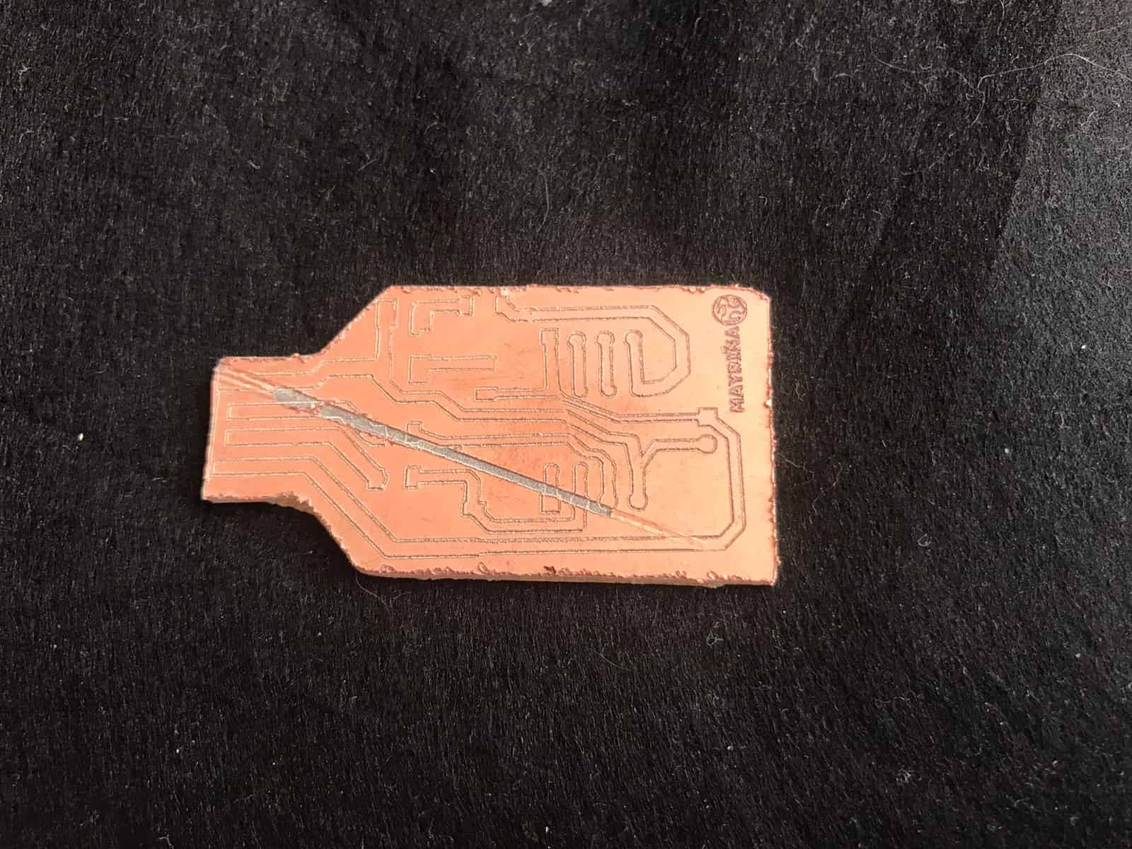
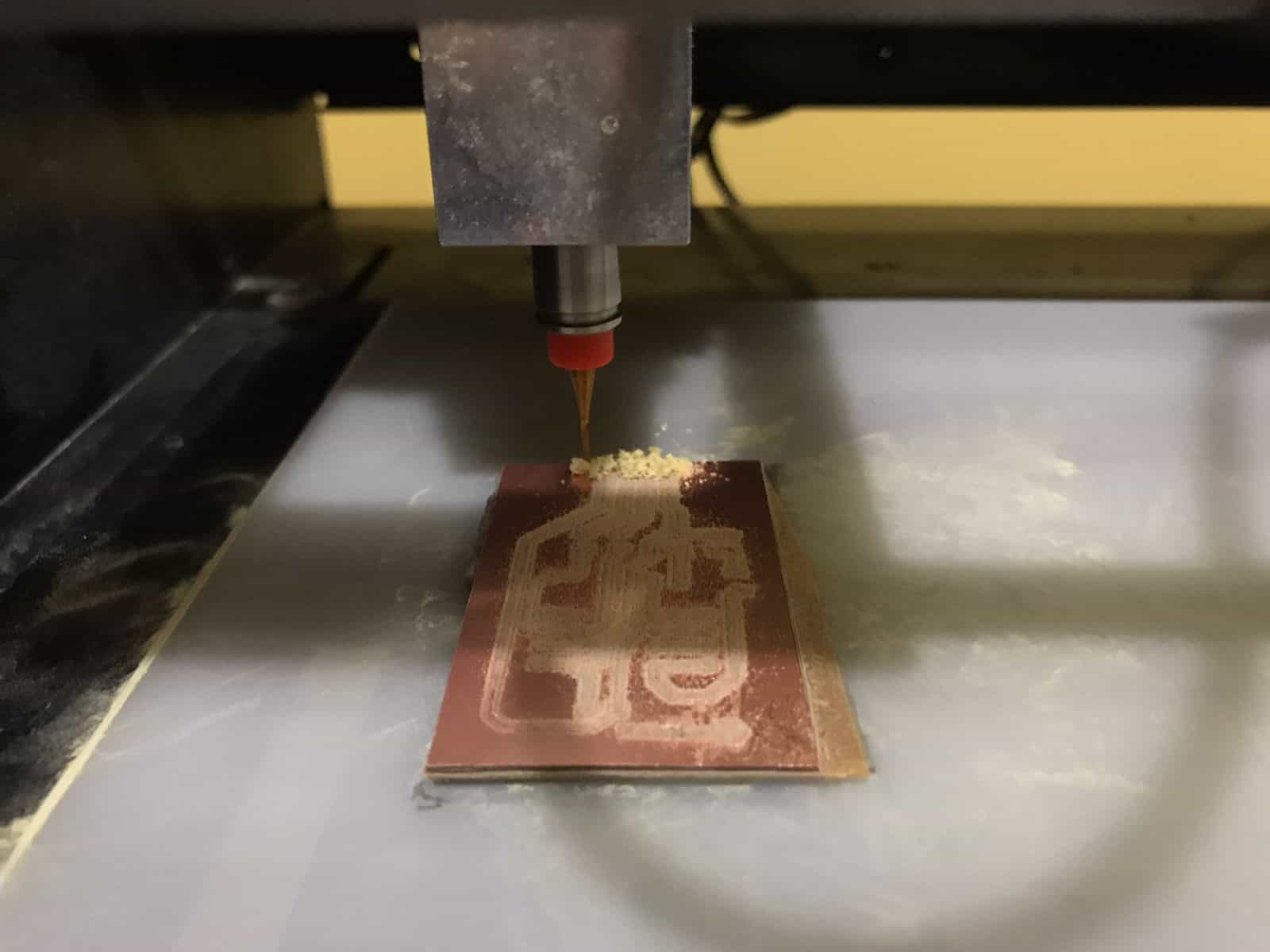
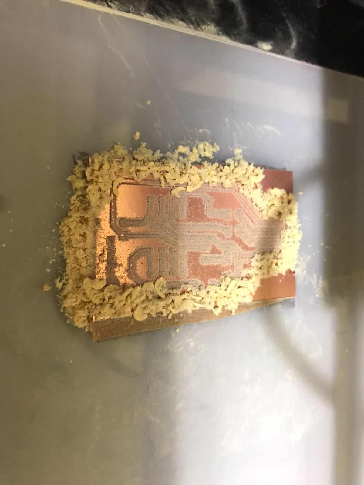
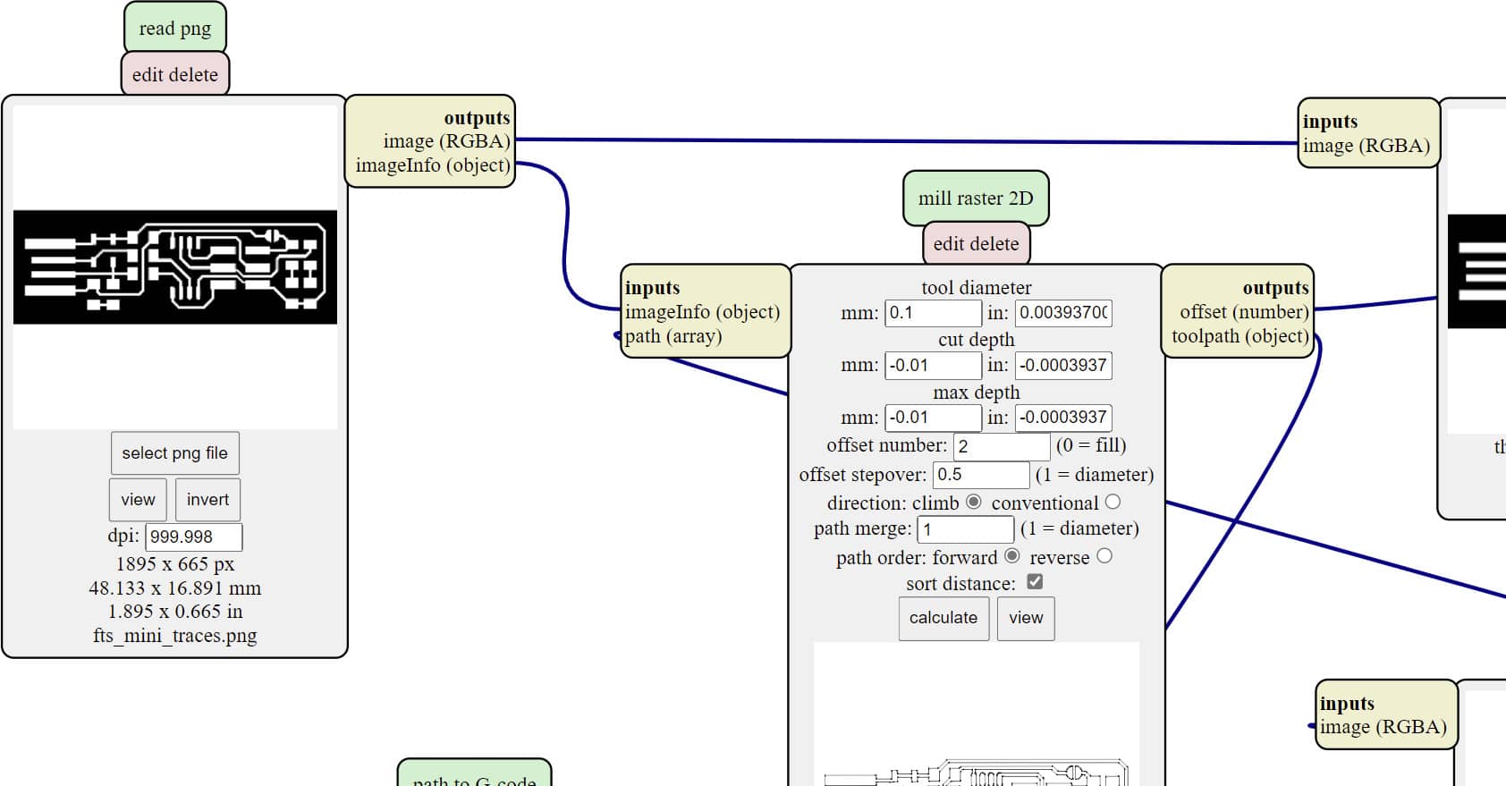
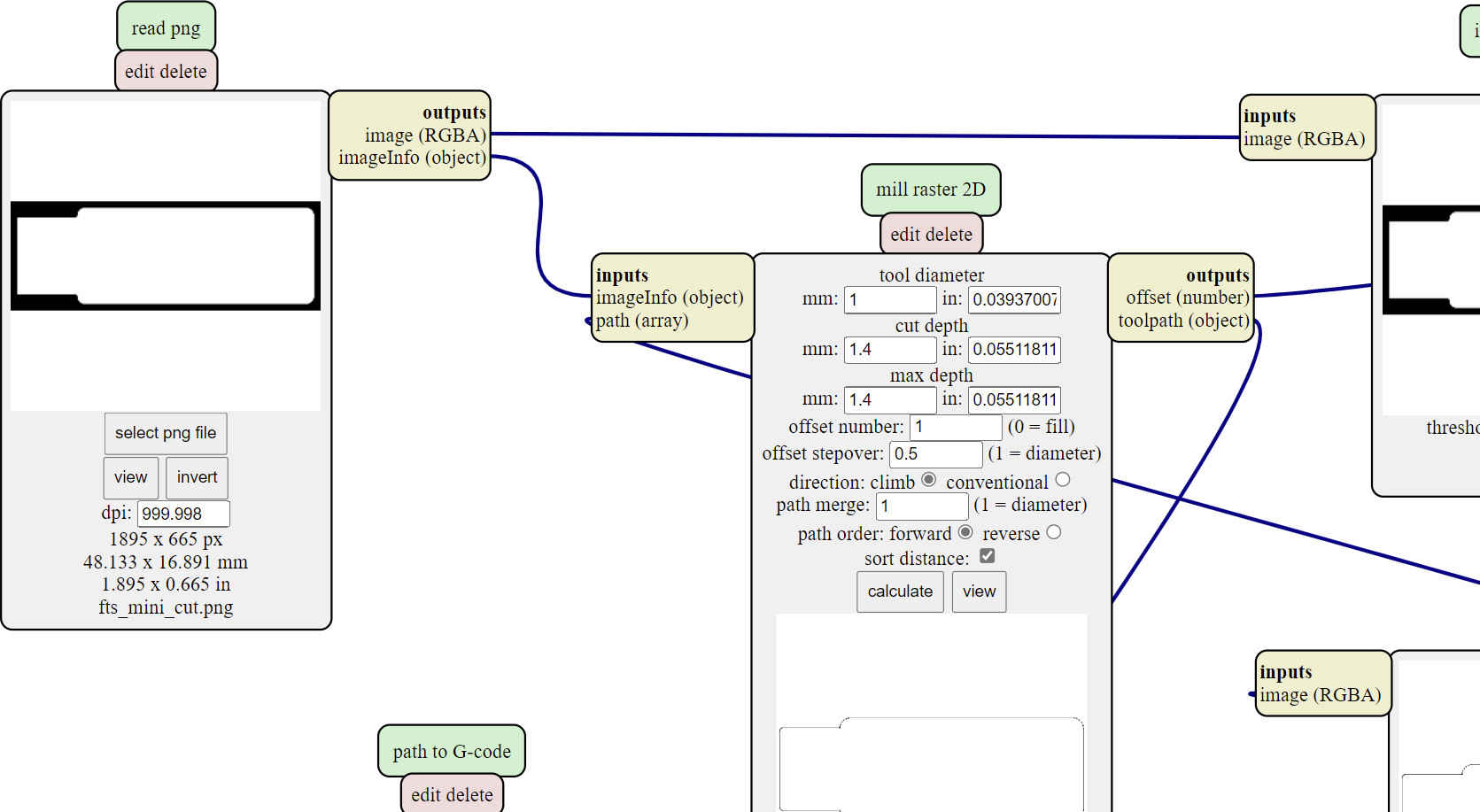
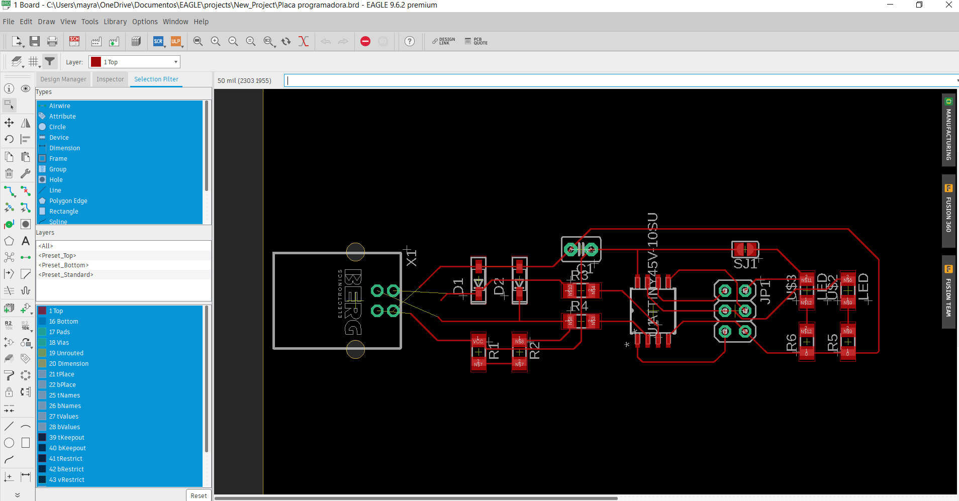
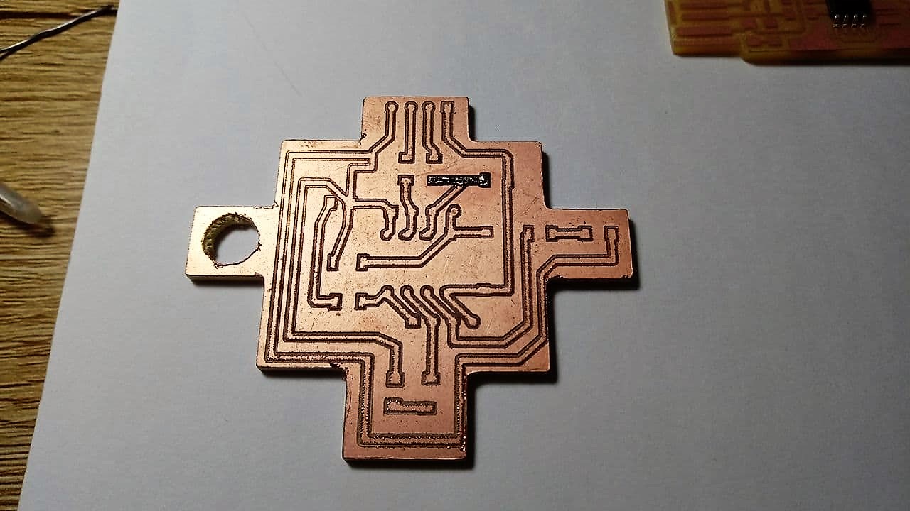
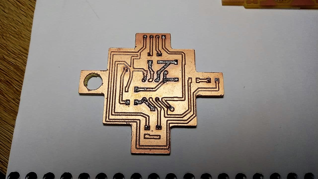
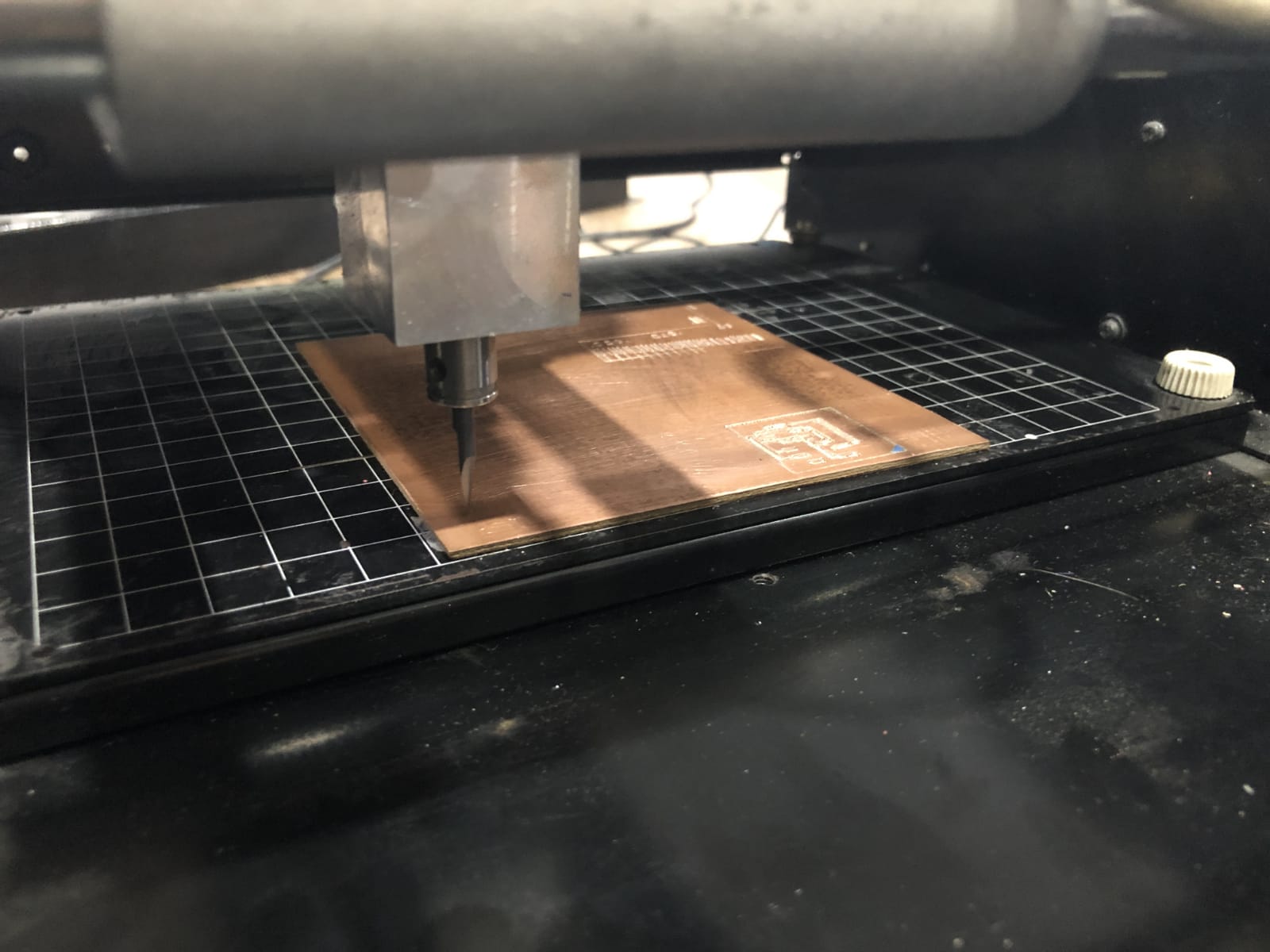
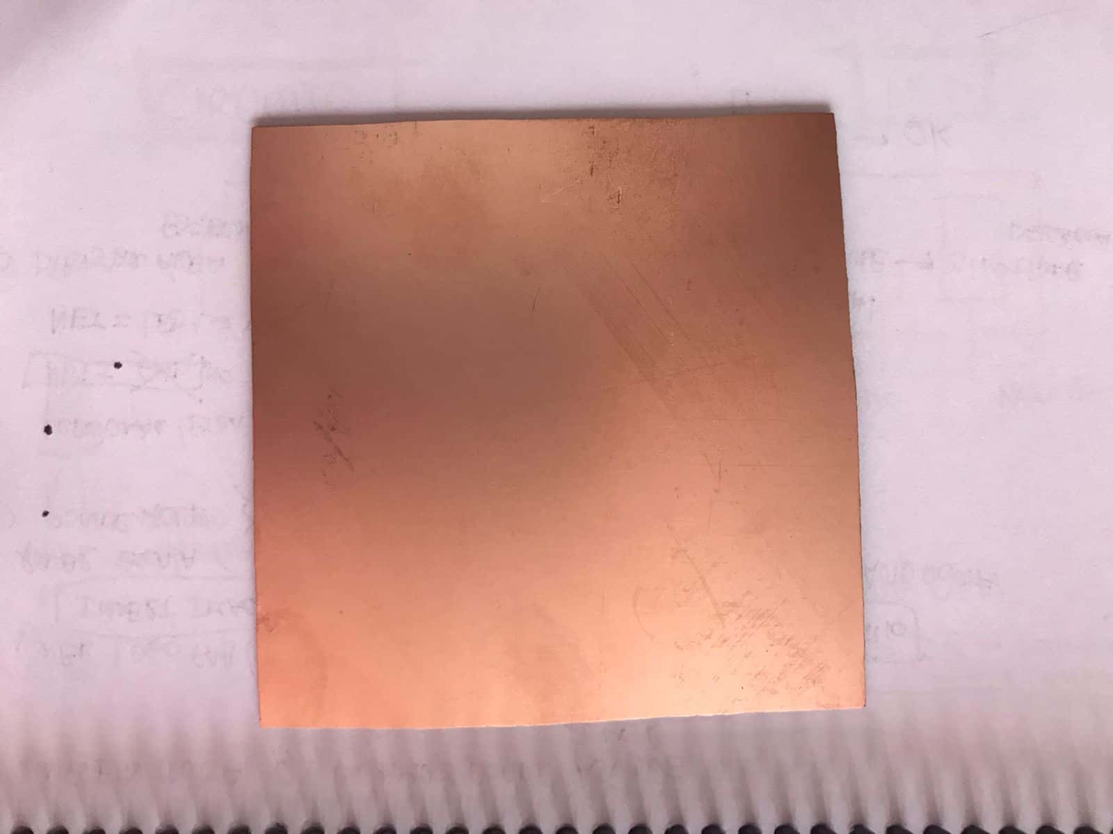
- PCB: A printed circuit board is a circuit whose components and conductors are contained within a mechanical structure. Conductive features include copper traces, terminals, heat sinks or flat conductors. The mechanical structure is made of insulating laminated material sandwiched between layers of conductive material. The overall structure is plated and covered with a non-conductive solder mask and a printing screen for electronic component legend location.
- Electronics components: Electronic components are the devices that make up the circuits that make appliances that we use in our day-to-day life work, such as cell phones, televisions or hair dryers. They come encapsulated in ceramic, metal or plastic. They usually have two or more metal terminals or pins.
- Resistors: These are the components in charge of "opposing" the flow of electric current. They are in charge of slowing down or attenuating it to prevent it from flowing without any control. Their resistance capacity is measured in ohms (Ω) and their power, i.e. the amount of electricity they can control without burning out, in watts (W).
- Capacitors: These are found near resistors and can store an electrical charge temporarily. There are many varieties, but the most common are electrolytic and ceramic disc capacitors. Their capacity is measured in microfarads (μF).
- Diodes: These elements allow electric current to flow in one direction only, as long as the positive voltage is applied to the diode terminal known as the anode and the negative to the terminal called the cathode. If it is done the other way around, the electric current will not pass.
- Transistors: These are one of the most important devices in electronics and have three terminals. Voltage is applied to the base, which controls the current passing through the other two terminals, the collector and the emitter.
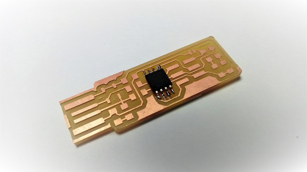
- Integrated circuits: This is one of the most special electronic elements as they contain, in themselves, an entire electrical circuit. The most modern electronic devices, such as computers or cell phones, are built from this type of element. Although this represents an advance, it is also true that it makes the reuse of components and their repair more difficult, and makes us more dependent on the technical services of large companies. A fact that is closely related to planned obsolescence.
- Integrated circuits: An anode and a cathode are the two types of terminals in an electronic device. The cathode is the terminal where current leaves an electronic device. The anode is the terminal where current flows into an electronic device. Electrical current is the amount of charge passing a fixed point in a unit of time.
- AVR: AVR is a family of microcontrollers developed since 1996 by Atmel, acquired by Microchip Technology in 2016. These are modified Harvard architecture 8-bit RISC single-chip microcontrollers.
- RISC: RISC-V (pronounced "Risk-Five") is a free hardware instruction set architecture (ISA) based on a RISC (reduced instruction set) design.
(Source: Wikipedia.com)
First steps
To understand this assignment
- The first step I had to take, since I am not familiar with these electronics issues, was to do a lot of research. It is important to know the why of the processes in order to understand how to develop what we want to have as a result. Thanks to many tutorials and interaction with the equipment I was able to experience many things before moving on to theory. My recommendation is that for those who are as proactive as me and don't like the theoretical part, look for tutorials to make DIY models and test them. 👍
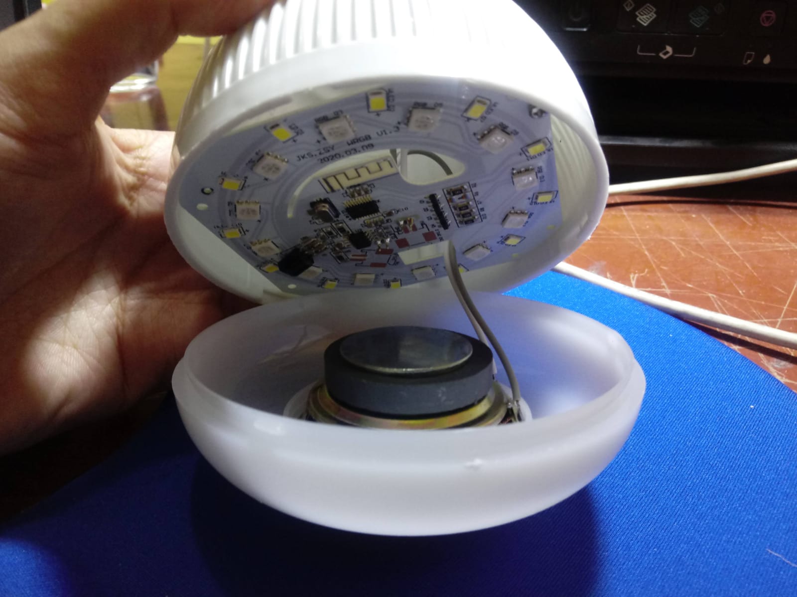
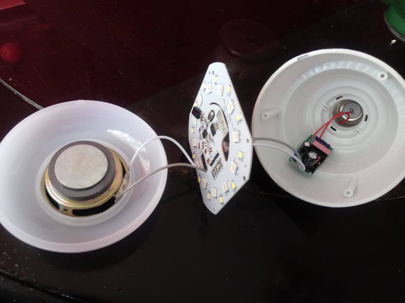
- Well, the first way to investigate was to open some things at home that had some logic of using boards and LEDs. I had never done it before but thanks to this I could see and touch live how is the internal structure of objects like a smart light bulb, a simple lamp and a mouse.
Smart focus
Smart focus
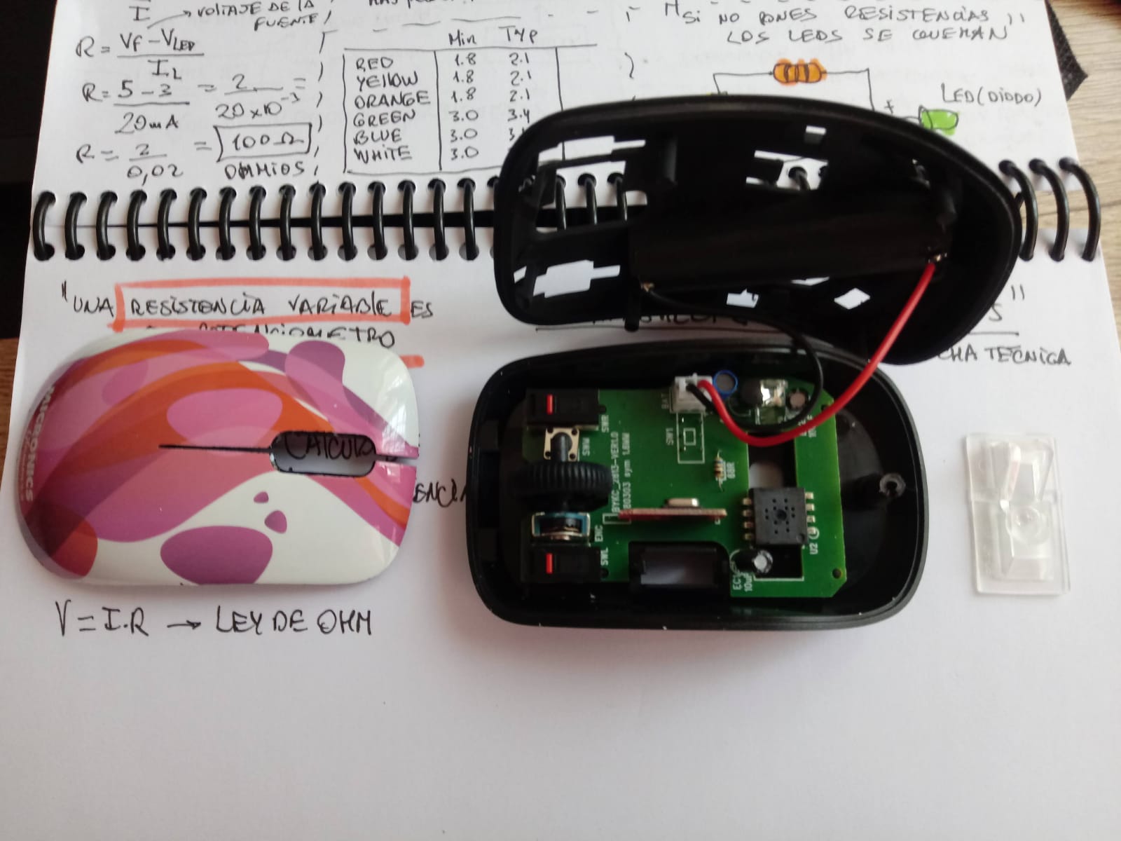
Disassembled mouse
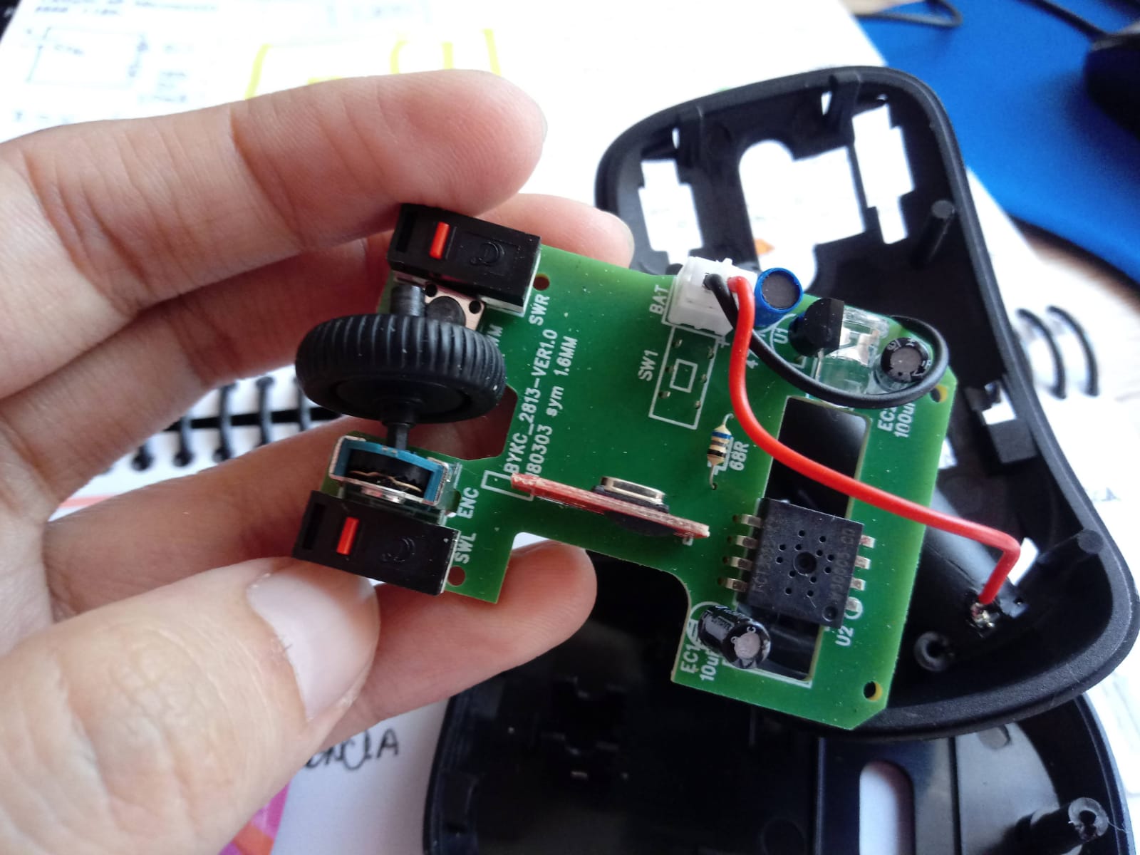
Disassembled mouse
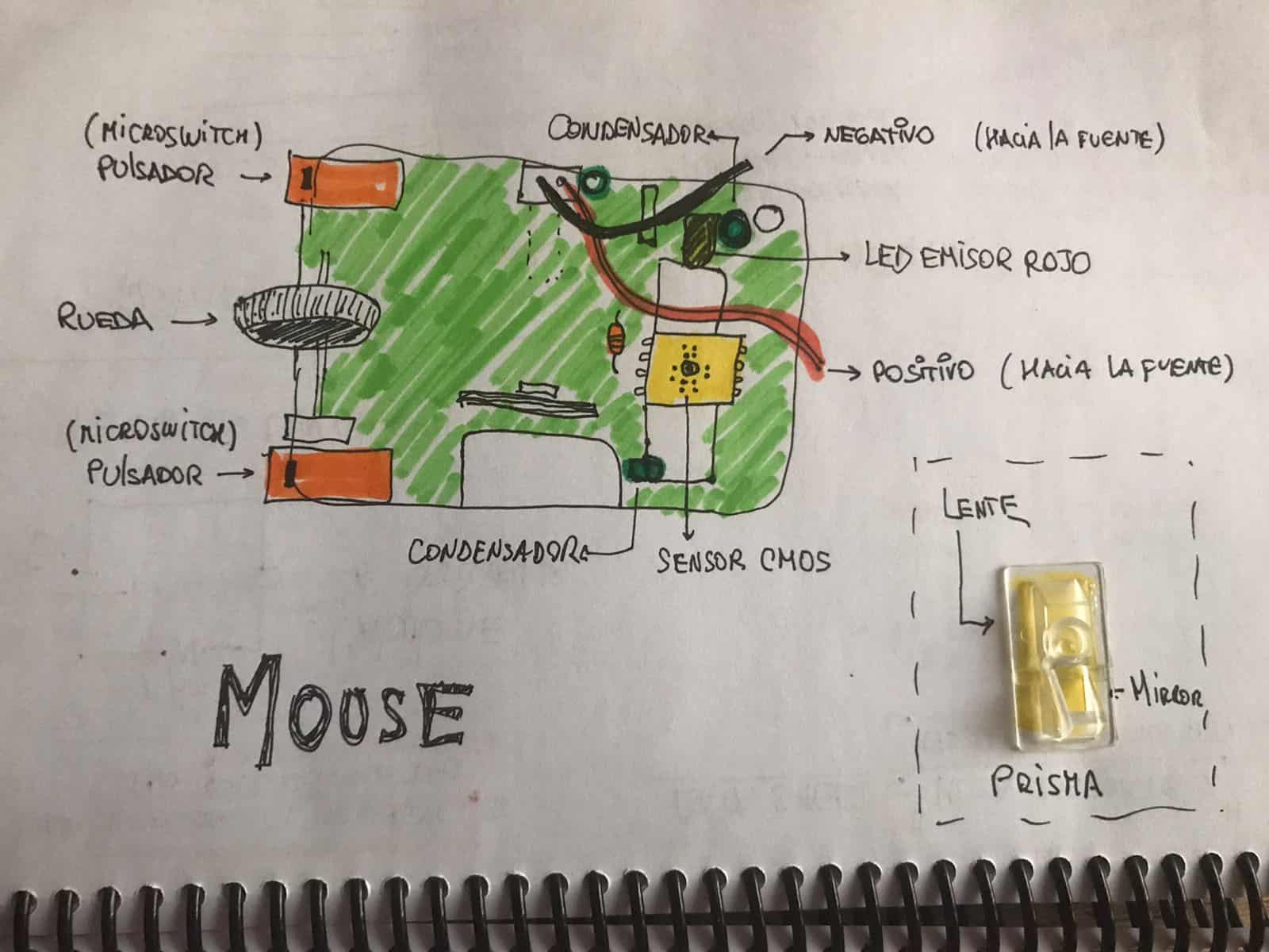
My first graphic
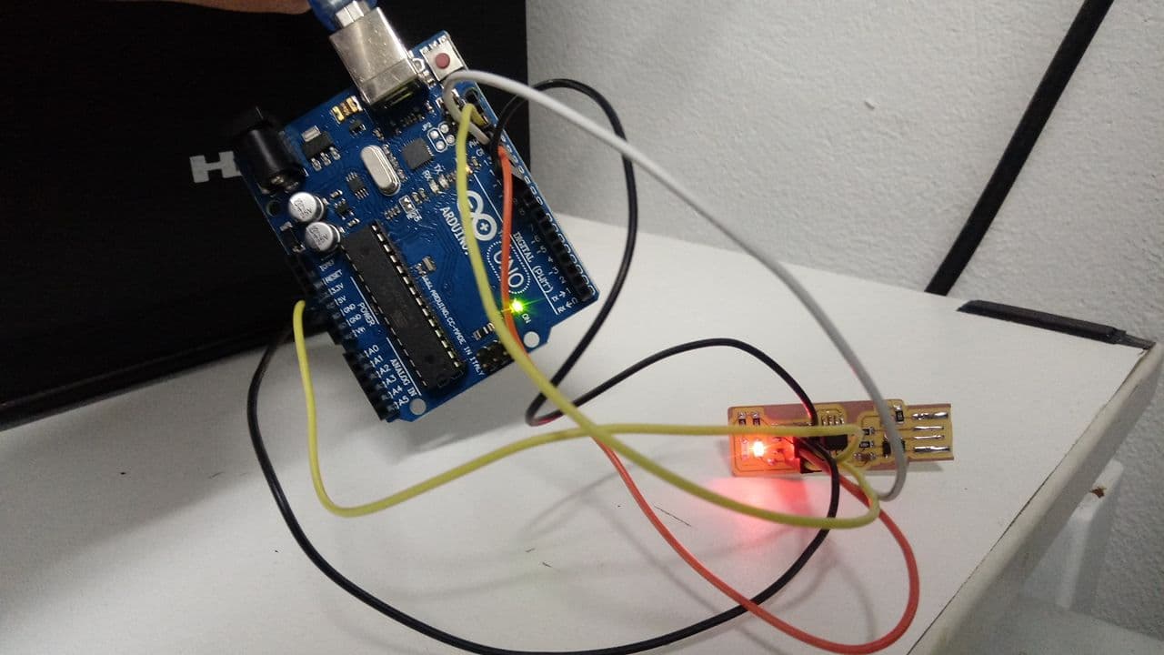
- This exercise helped me to know what I had to understand first, when I saw some leds on the boards it occurred to me to look for how to turn on a led since I had never done it, this gave me very good results since I could understand some concepts like resistance, led, voltage, etc. To be able to build a board and understand its components I investigated in many ways the sequences and connections, this method can help a lot to people like me who are not engineers or knowledgeable about the electronics part.
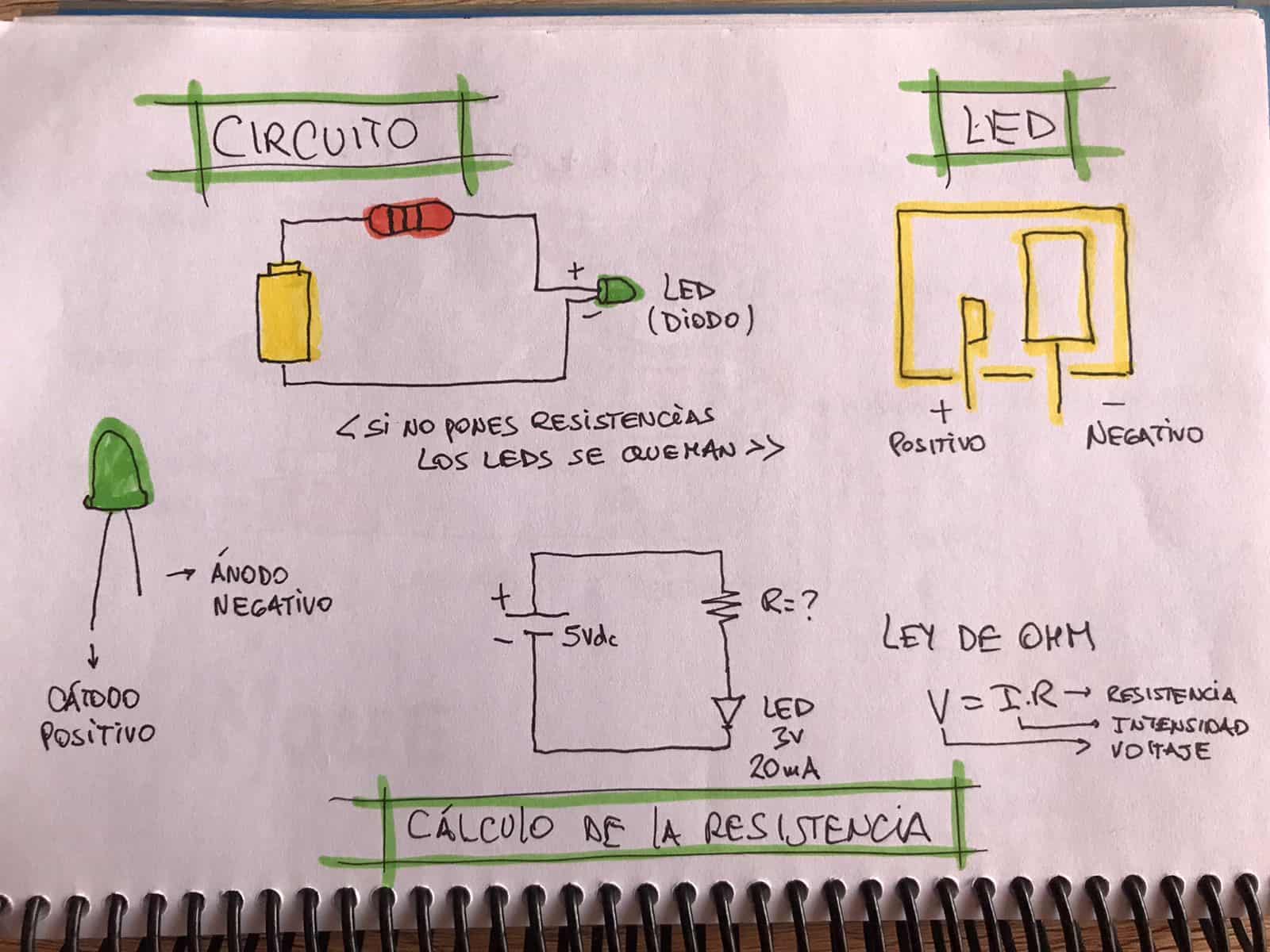
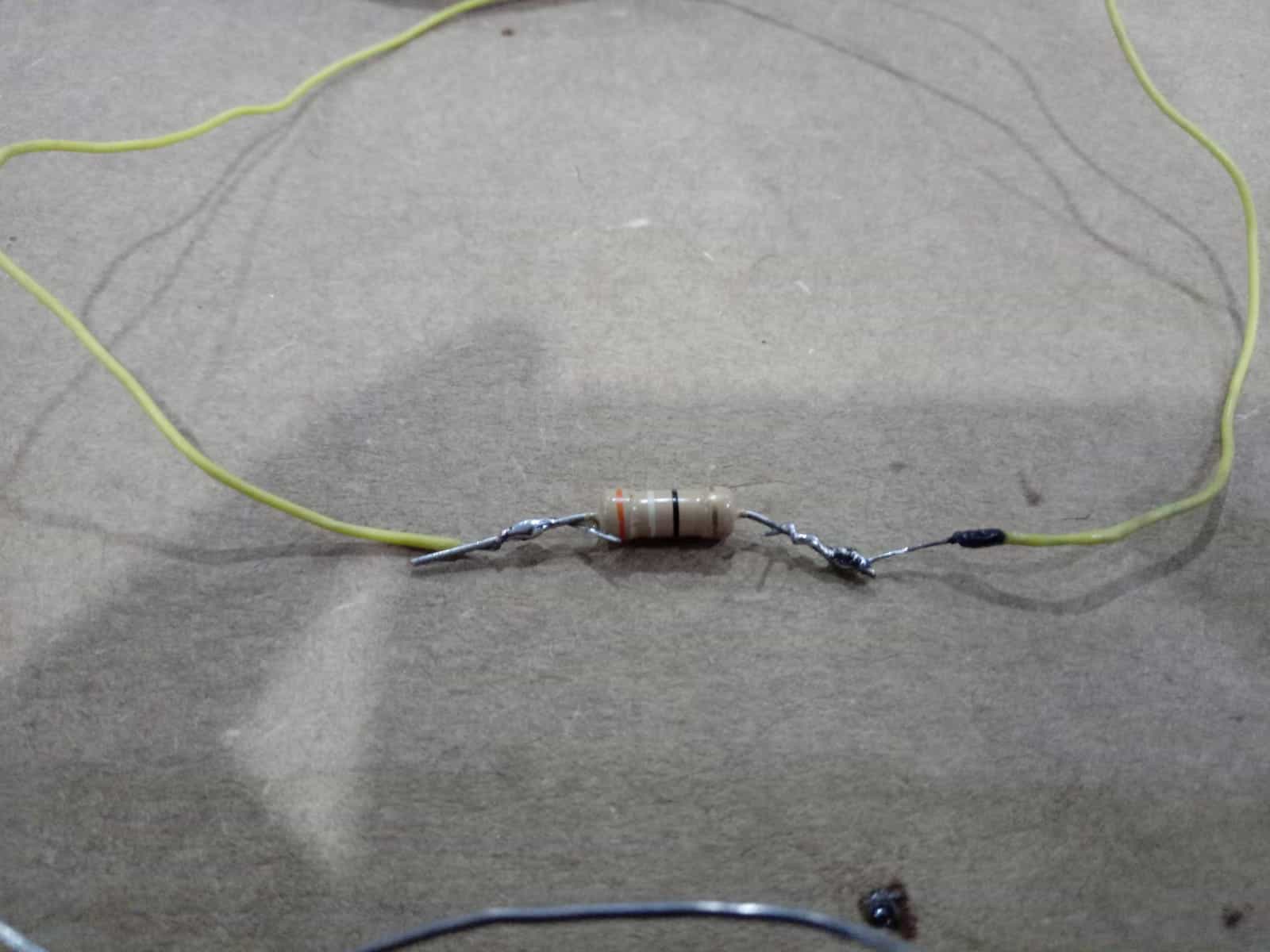
After understanding the conceptual part of the circuits I ventured to perform two experiments, the first was to light an LED with the basics such as an old battery and a resistor. Thanks to the Fab Lab in Lima I was able to get some components and I took them home. The first test was great, for the first time in my life I turned on an LED.
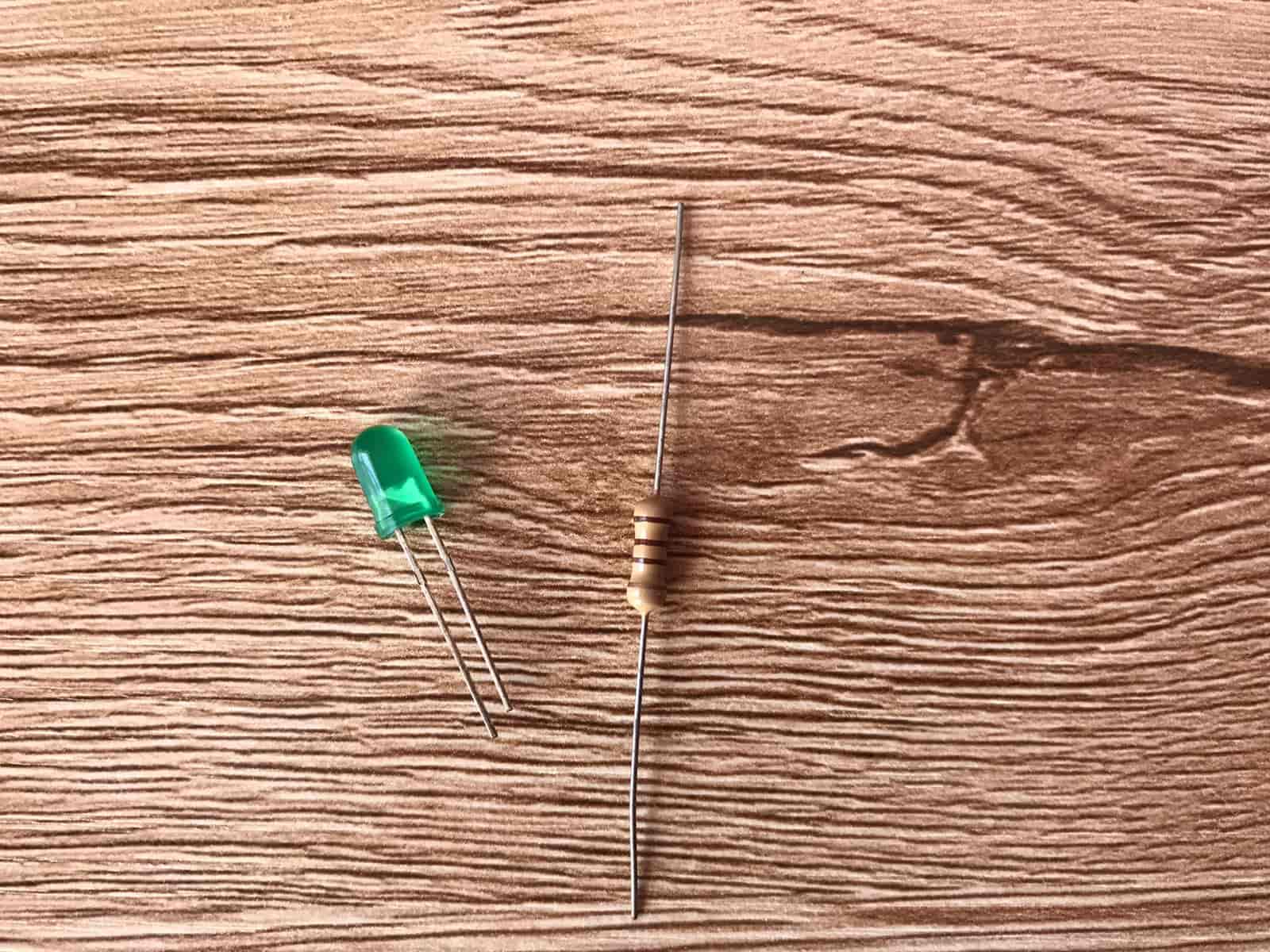
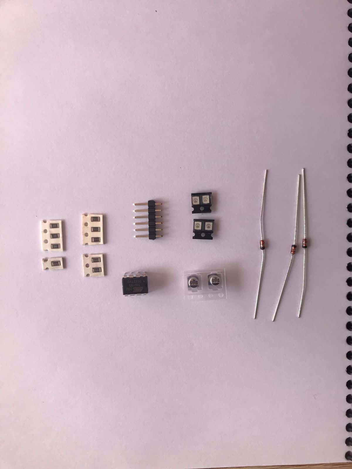
Components LED and Resistor
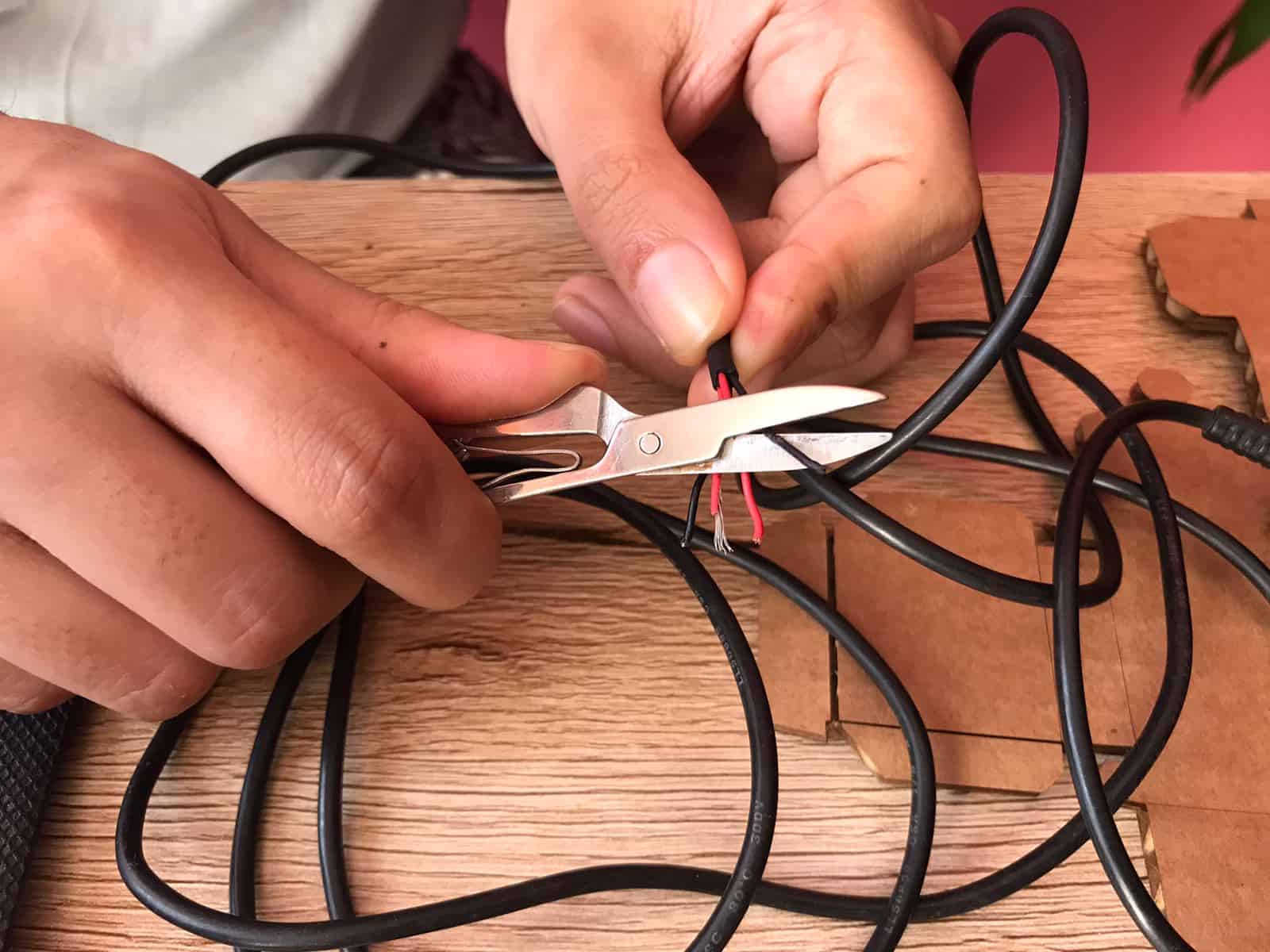
Stripping wires
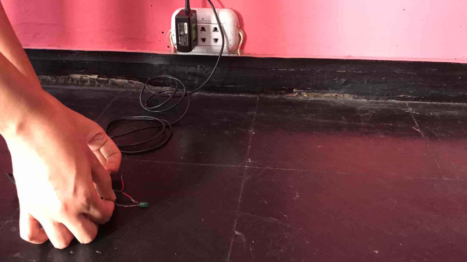
Connecting positive and negative
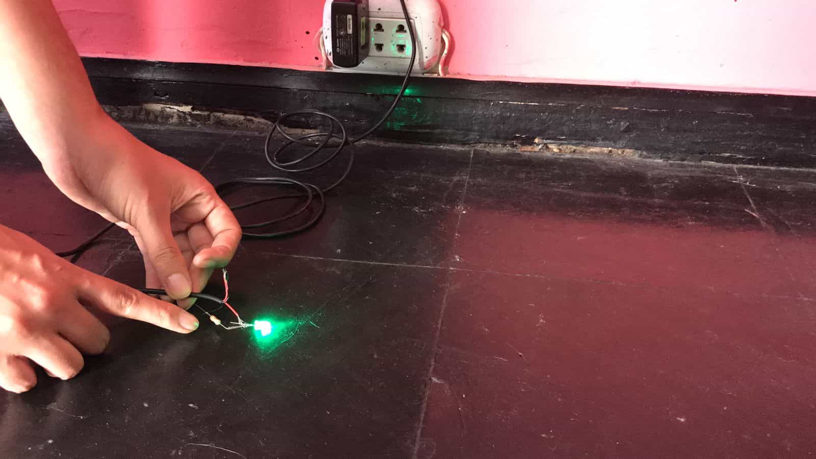
¡Turning on the led!
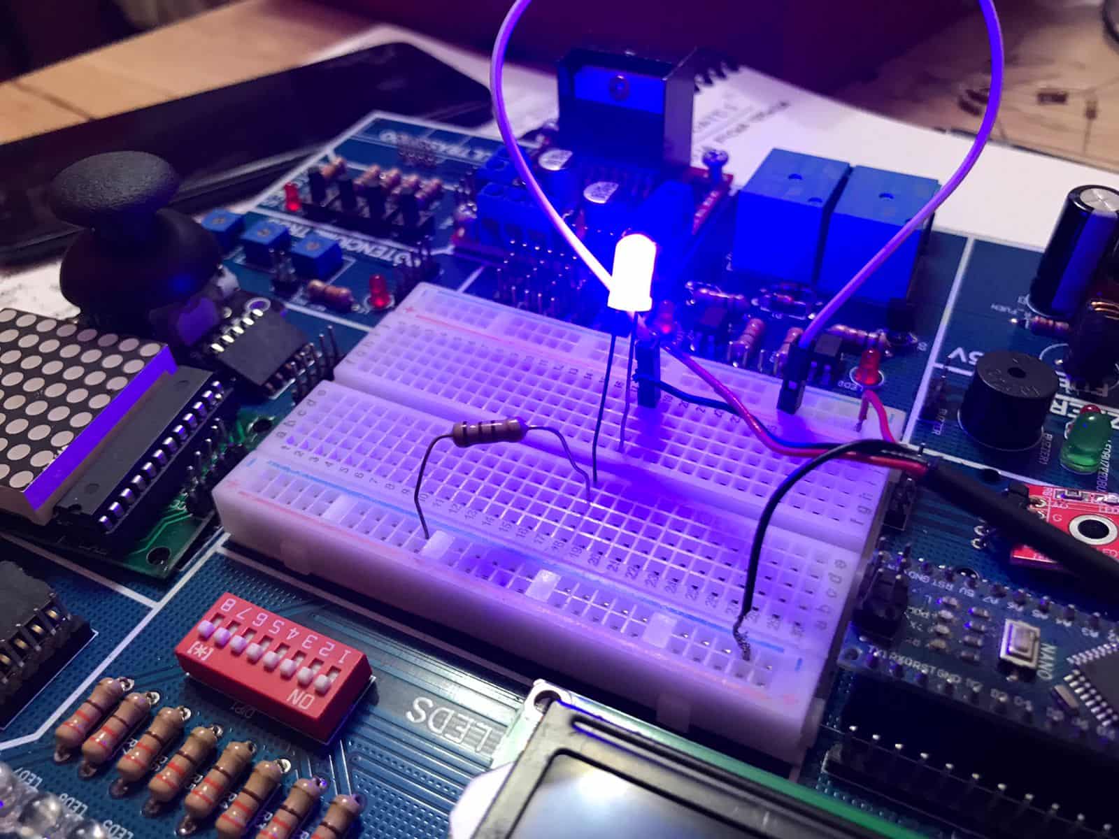
Blue LED
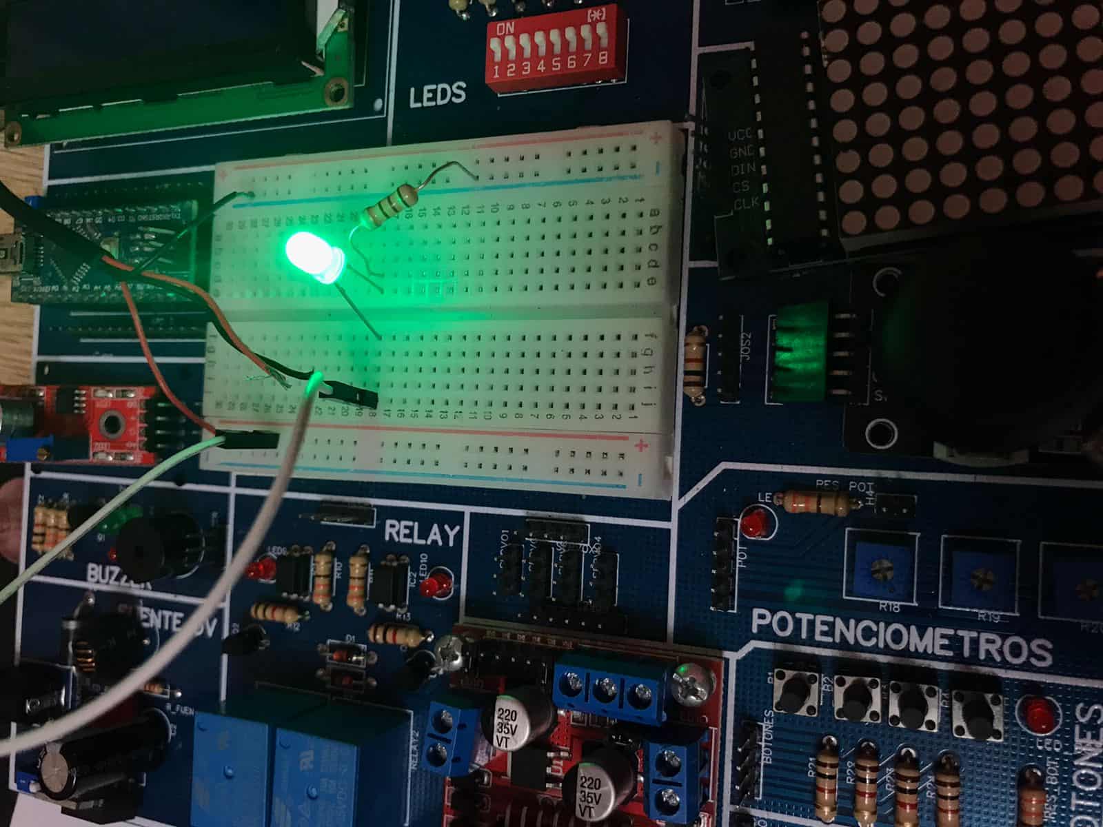
Green LED
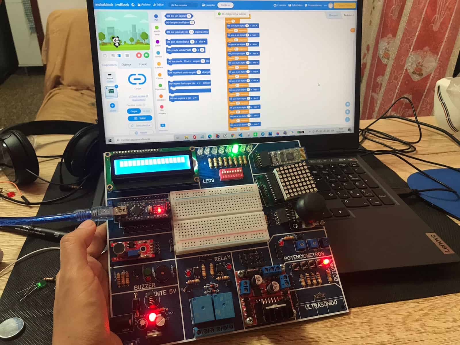
Programming with blocks
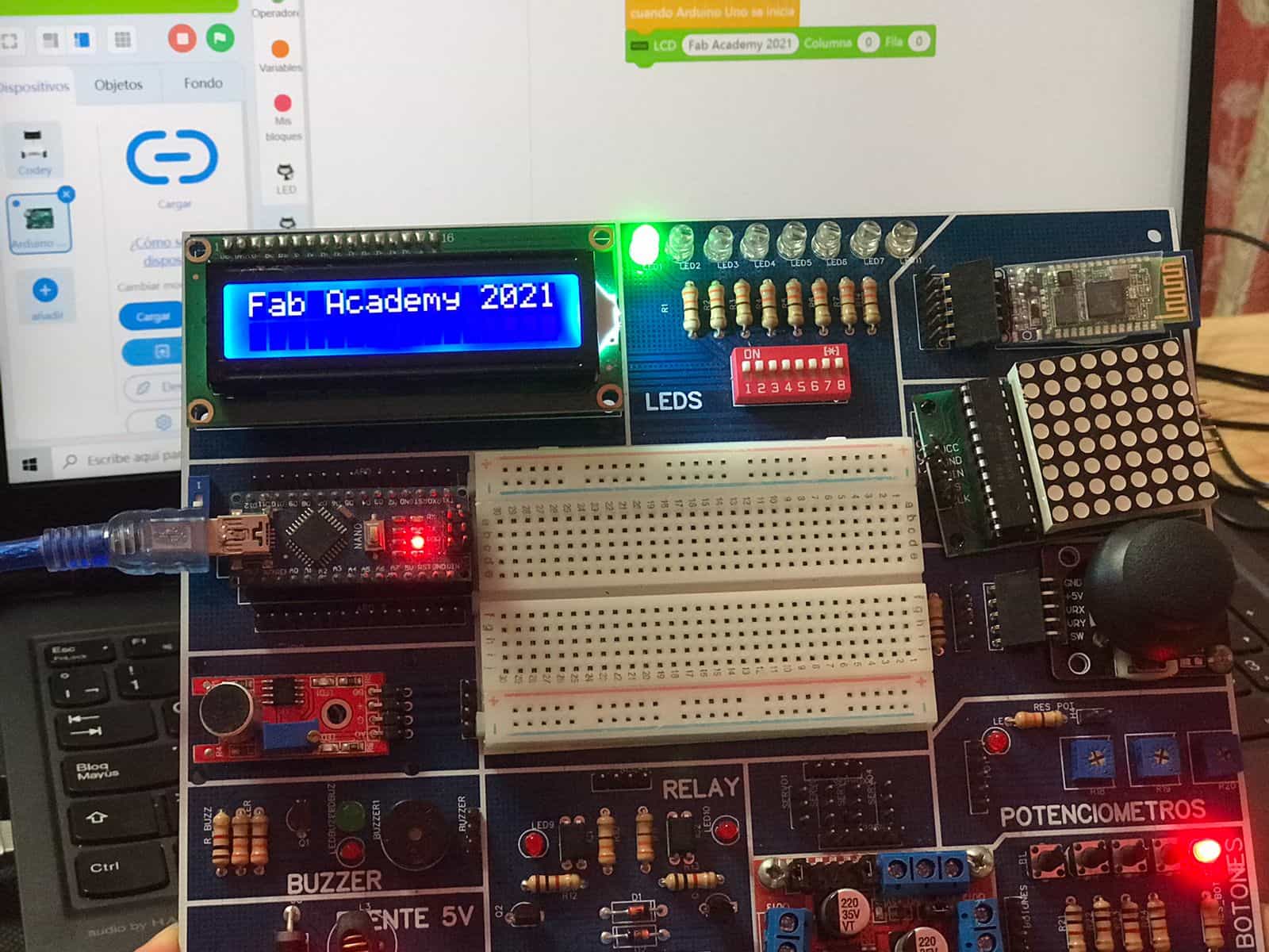
Programming with blocks
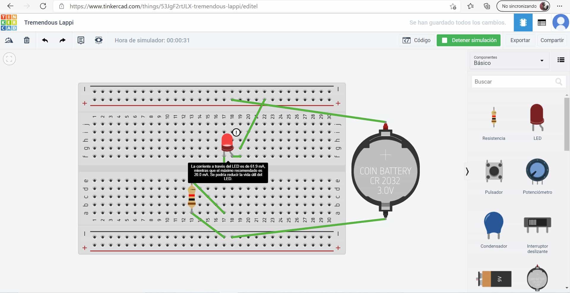
Exploring with a protoboard
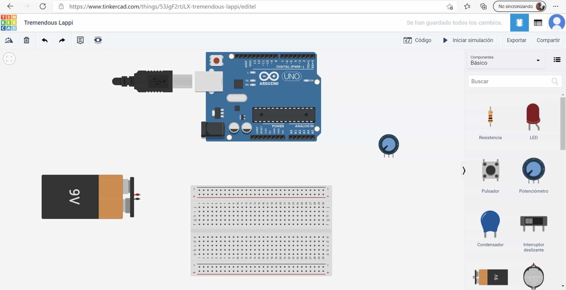
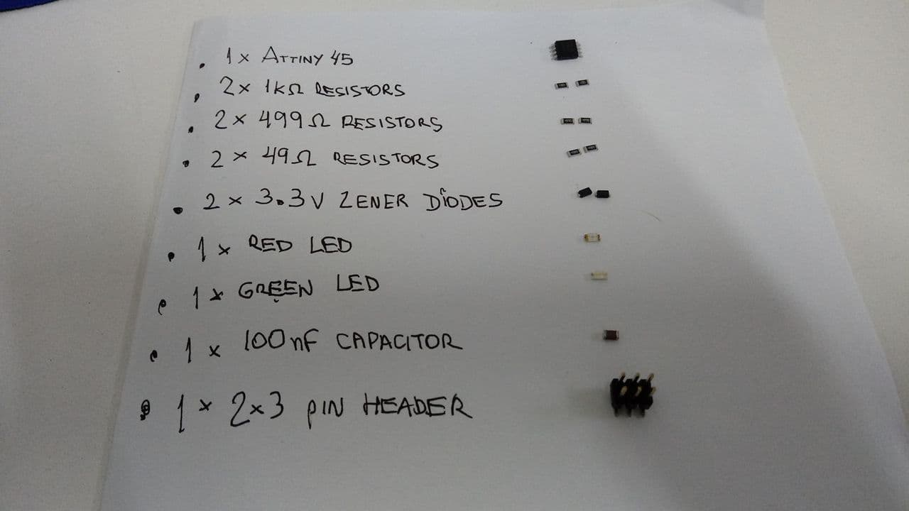
Looking for components
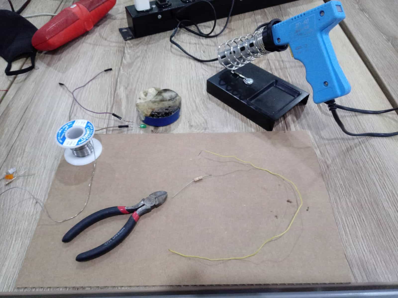
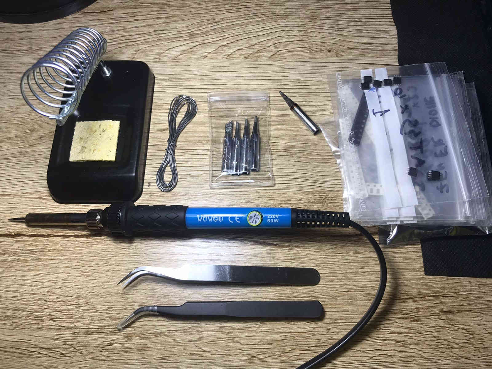
Instruments
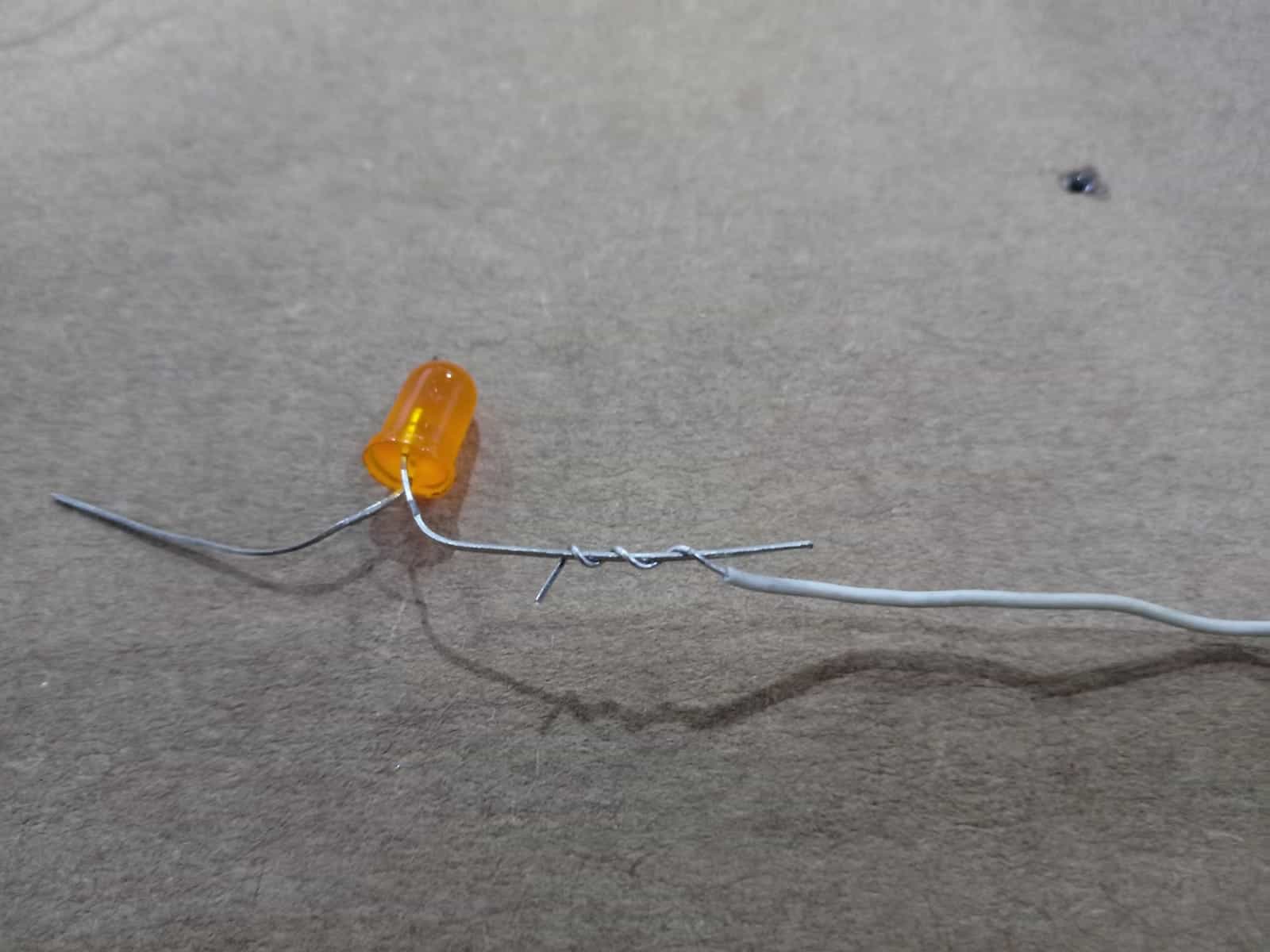
Connection of LED to cable
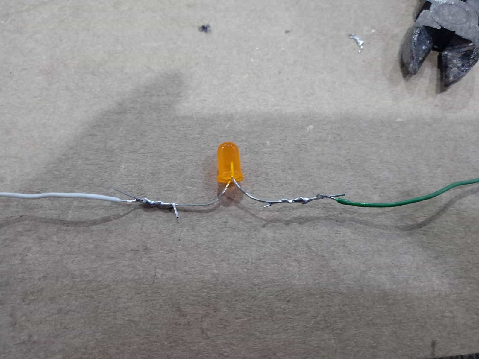
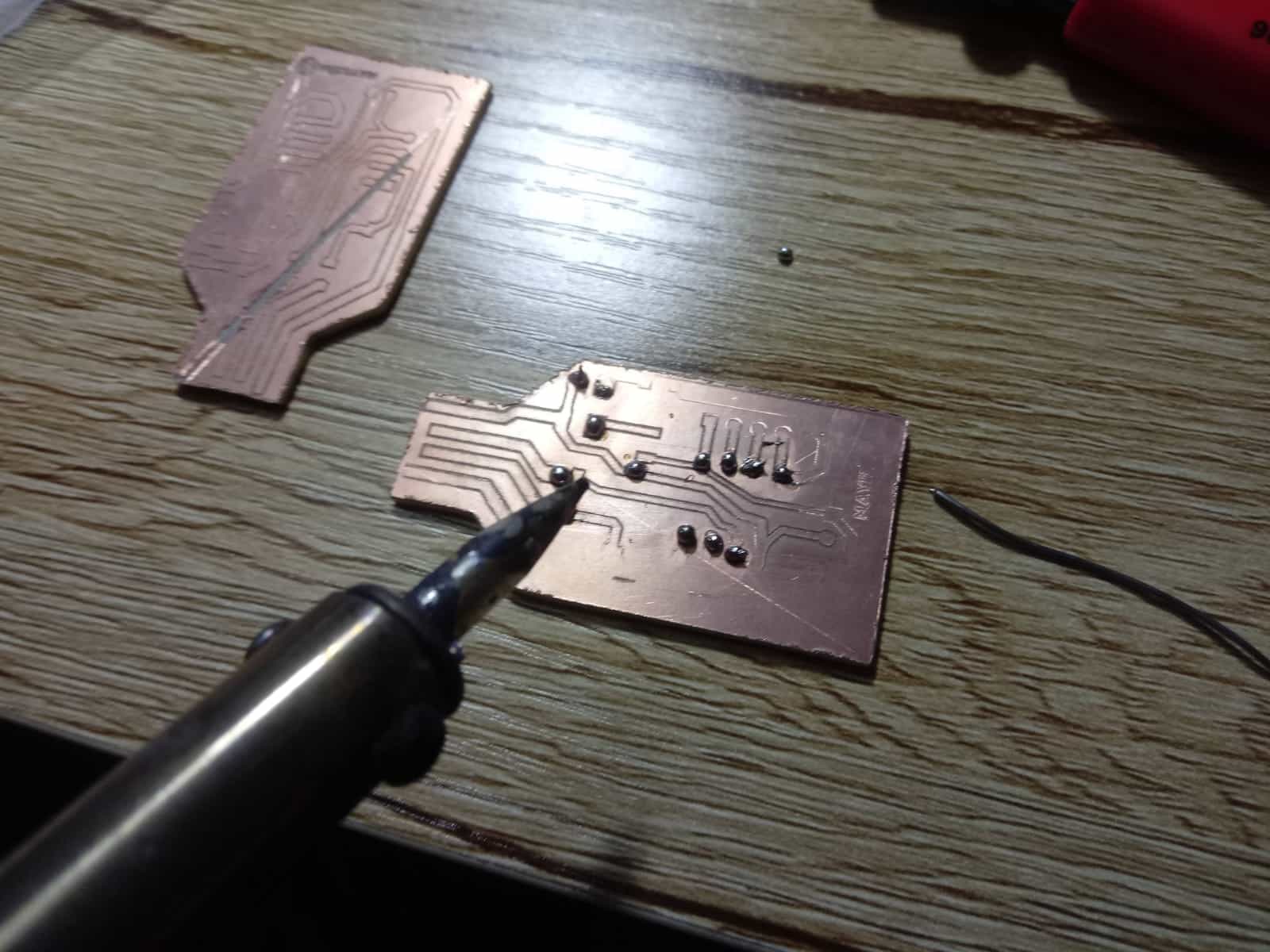
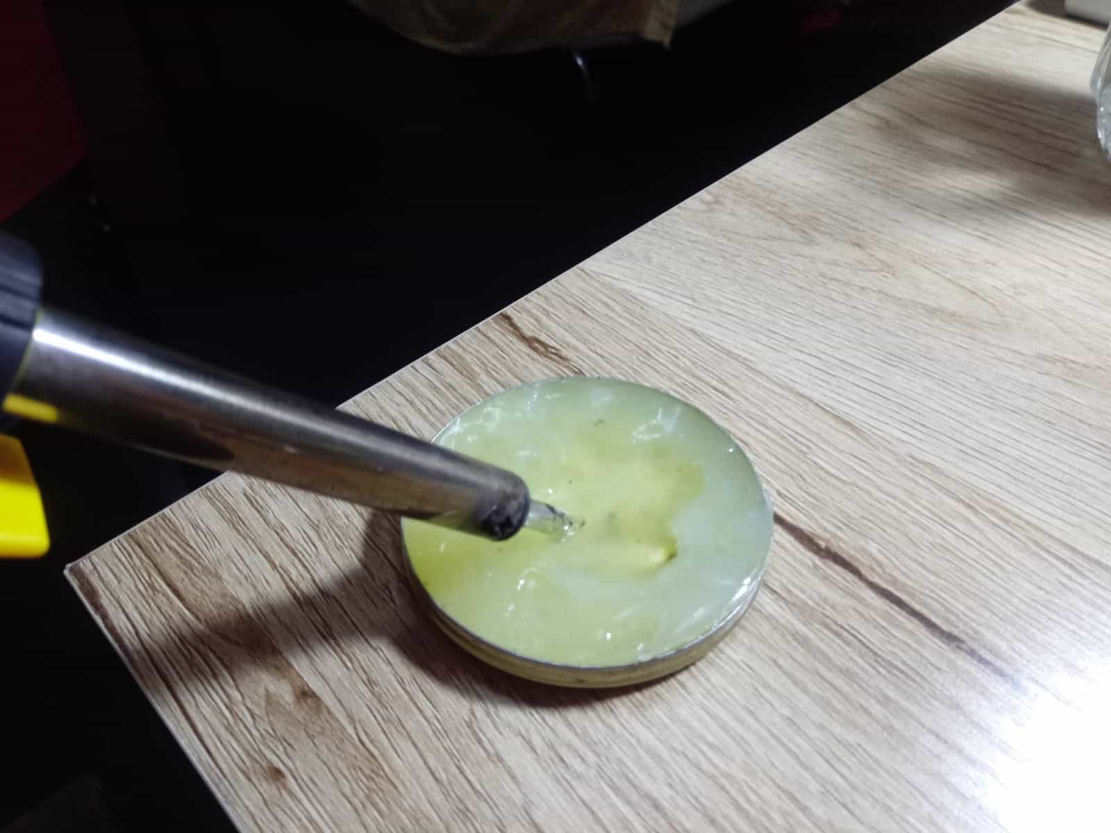
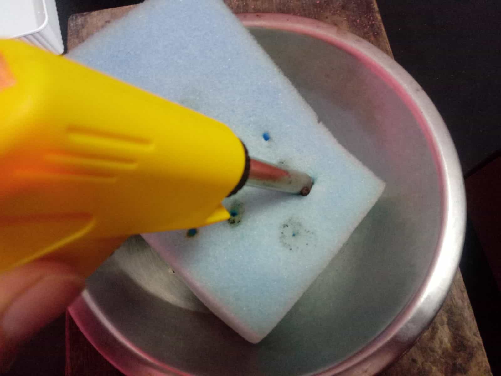
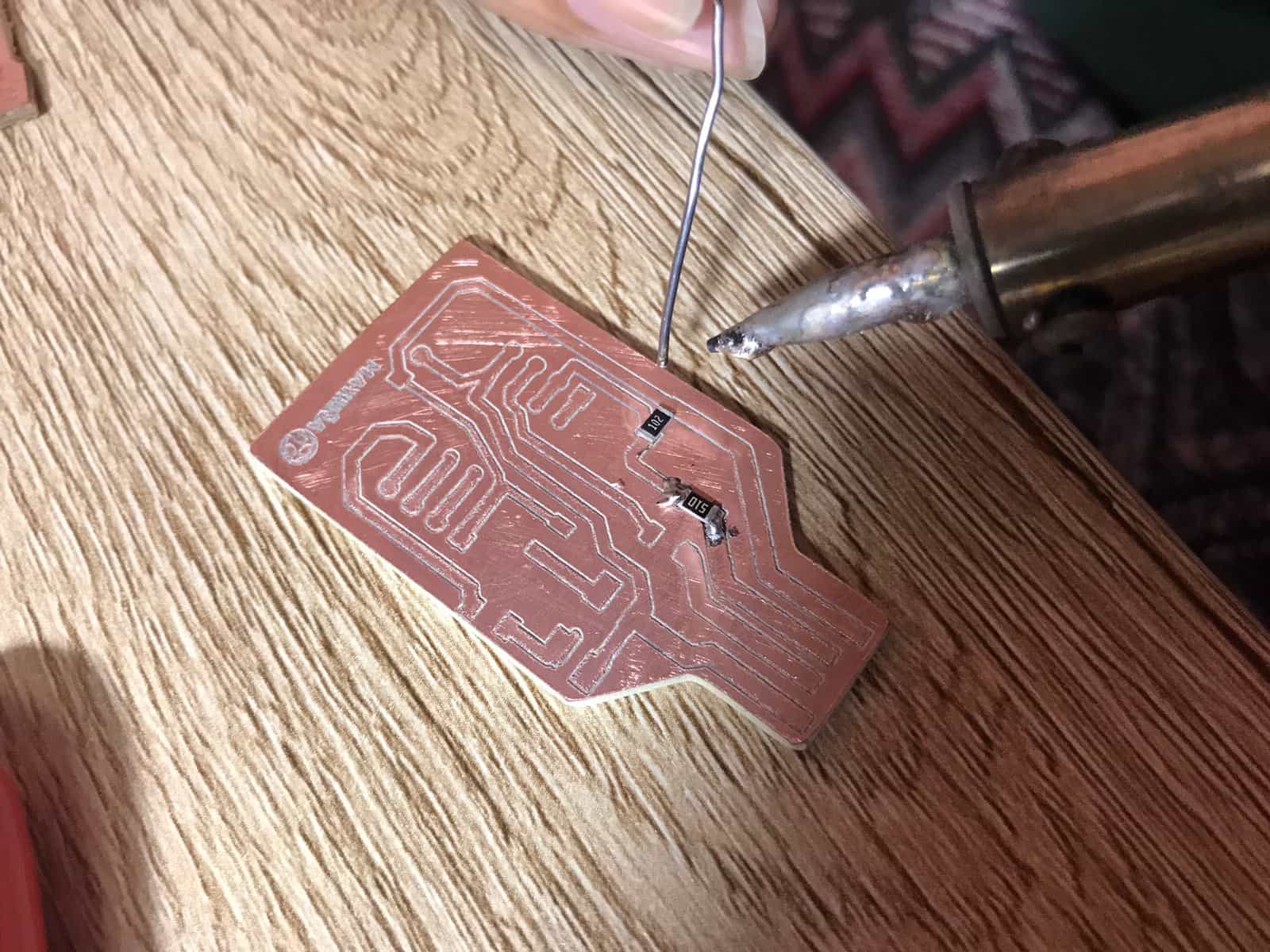
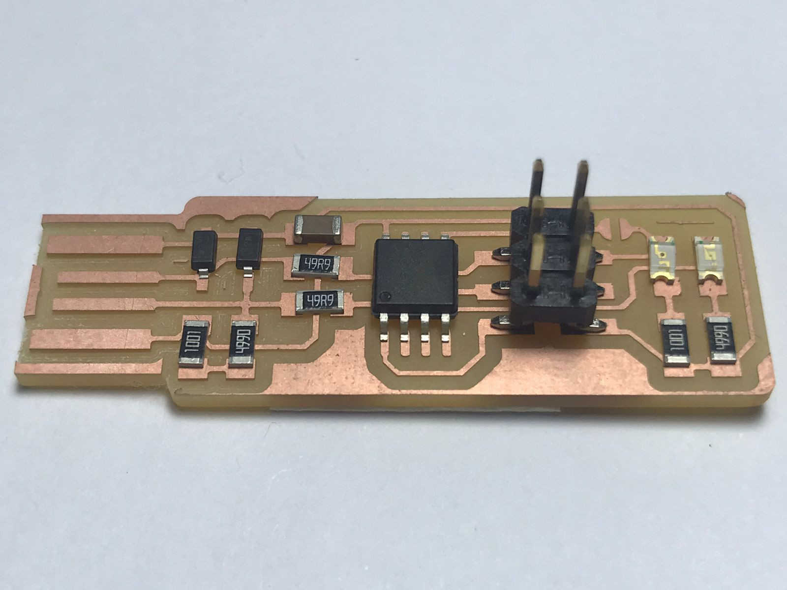
Soldering
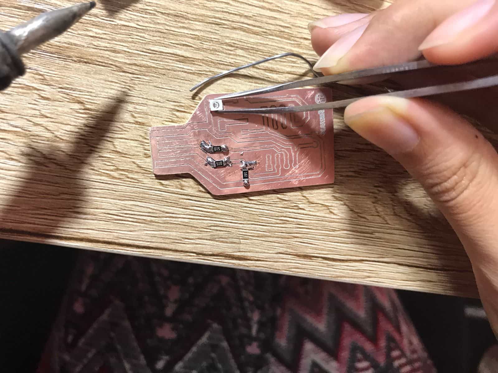
Soldering but with burnt wire
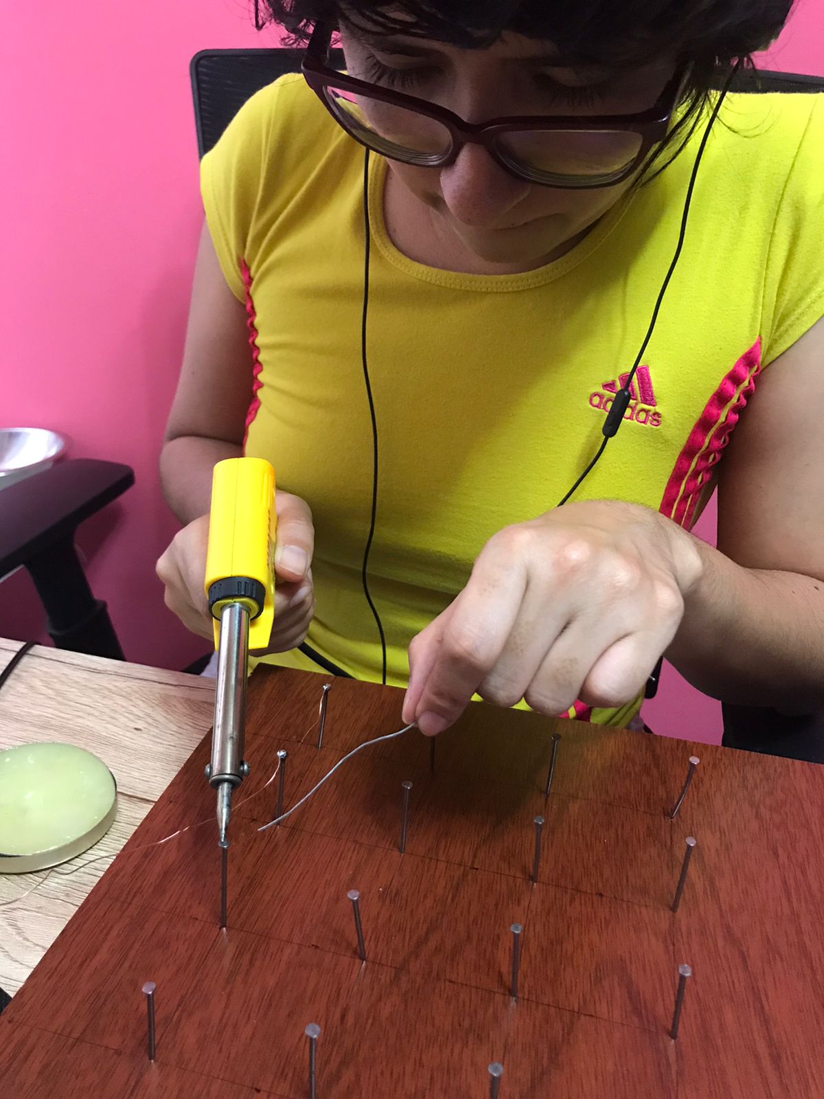
- Definitely with this first attempt I understood that soldering requires a lot of practice, it is important to reach a point of fineness in order not to burn the tin or the components due to the temperature of the soldering iron. Because of this and thanks to my friend Walter from Honduras I did an exercise that he recommended me. I got a melamine board, some nails and a UTP cable, I organized them every 5 centimeters creating a kind of mesh and soldered point to point the heads of the nails with tin. This exercise was very good, it helped me to understand the best way to place the solder and to have better precision. I highly recommend it, Thank you Walter! 🥰
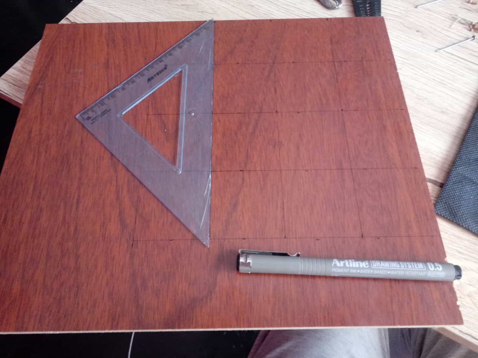
Organized workspace
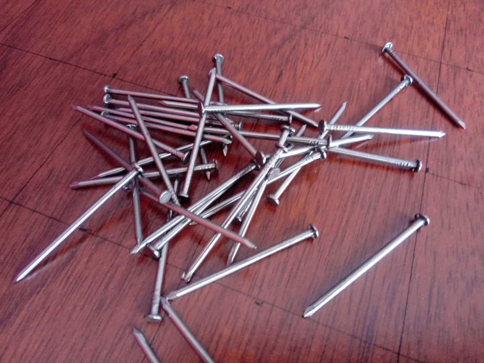
Keys
Practicing precision
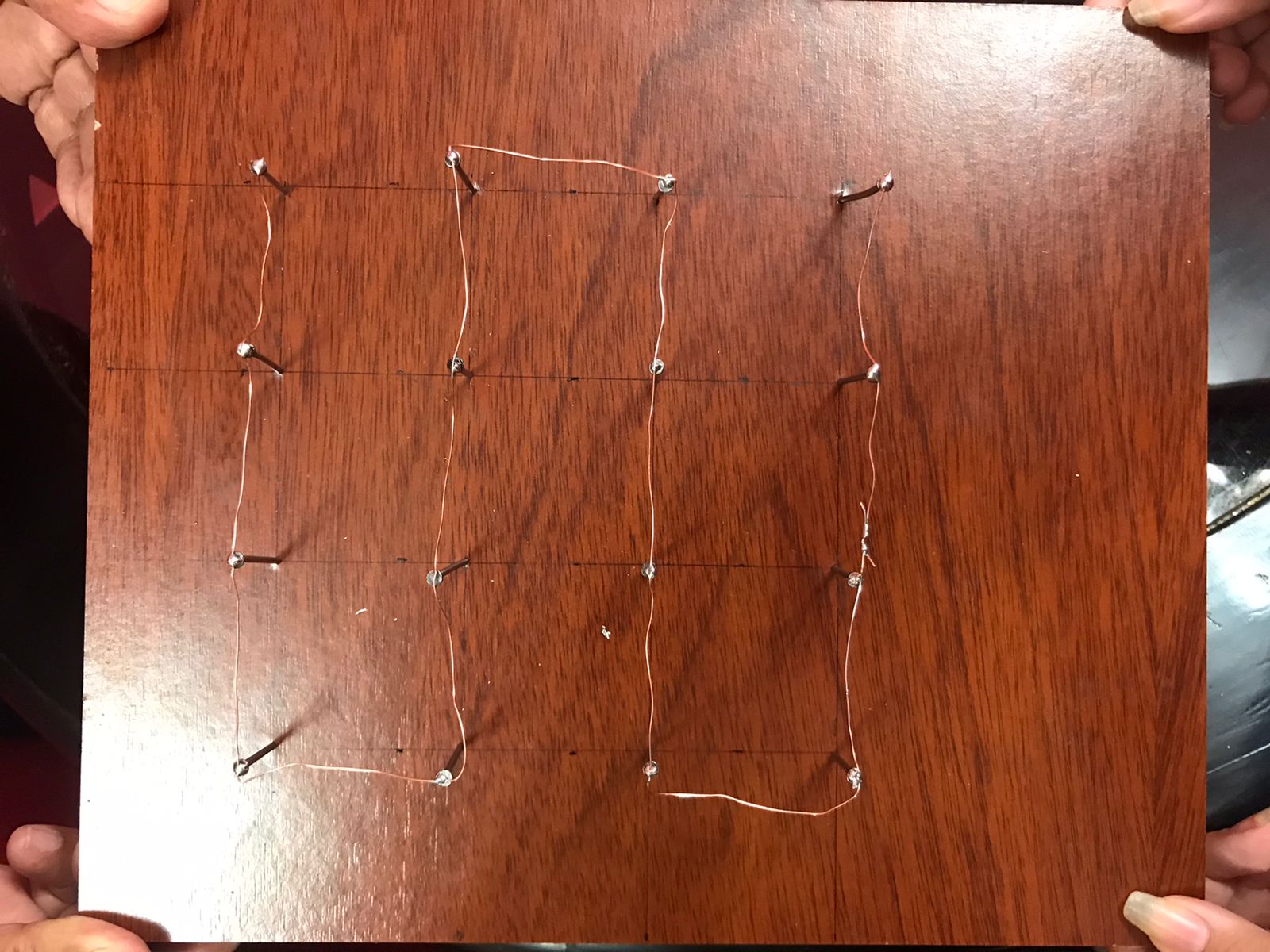
Final result
-Thanks to all these practices I felt more familiar with the concepts and components that we are using, for those who just have knowledge about electronics like me I will tell you that you must have a lot of patience but above all willingness to learn and to solve the challenges that you have in front of you. 💪
.jpg)