Difficult, stressful, frustrating and a lot of learning, that's how this week has been. I have the suspicion that as I write this today, Saturday March 6th, I have many things to resolve but that in the next few days before the following Wednesday I will have already overcome them. 💪 I still have a hard time understanding the electronics part but I recognize that with a lot of research and trial and error you can learn.
I am going to share with you my general experience and show the results of what was successful and what was not, especially the mistakes, if you are a beginner in the electronics area it will be good for you to read these explorations that I did, especially if you are a beginner but you do not have the facility to get the components or have the necessary machines to do it.
PCB - Mayriña
My experience
First step
Remembering week 4 of the Fab Academy(click here), thanks to those first explorations and those first investigations about the beginning or the basis of electronics I was able to have a better understanding of this process, this week we are asked to design our own board, solder it and program it. The steps to do it are many but the first thing you must have is the necessary components and the tools you are going to use, here is the list that I needed for my first test: ✔️
1. Cautin
2. Estaño
3. Pinzas
4. Pasta de soldar
4. Desoldador
What I got
Here in Lima I was able to get the necessary components in a store in the center of the city, they are not so cheap but not so expensive either. Thanks to my partner Hayashi Mateo we made a single purchase to avoid going several times so it is advisable in a pandemic context to avoid going out the least amount of times to get anything. In total I spent an average of 40 soles for all my kit for this assignment. 😃
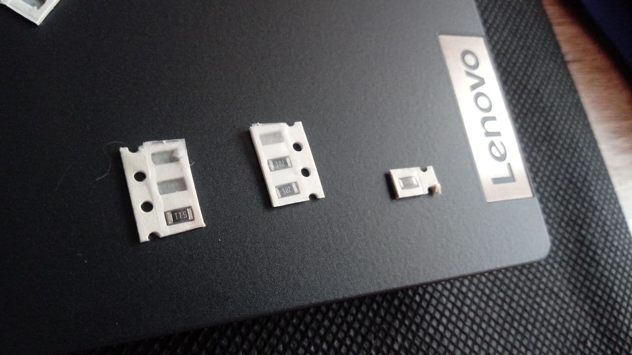
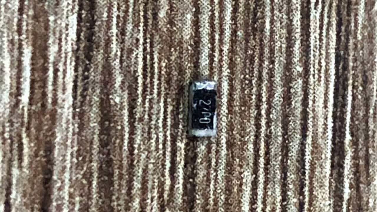
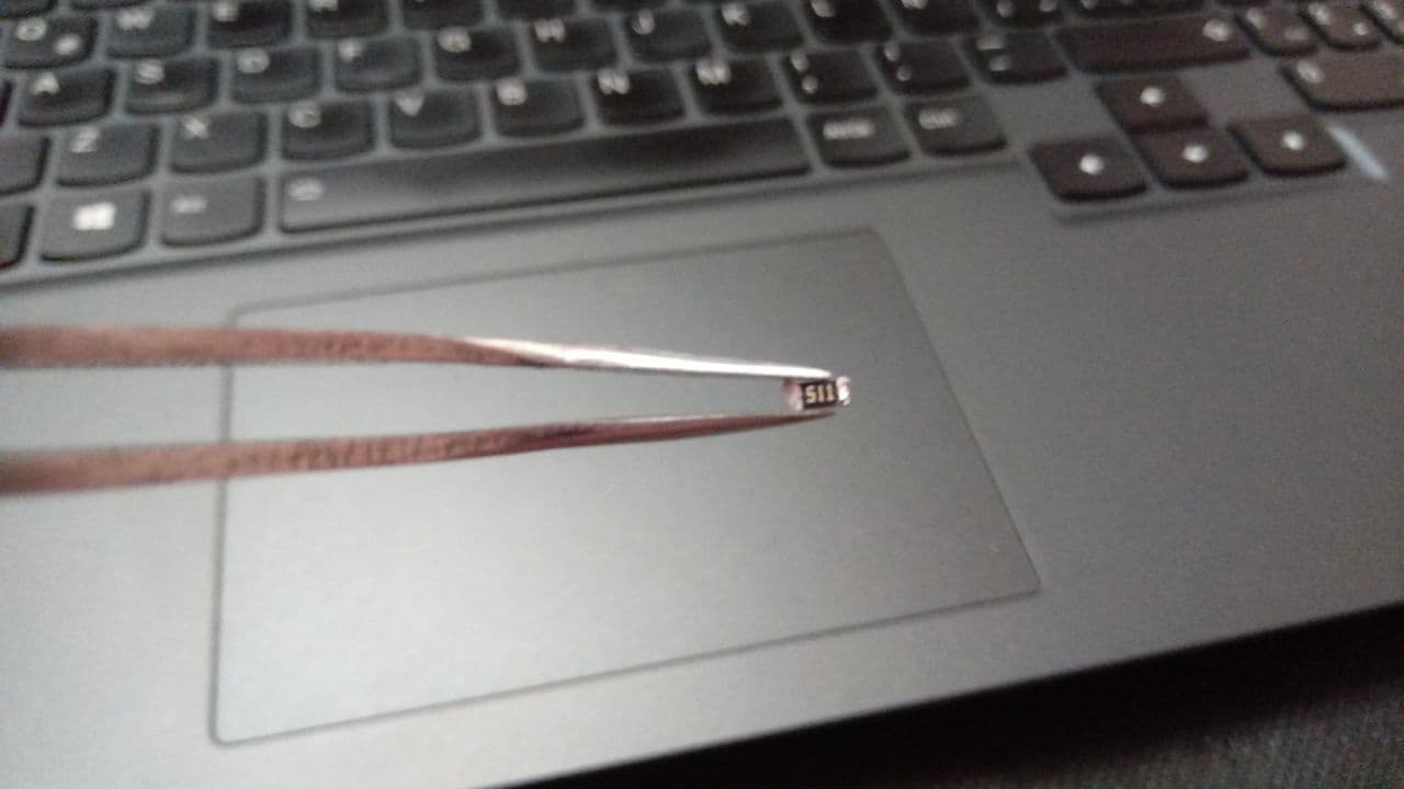
Resistors
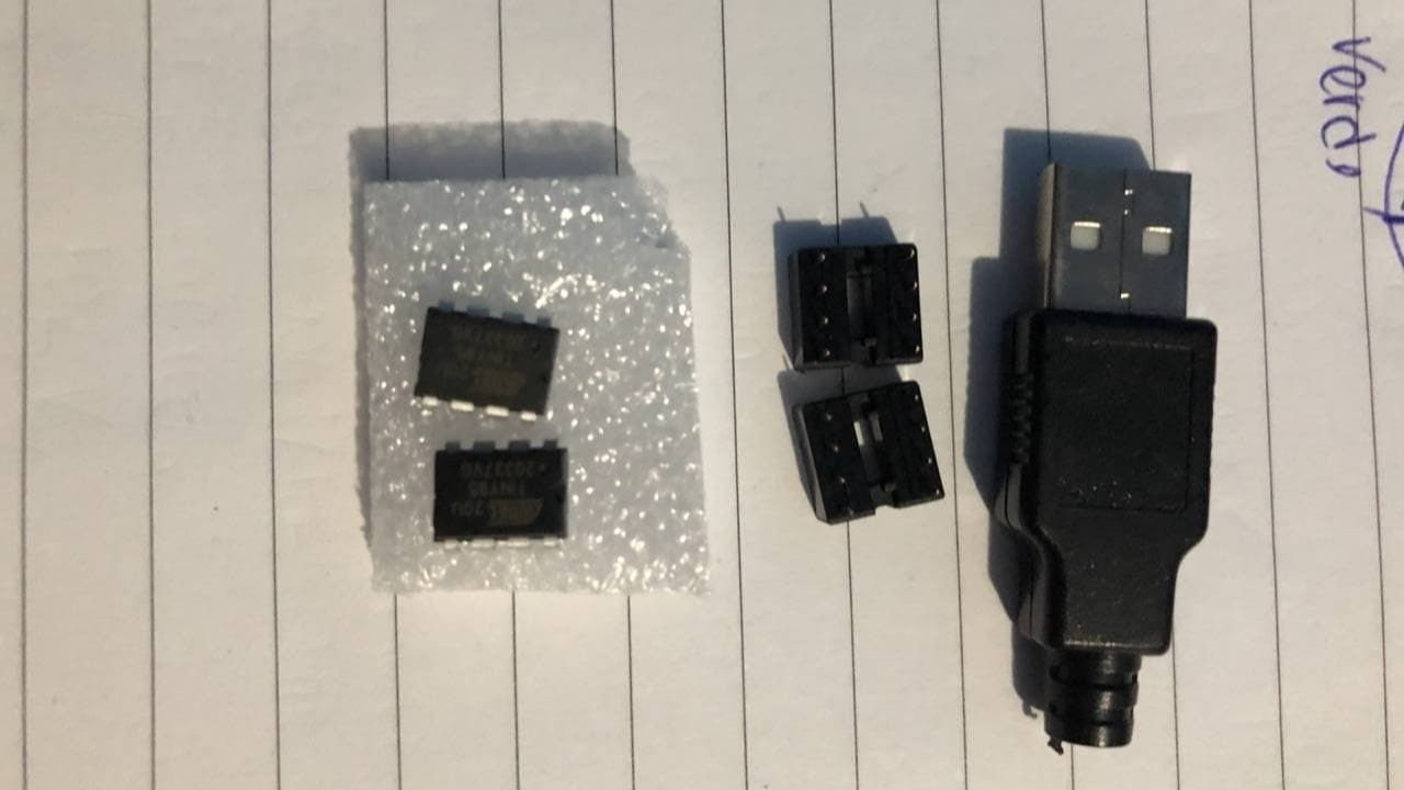
ATtiny85-Sockets-USB
First Assignment
Grupal Assignment
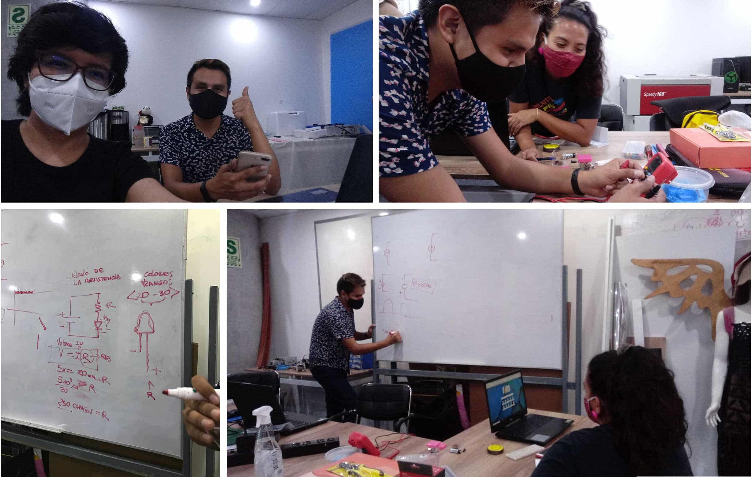
As a group task this week we are asked: Use the test equipment in your lab to observe the operation of a microcontroller circuit board. The first thing I want to share is that we don't have that equipment so we had to get creative. Thanks to the team we decided to look for affordable solutions to achieve this assignment, here I share with you how we did it. 💪
Working at Home and LAB
Grupal
This week we were able to work in our laboratory, thanks to the fact that the quarantine is no longer in force and thanks to the care that we all take when working, this is very important to keep us safe since the contagions in Lima - Peru have increased a lot about the coronavirus.
To understand the group assignment we got together to investigate and understand the importance of what we were doing, we put together a plan that helped us to organize our time to be able to comply with everything required, it is fun to work with this team, I am very happy to do my research with them. 🥰
Super Team Fab Lab Perú.
Exploring
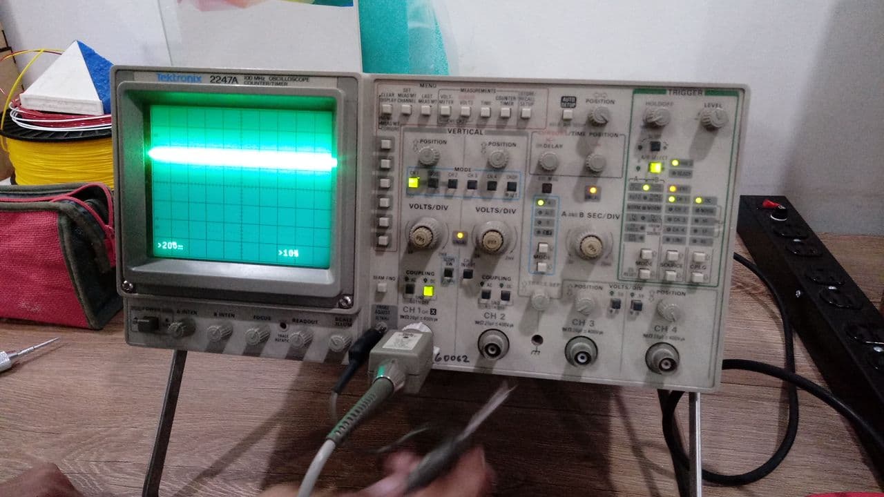
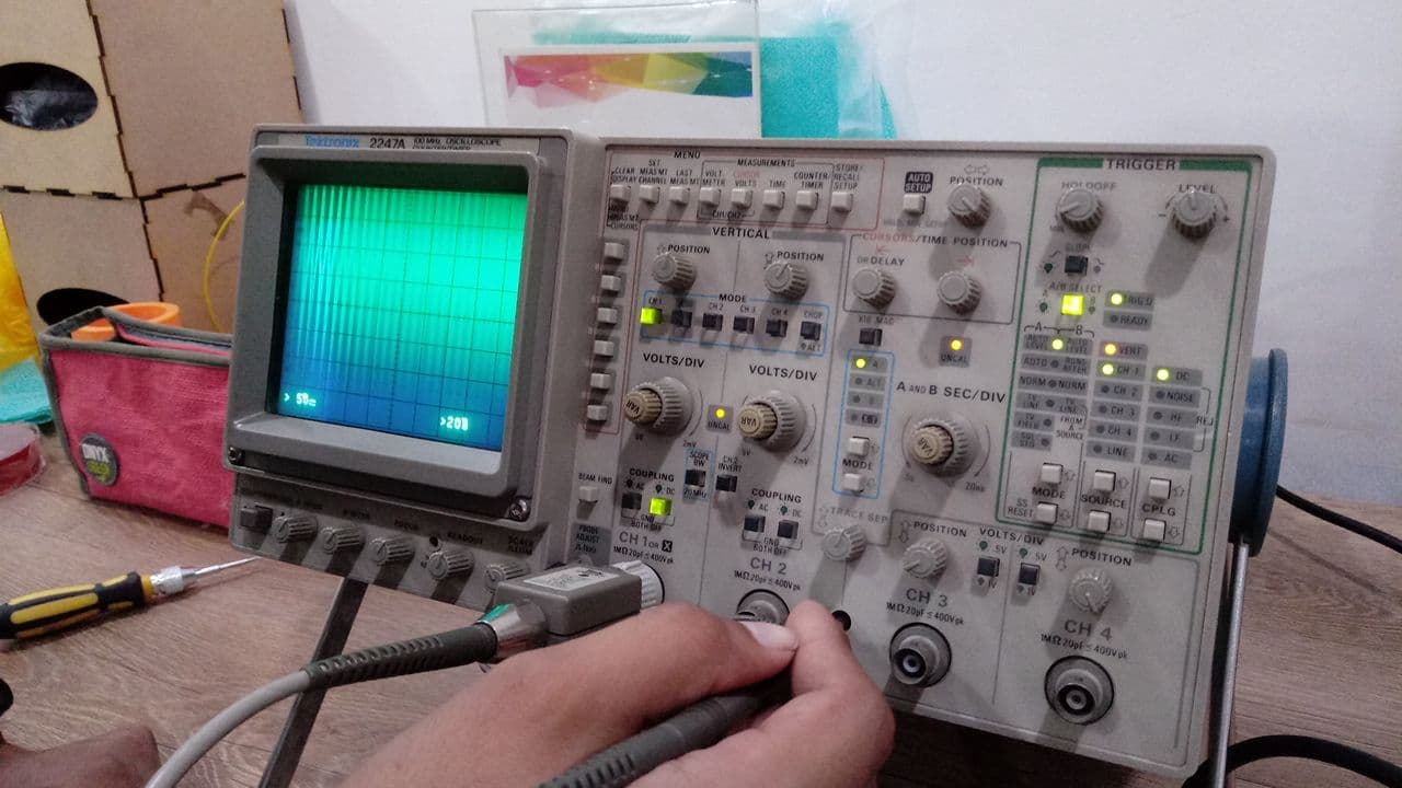
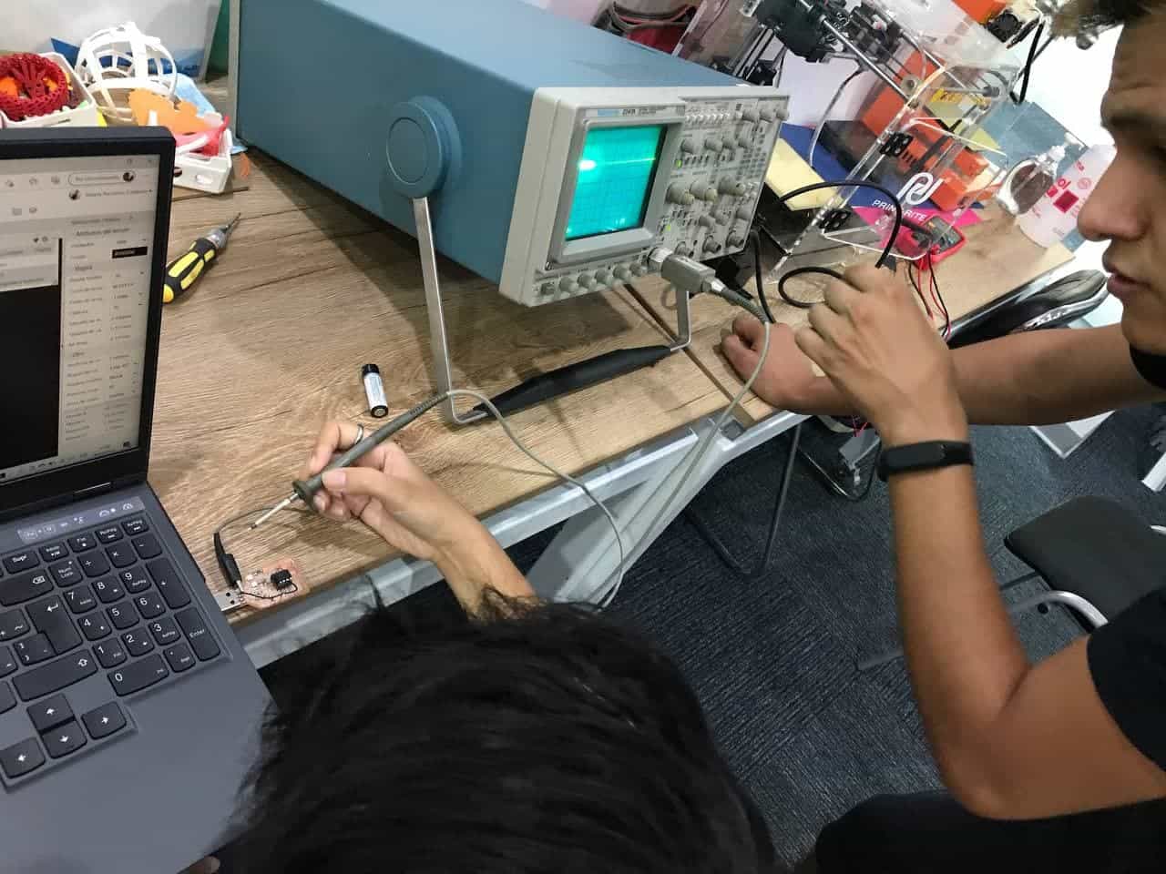
Thanks to the support of a classmate's parents we got to know an old oscilloscope, I had never seen one before and even less such a big one, it was very interesting to know how it works and how to manipulate it, unfortunately we could not complete our task because something was wrong with its operation, but it was still a nice experience.
Oscilloscope
Oscilloscope
Trying
Trying
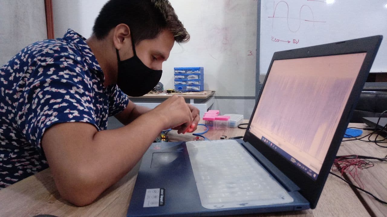
In the lab we got together to make an oscilloscope. An oscilloscope is an electronic display instrument for the graphical representation of electrical signals that can vary over time. It is widely used in signal electronics, often in conjunction with a spectrum analyzer. Thanks to our colleague Hayashi Mateo who is an Mechatronics engineer we were able to solve the assignment together, the only thing we needed was an ARDUINO UNO and a laptop to be able to do the test, the only restriction was that it could only recognize up to 5 volts, anyway it was interesting to see how we can solve something in a homemade way despite not having a machine. 👏
Working
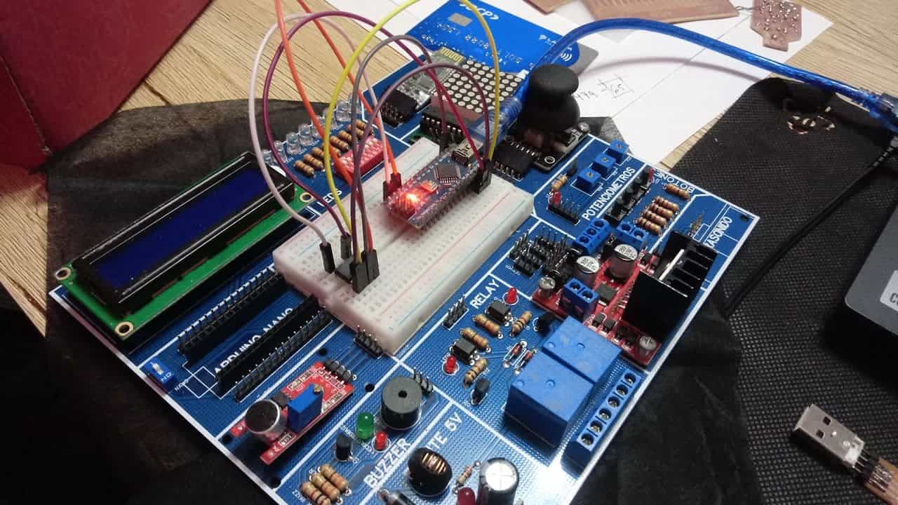
As a first step I needed an arduino nano, some jumpers, my board and the help of my mother and my sister, they supported me in holding the wires to show the video you will see below. 🥰
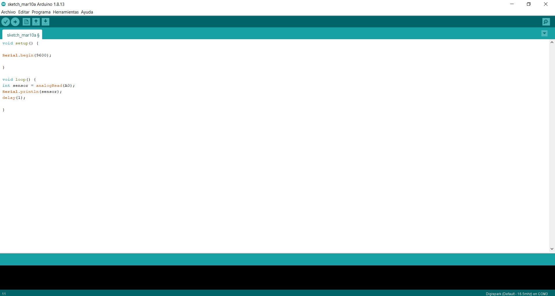
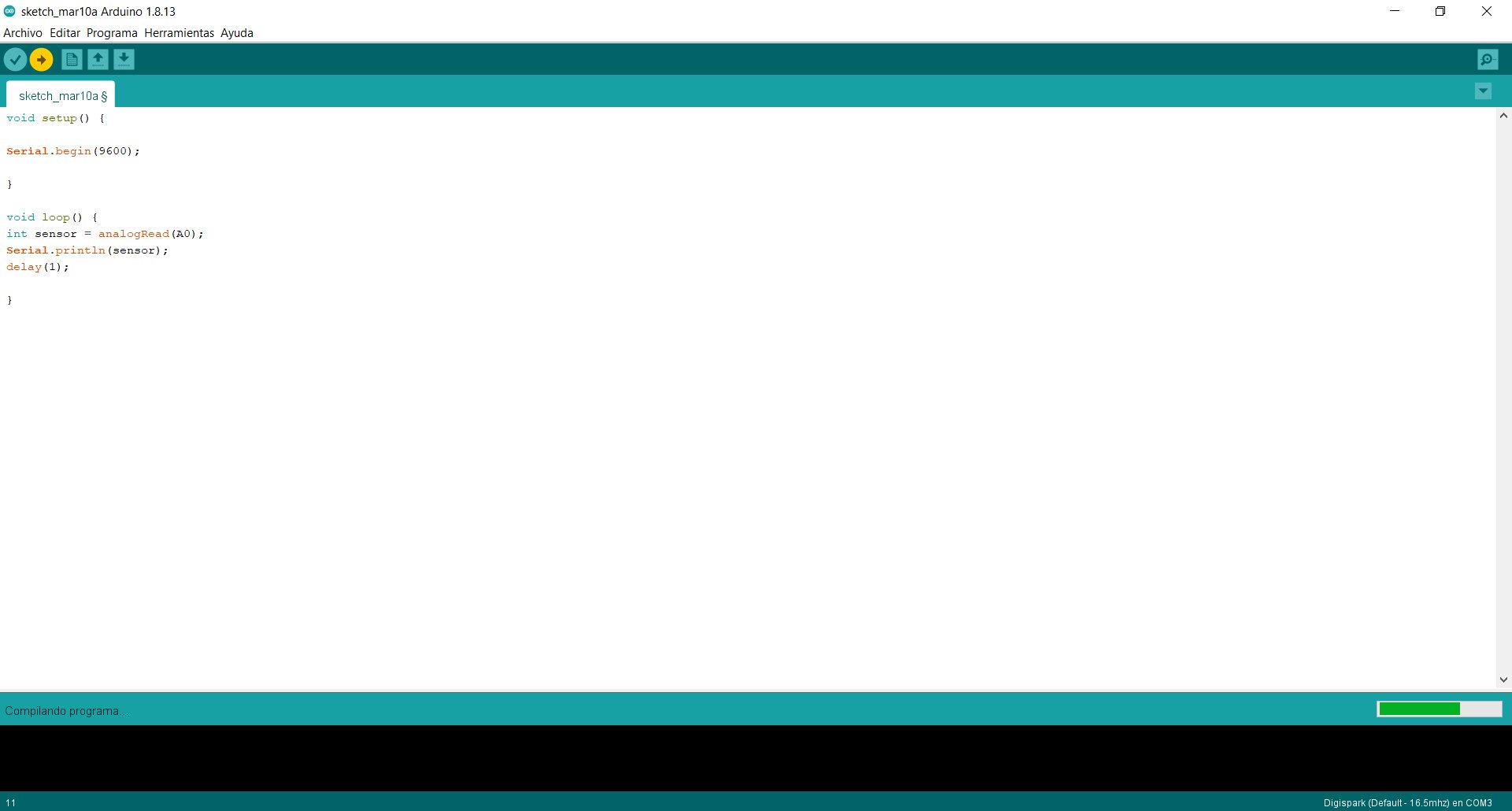
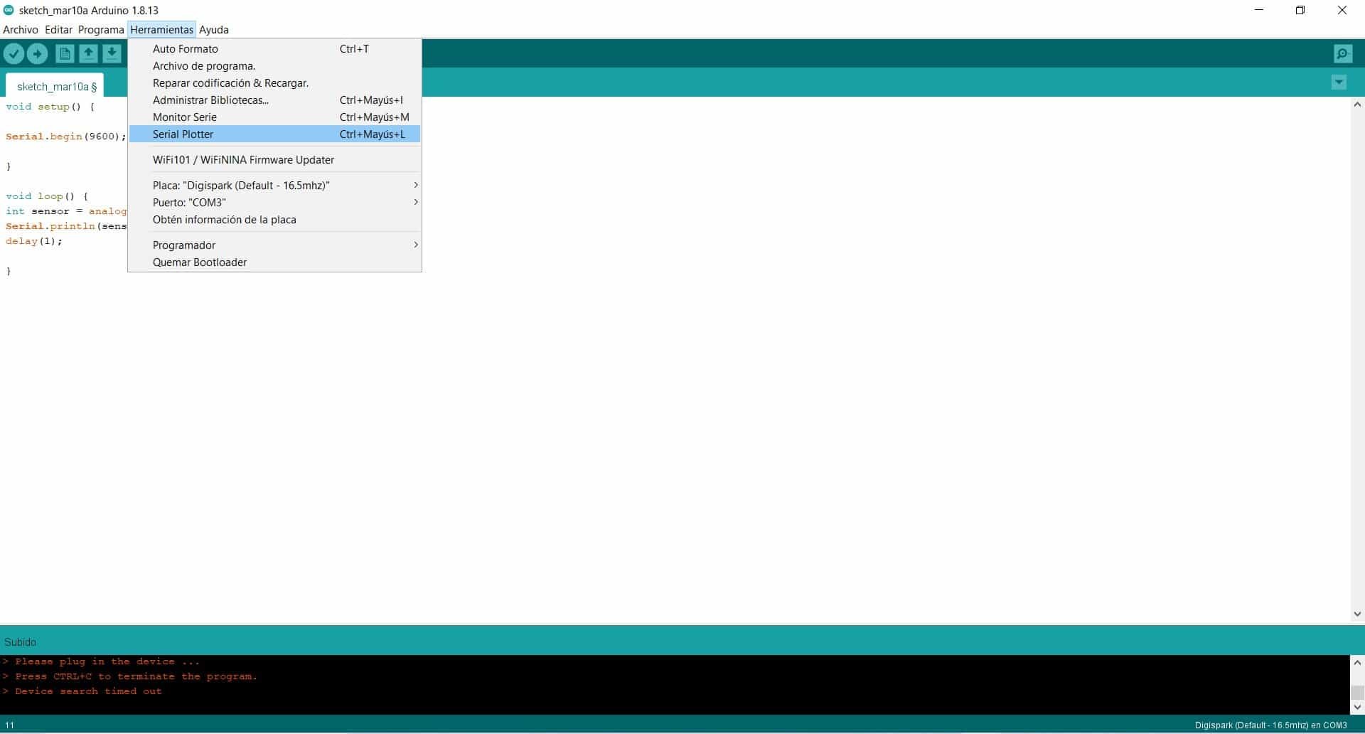
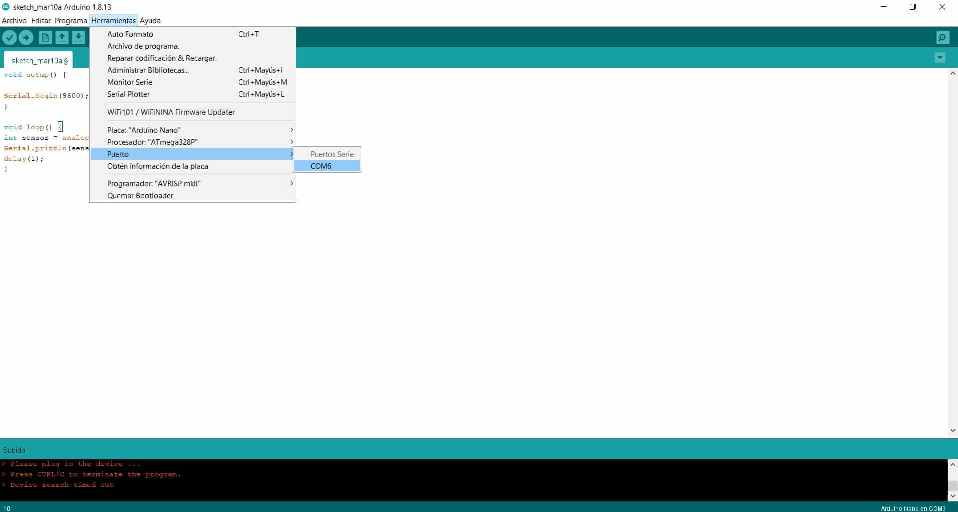
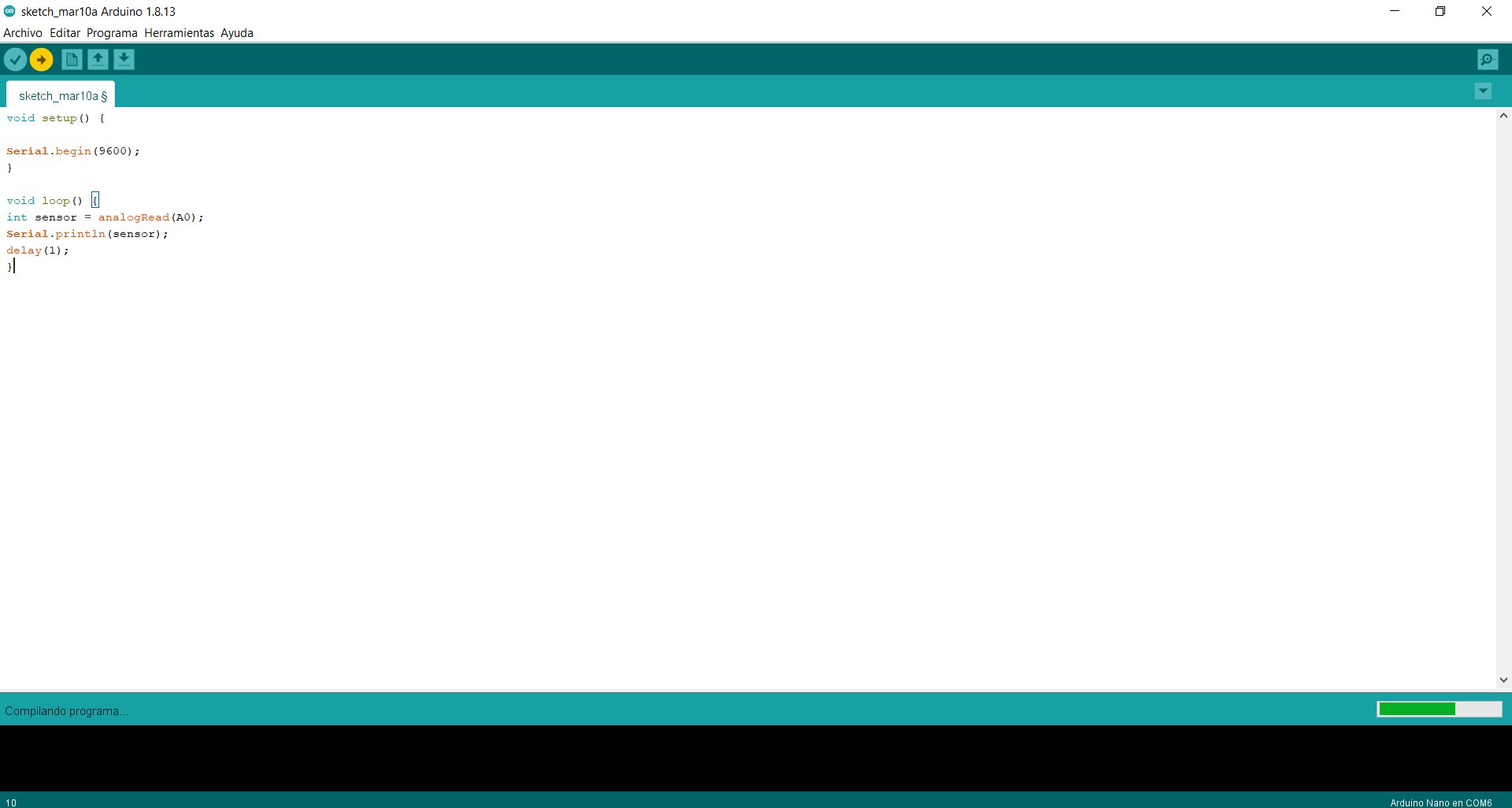
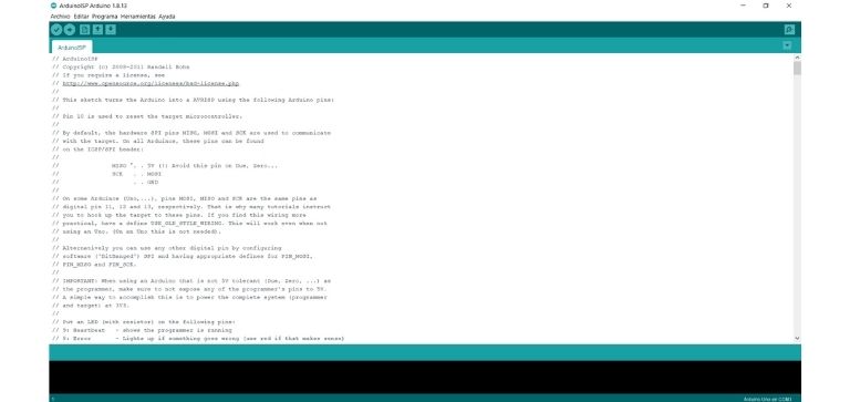
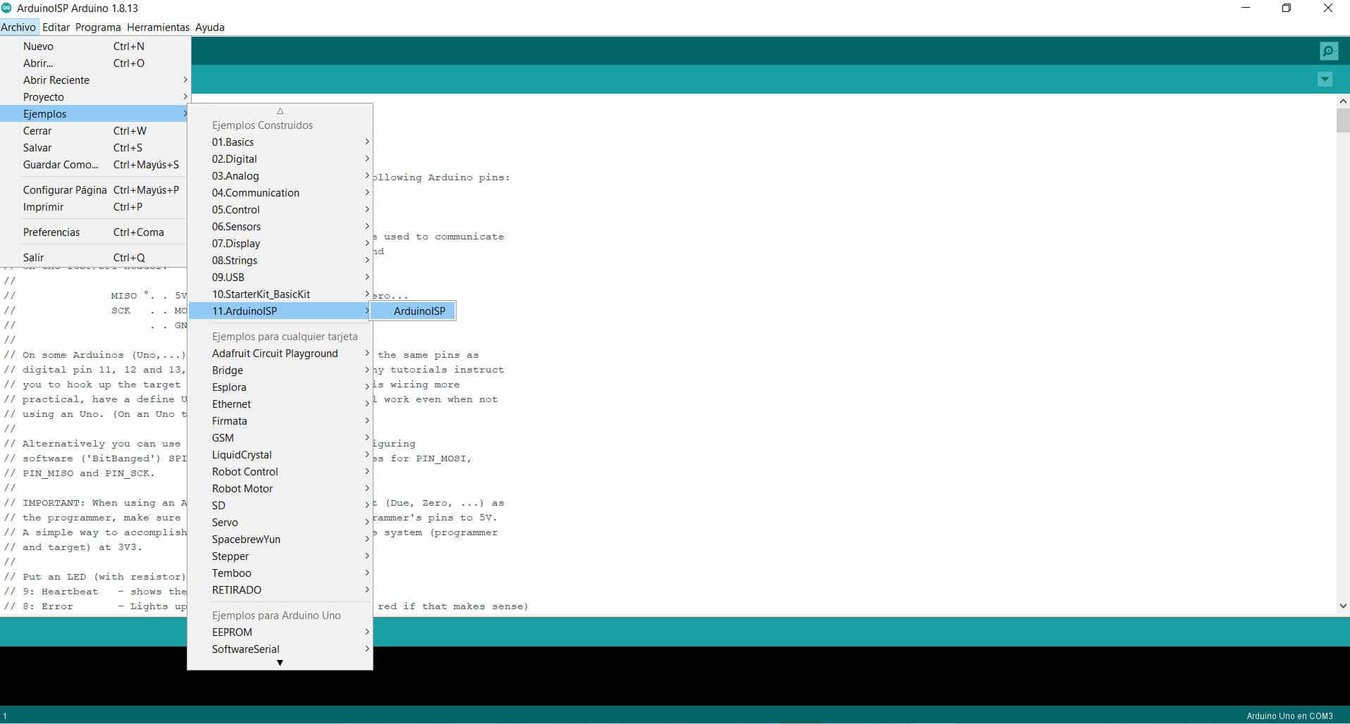
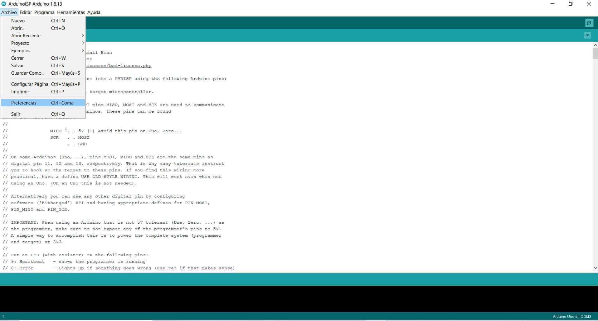
To get that graphic on the screen I used the Arduino ISP, this is a program that you can download from the official Arduino website. (click here) The arduino ID has 3 parts, global part (sensor), void setup (pins - serial) and void loop (functions that are going to be repeated). As I need communication between my display and the arduino nano I activate the serial function, bi-directional communication, then I used a code in the three parts that I will show in the pictures.
Coding
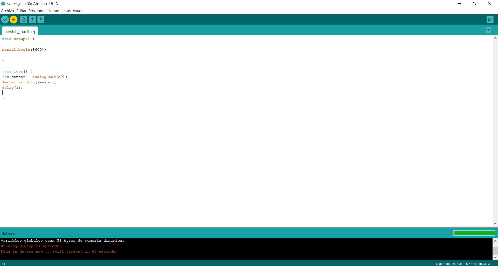
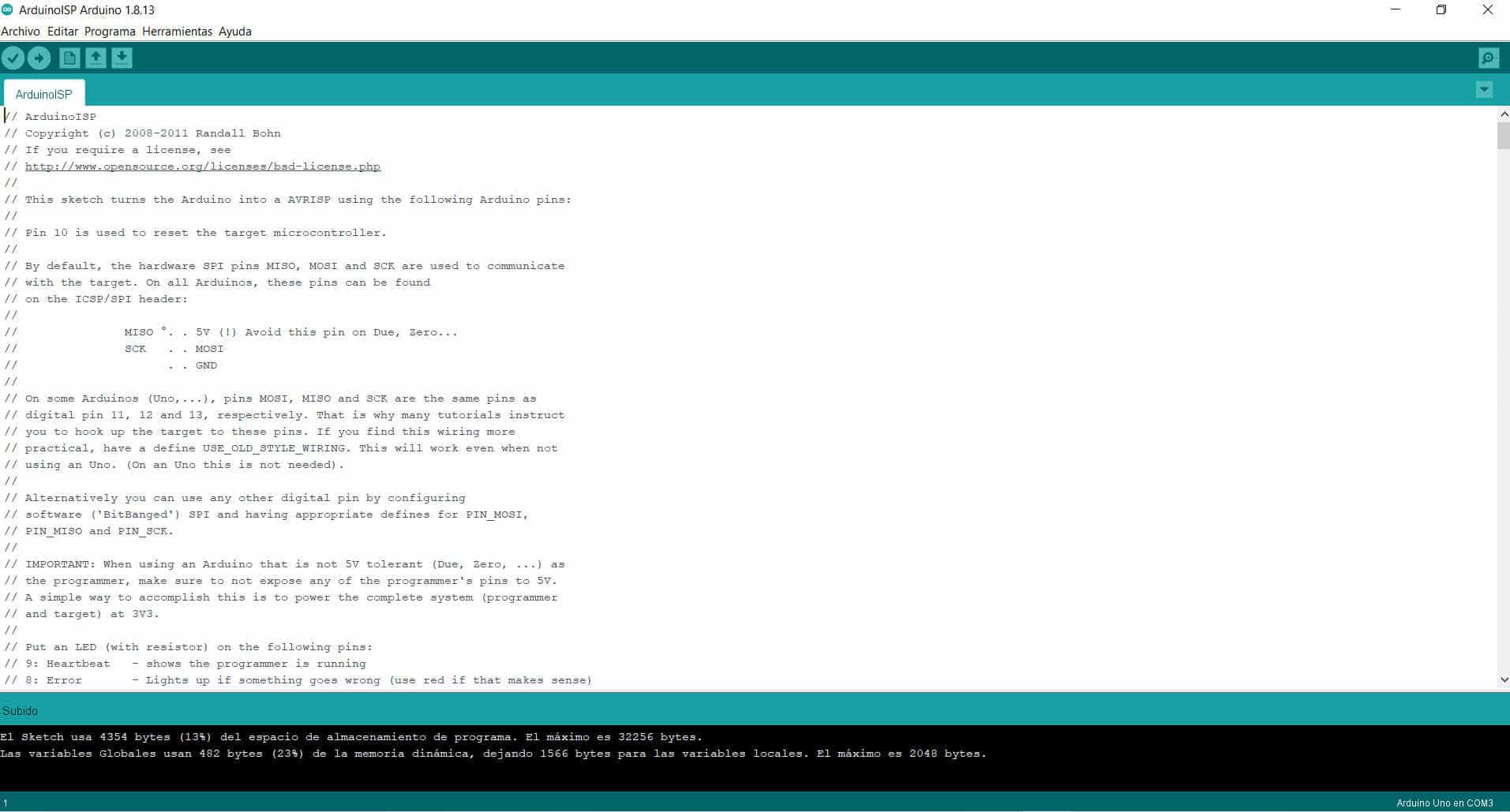
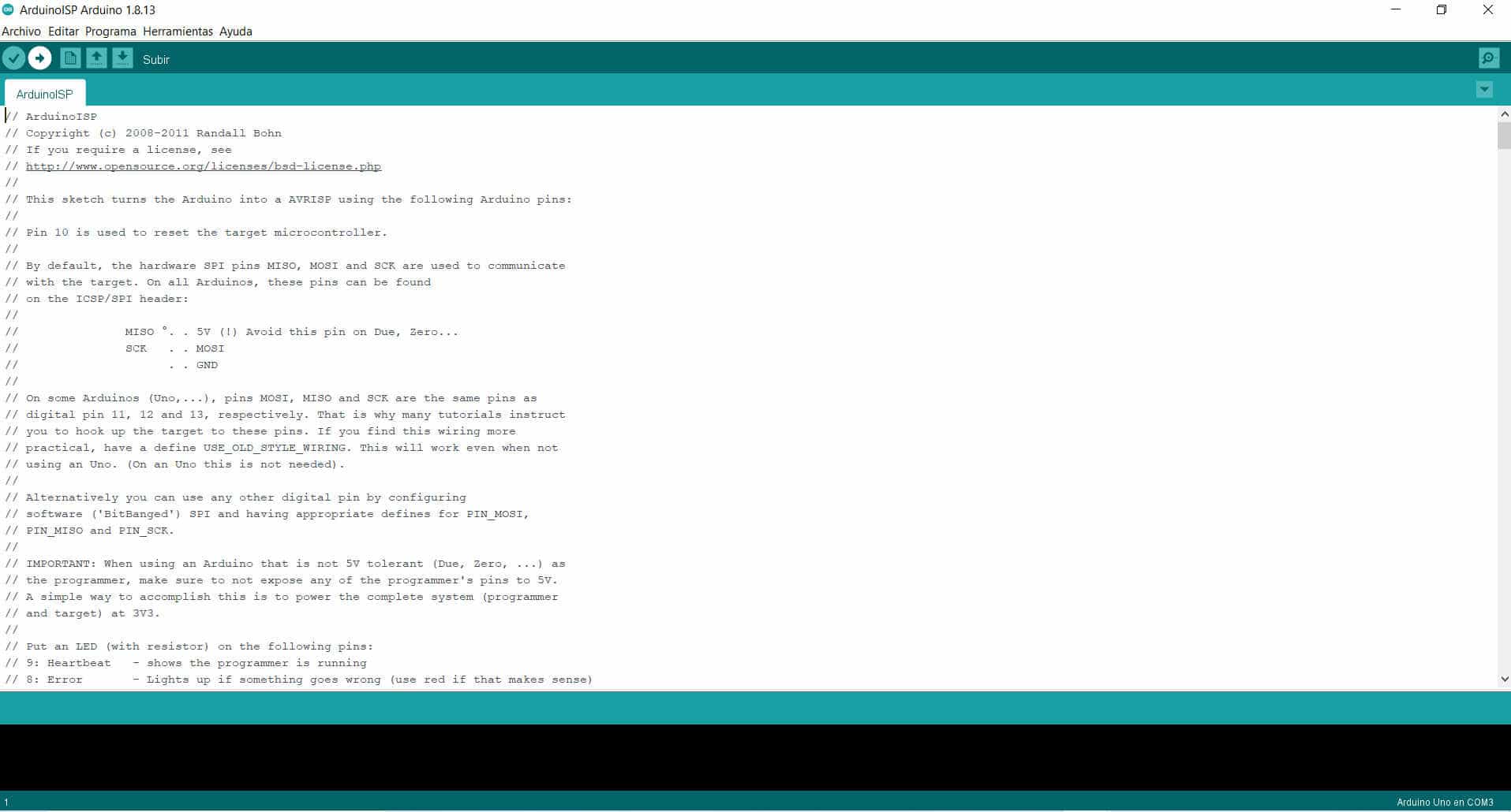
Uploading
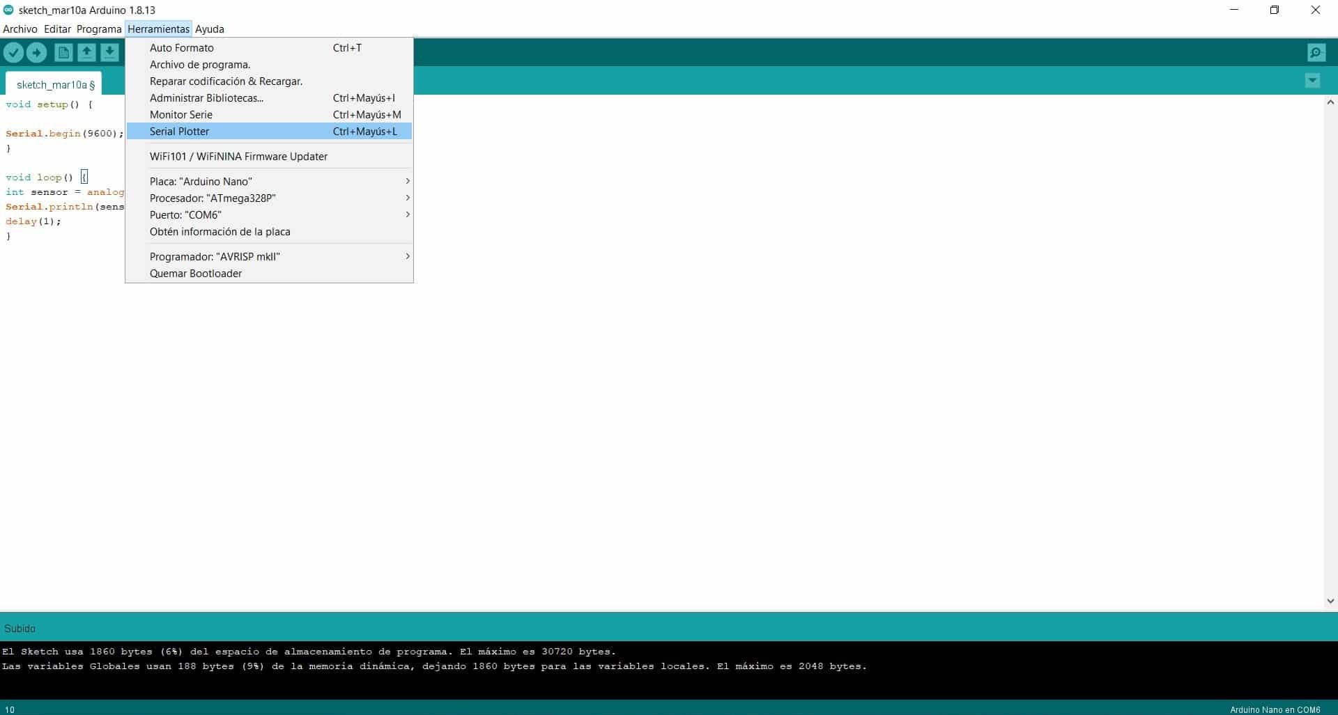
Serial Plotter
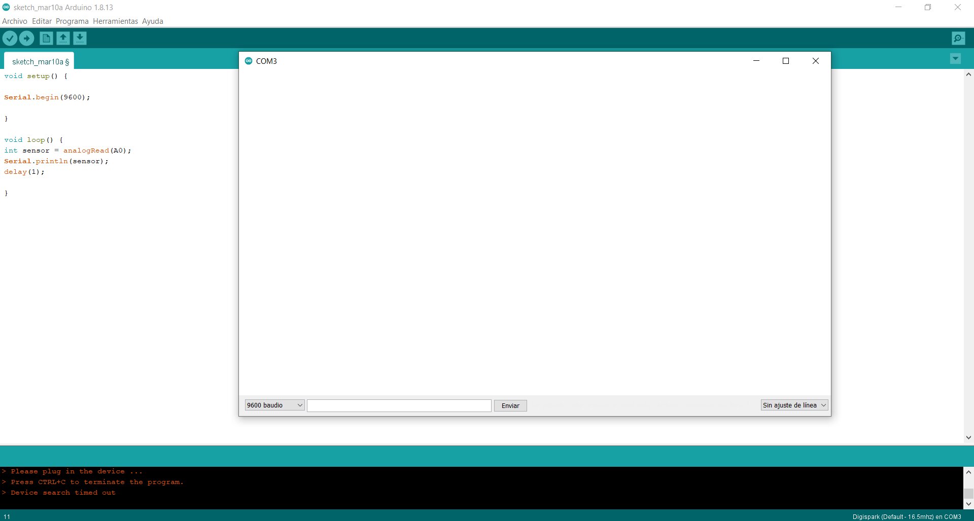
New window
Serial Plotter
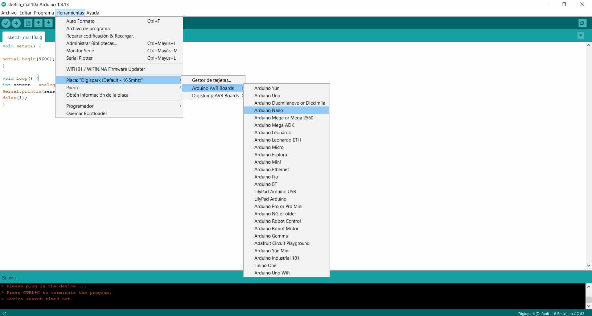
Arduino Nano
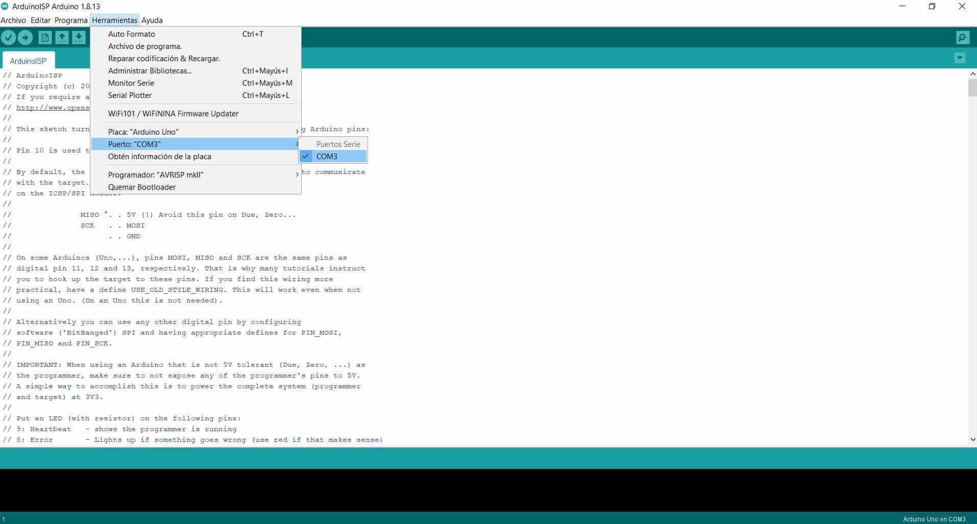
Puerto
Uploading
Serial Plotter
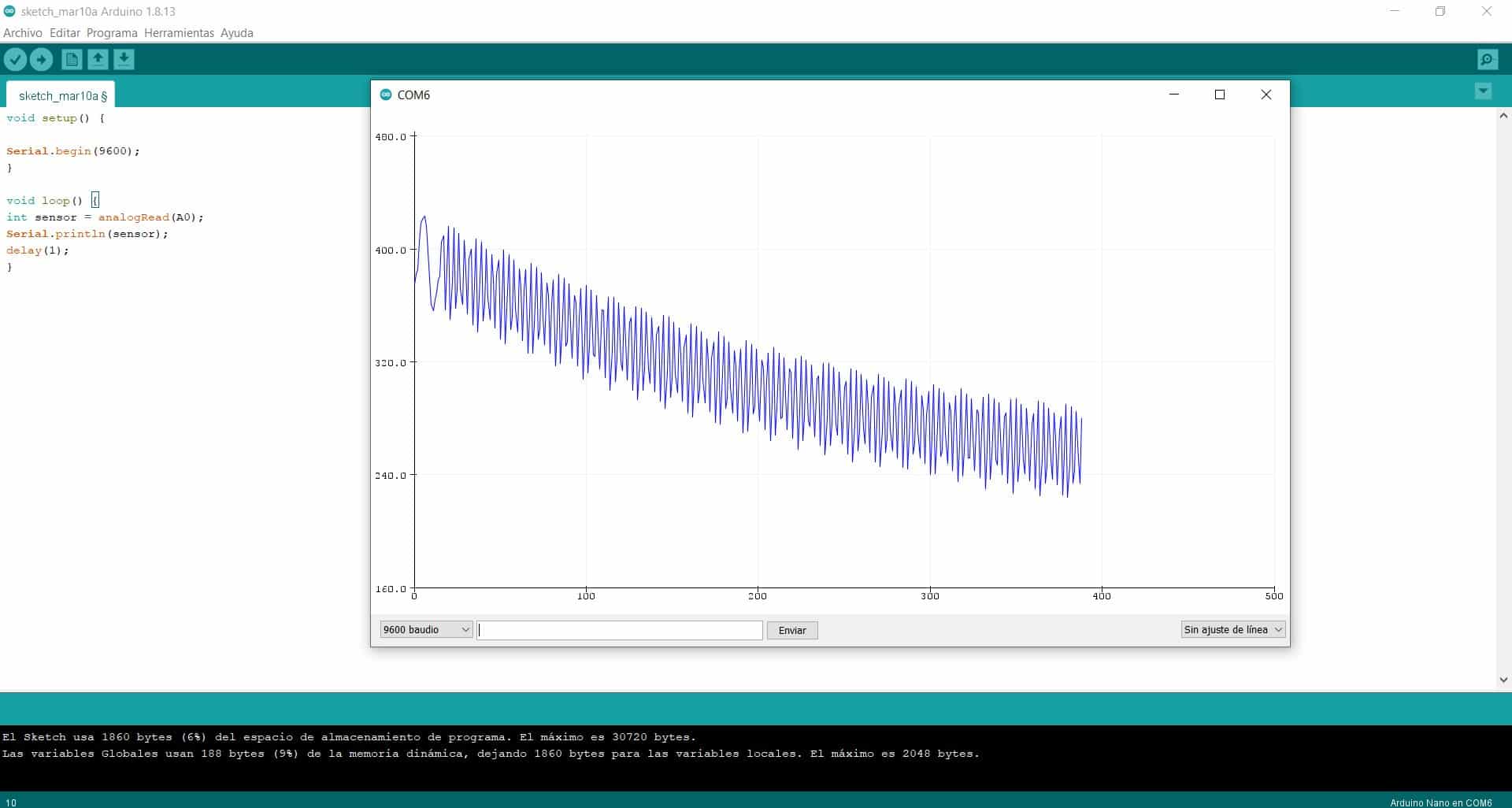
¡Et Voilà!
Finally as we already have our program ready to respond I place two jumpers, together the negative with the GND of the arduino and the positive with the A0, this to respond our graph, then you can see how the figures change on our screen, it was very interesting to know this whole process and above all make it real. 💪🥰
Second Assignment
Individual Assignment
As an individual assignment we are asked: redraw an echo hello-world board, add (at least) a button and LED (with current-limiting resistor) check the design rules, make it, and test it, extra credit: simulate its operation.It has been a real adventure to get this assignment but finally I was able to get it, thanks to the support of the team and the constant research, everything can always be achieved. 😃
Working at Home and LAB
New design and programming
My individual experience this week has been like a roller coaster, I have had many inconveniences to solve and that has allowed me to better understand the step by step processes. Thanks to the team I work with I was able to better understand the additional concepts I needed to know this week and with that information I put my knowledge to the test. 👏
A great recommendation for future students is to get the machines and components well in advance, it is complicated when you have to take a lot of time to get them and there is little time left for your designs and cabinet work. Out of everything that has happened I am happy to have learned a lot more this week about electronics and programming a board. I am excited about everything I am doing!
Design in progress
First attempt
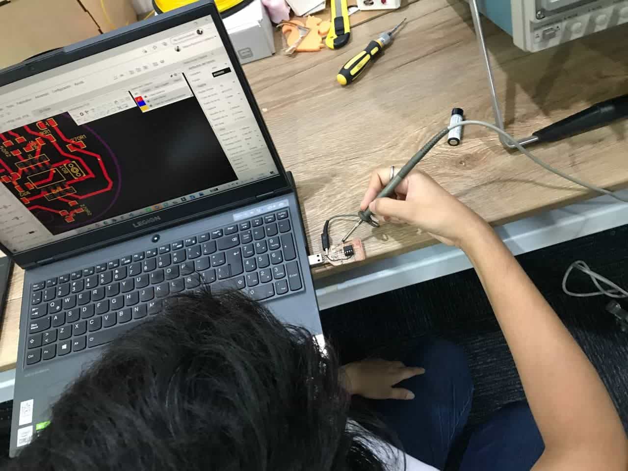
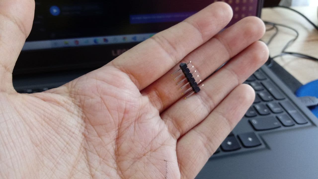
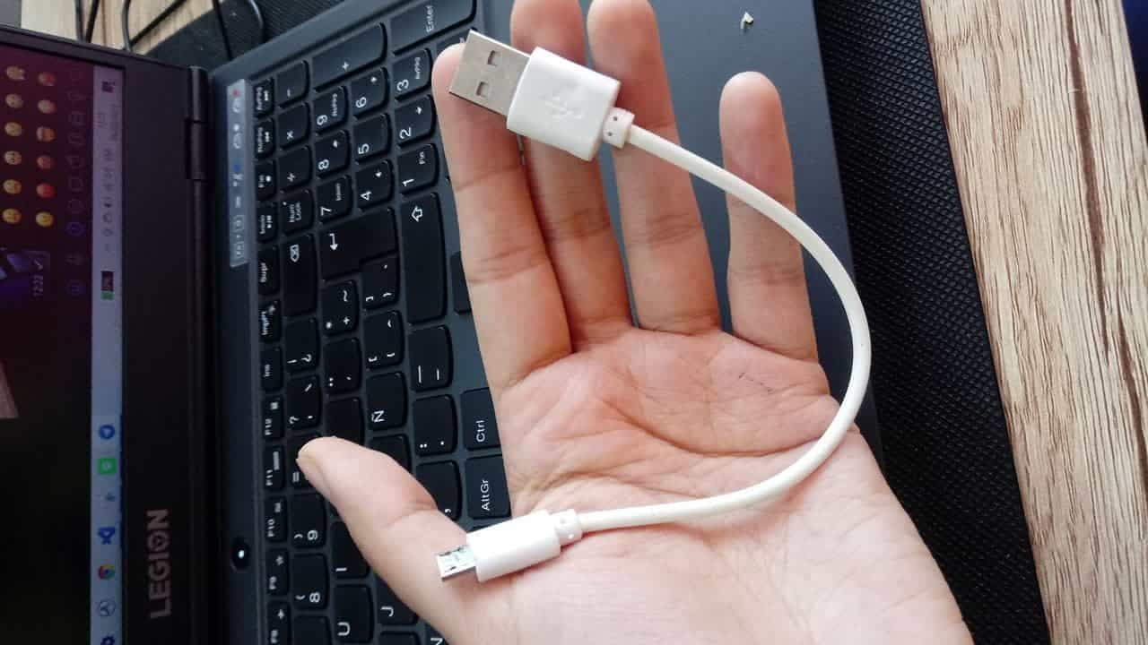
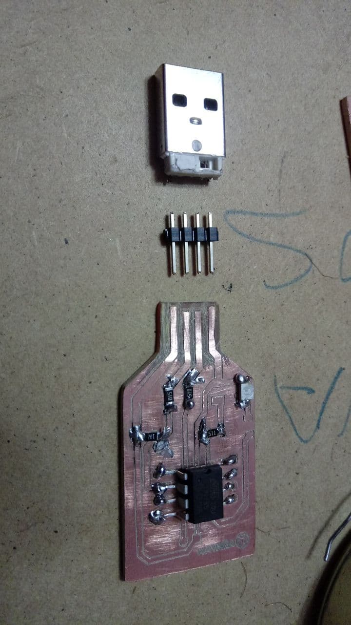
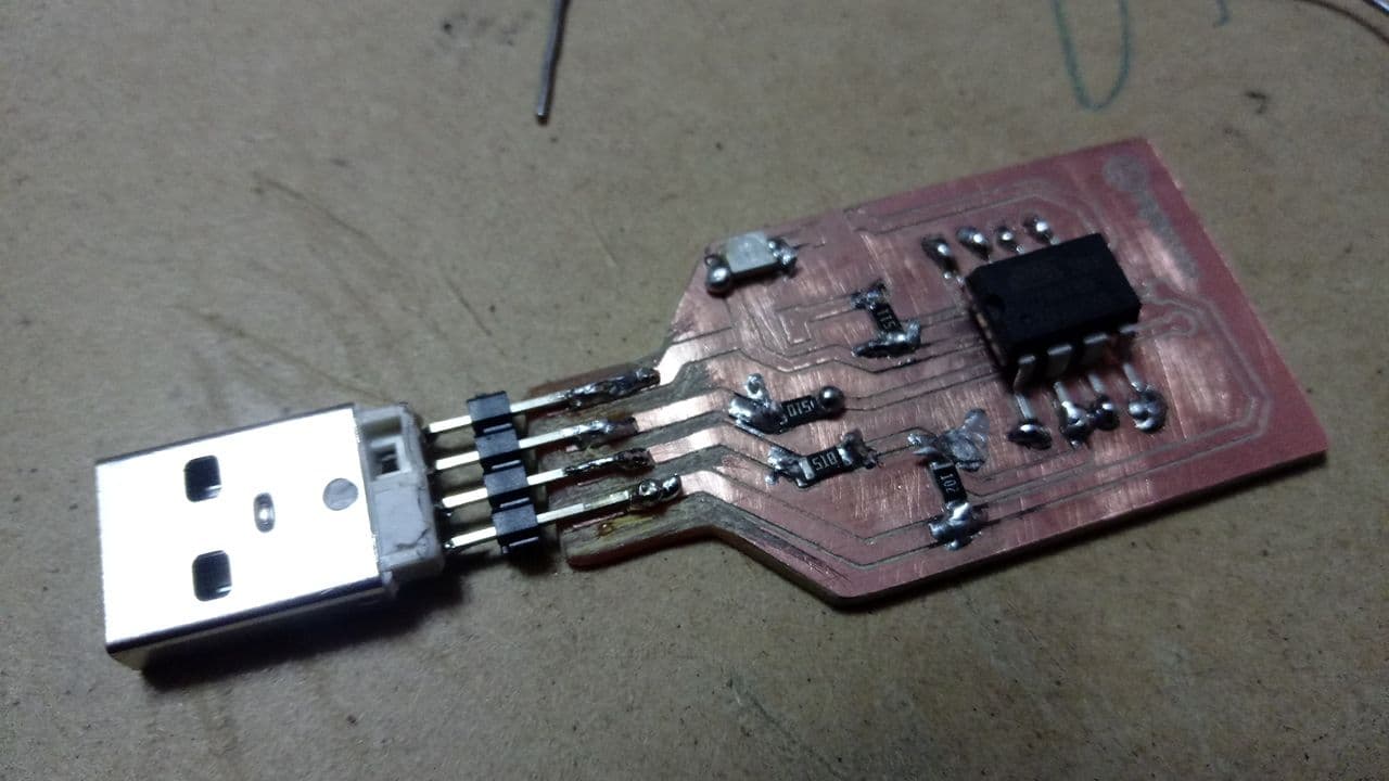
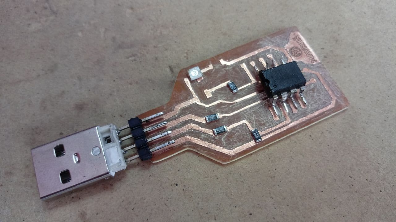
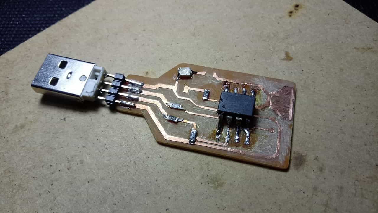
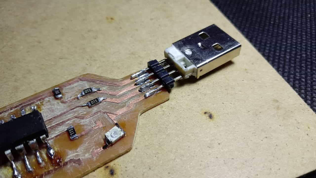
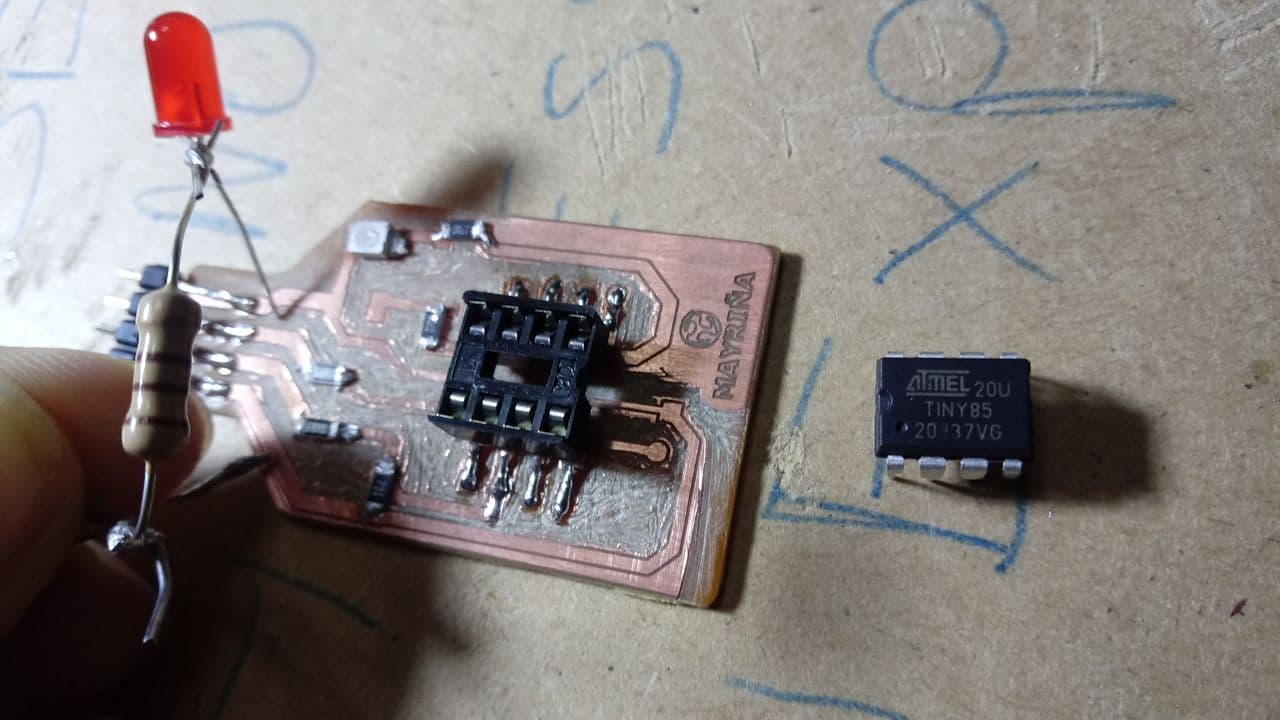
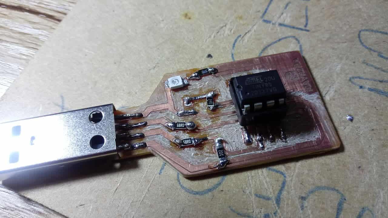
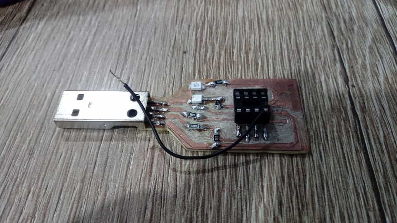
In my case, since I already had my first board soldered, I used it to test the programming. The first thing is to get the USB input to solder it together with the pins and connect them, here I show the images of this process. 🙂
Pins
USB
Order
Welded
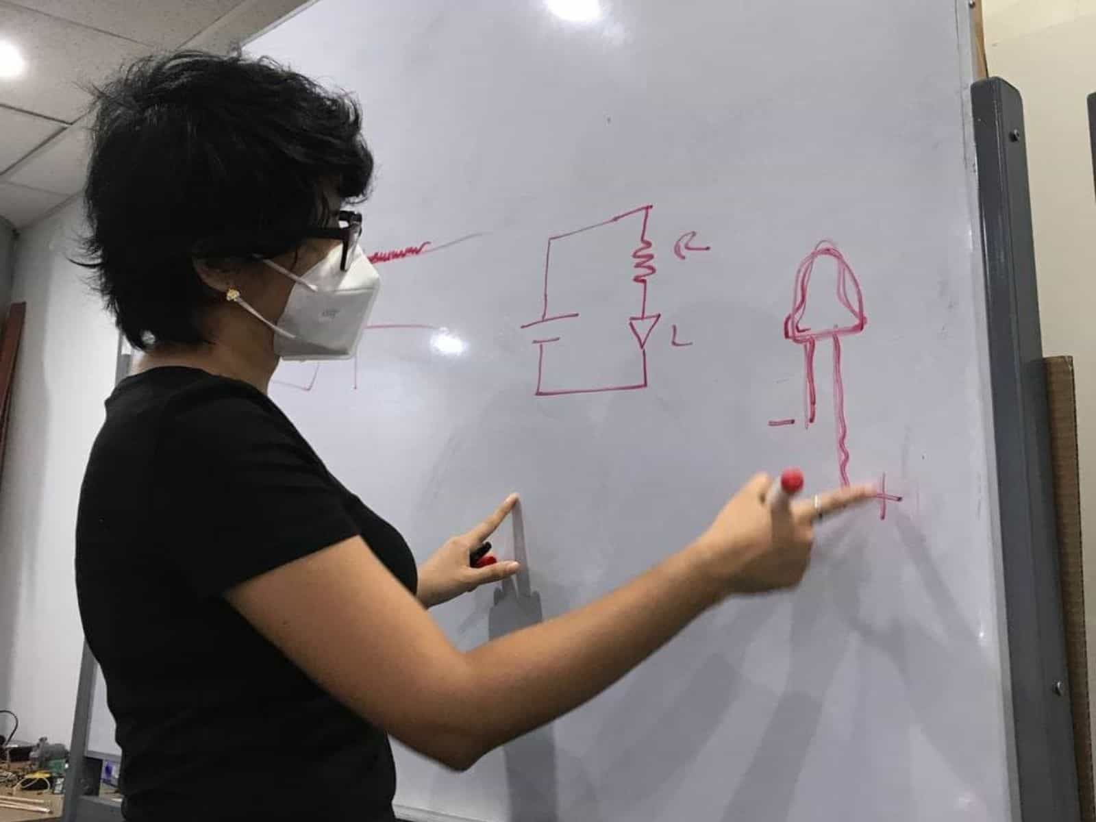
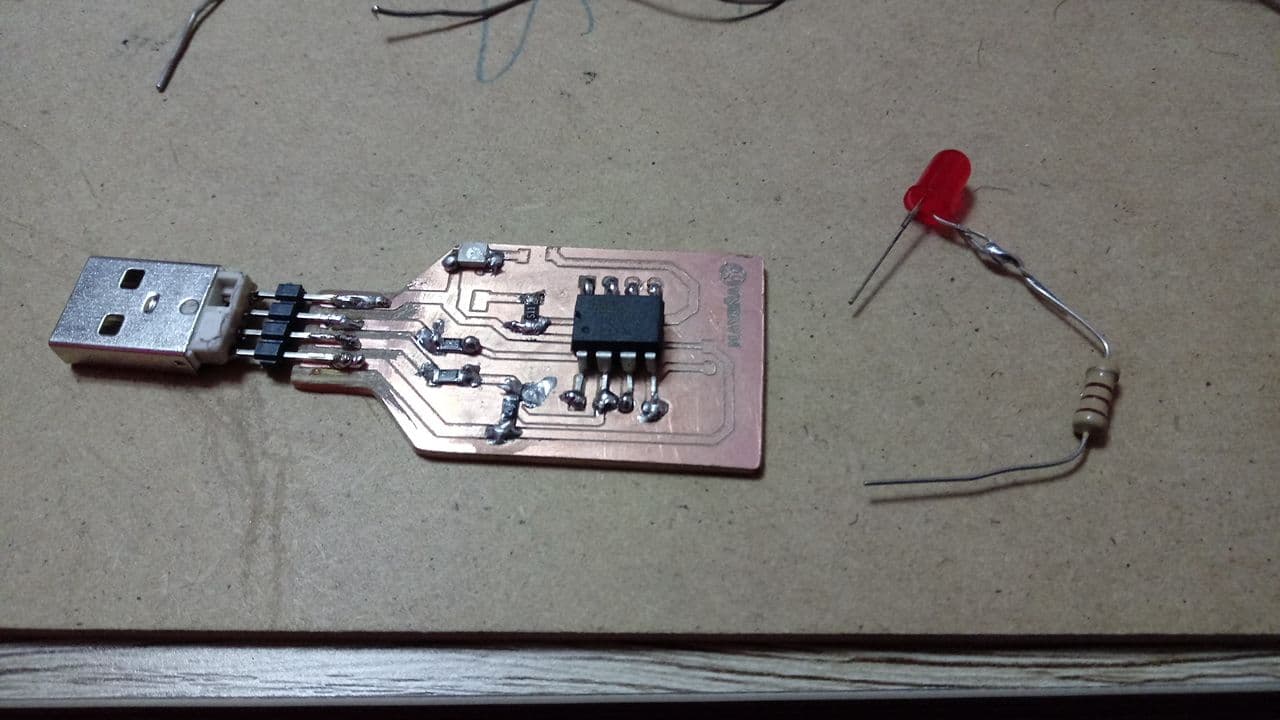
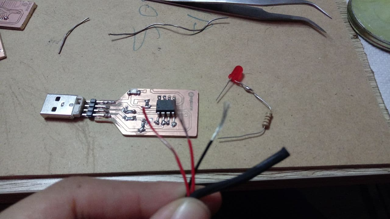
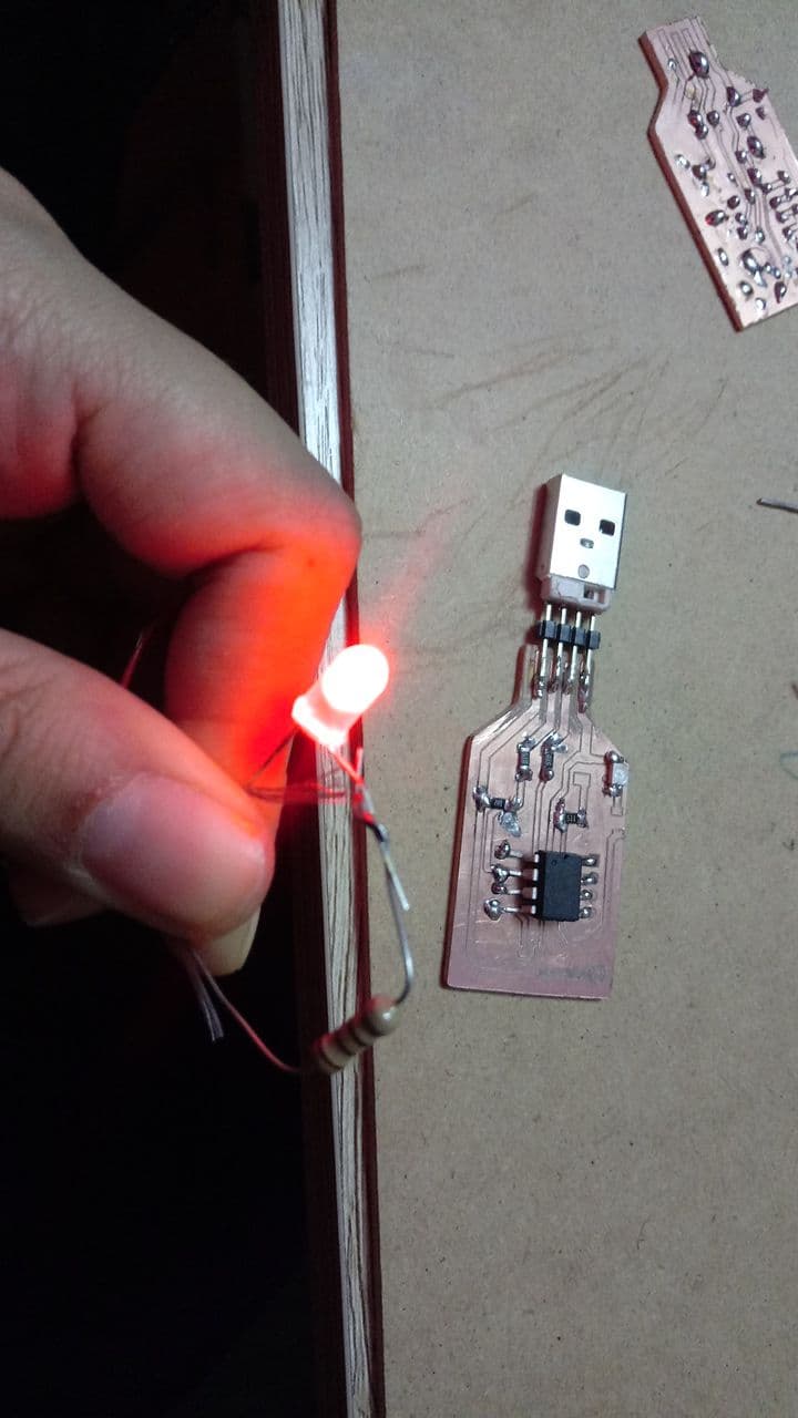
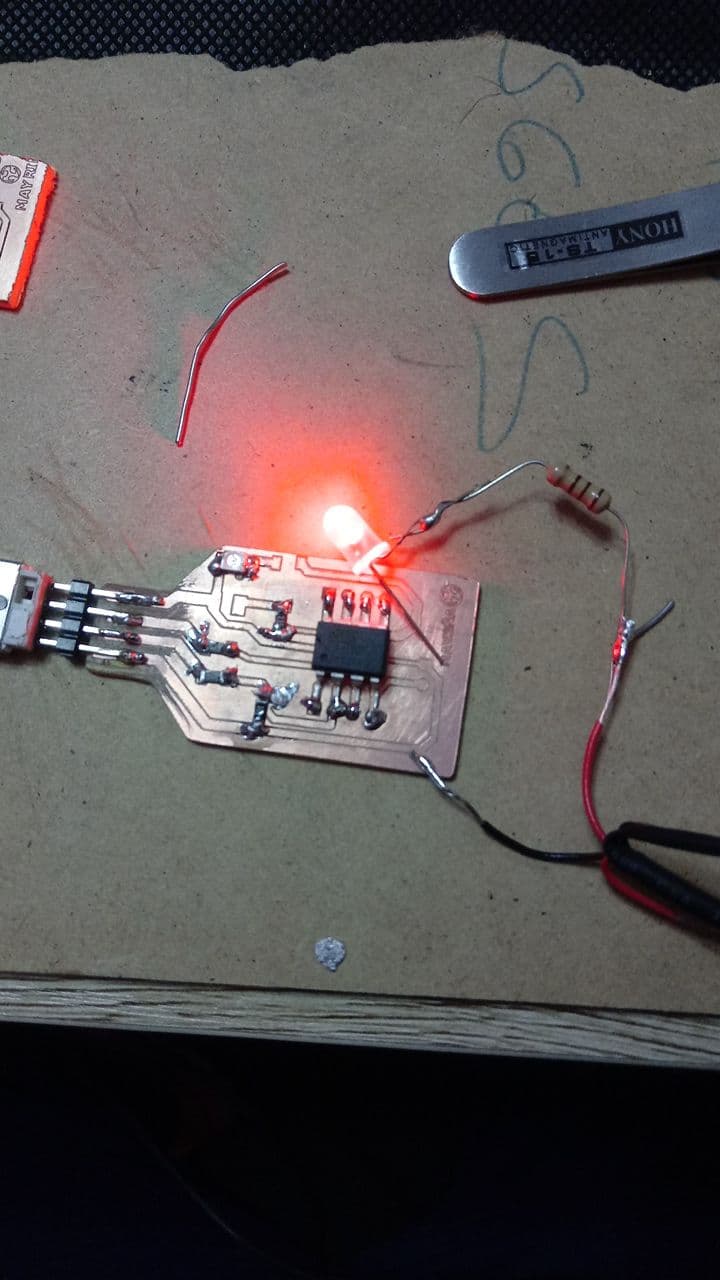
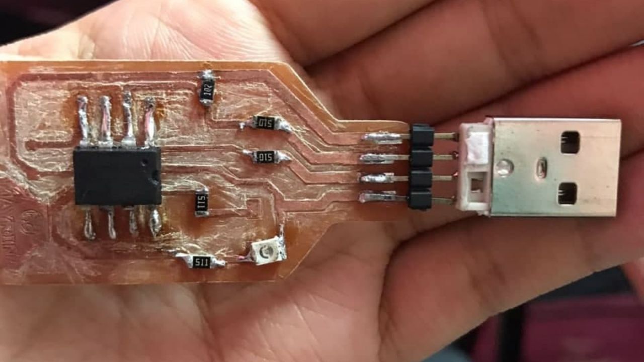
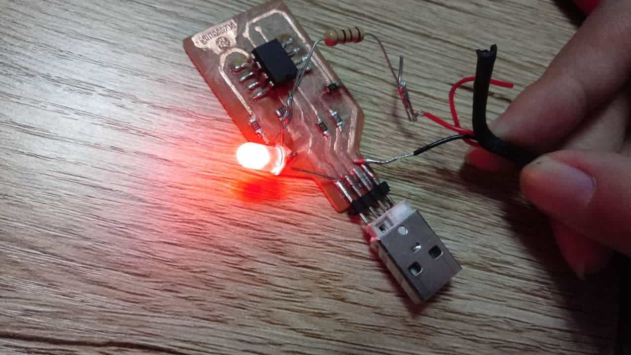
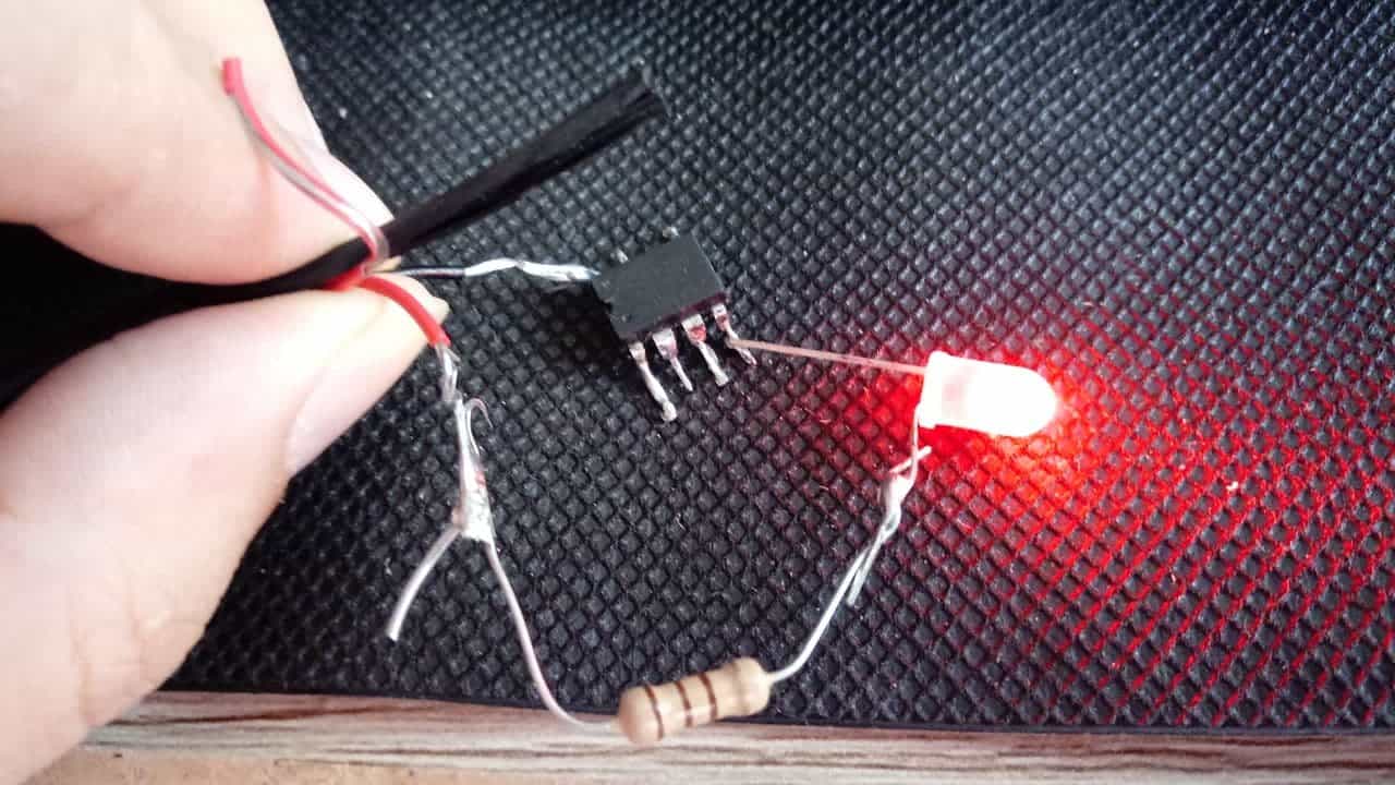
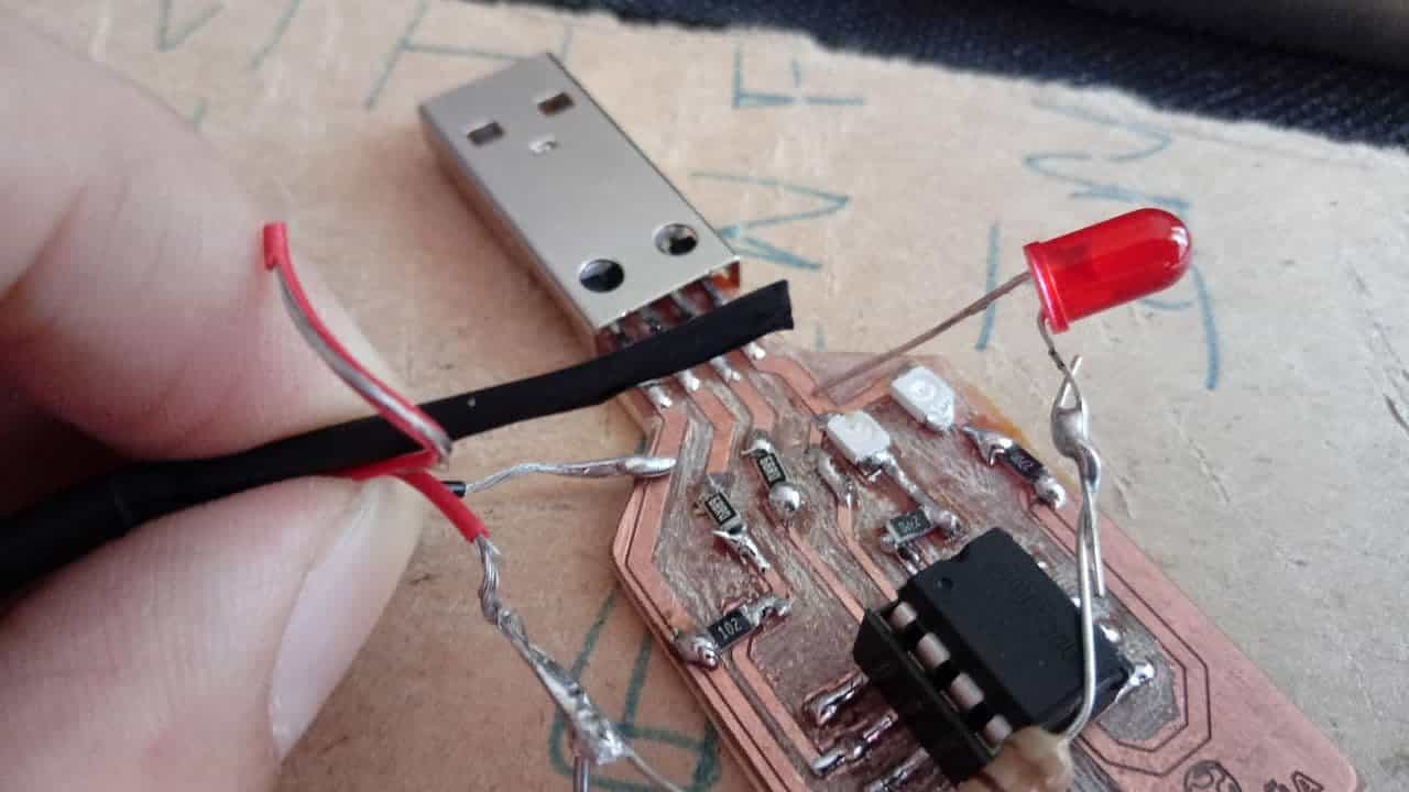
As a next step I needed to test that there was no short, otherwise it could be detrimental to my laptop usb port. For this I had to create a kind of tester, I don't have a multimeter at home so I made one myself. To build a tester you only need a led, a resistor, two wires (negative and positive) and a source, in my case I recycled an old cell phone charger and soldered it. This allowed me to foresee any inconvenience in my board, below I show what happened.
PCB/LED/Resistance
Cables and sources
Test
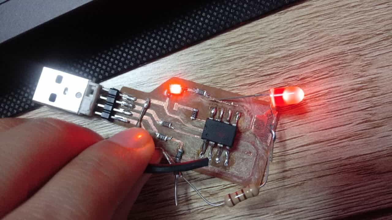
Short circuit
Second attempt
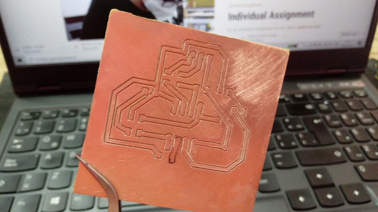
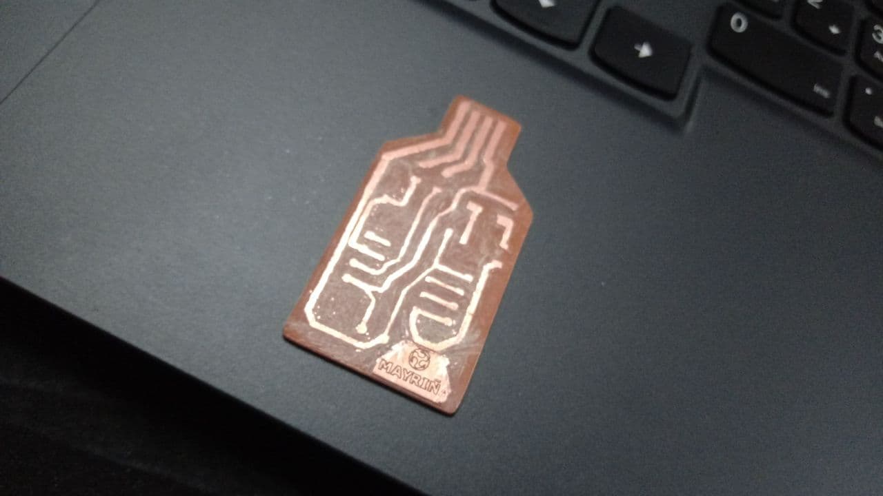
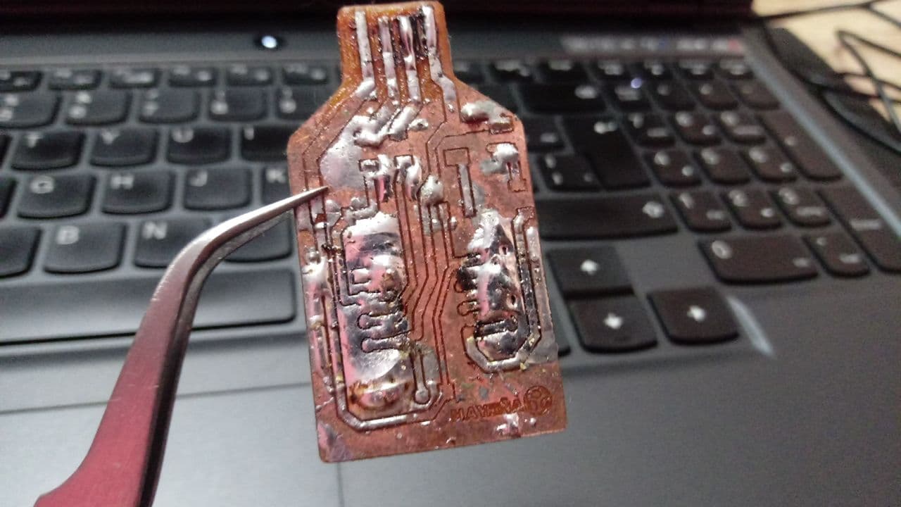
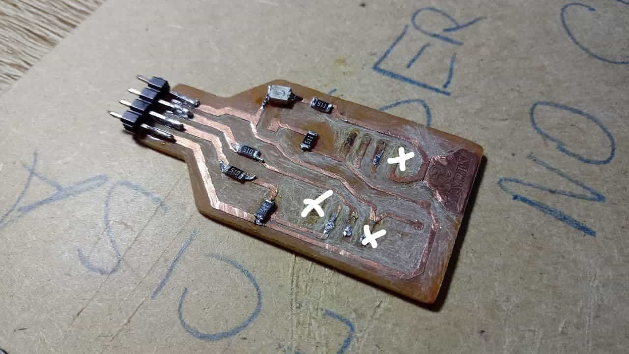
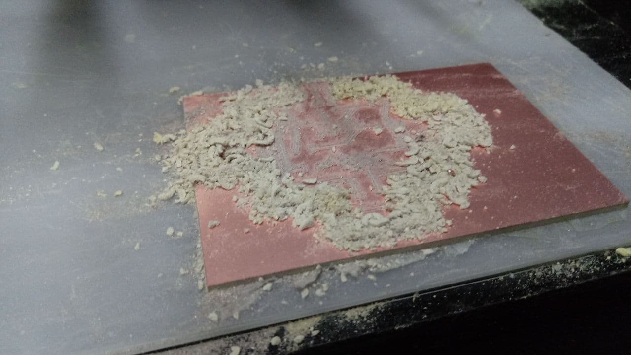
The result was not good, 😢 my board was shorting out, this needed to be repaired before any further steps. At first glance my soldering was not good and since my board was not completely clear of copper it made it more difficult. One recommendation is not to have the board like mine because at the moment of soldering you need too much precision, for us beginners it is not a good idea so as I didn't have the machine at home I had to do a copper clearance by hand on my second board.
Copper-free plate 2
Copper-free plate 2
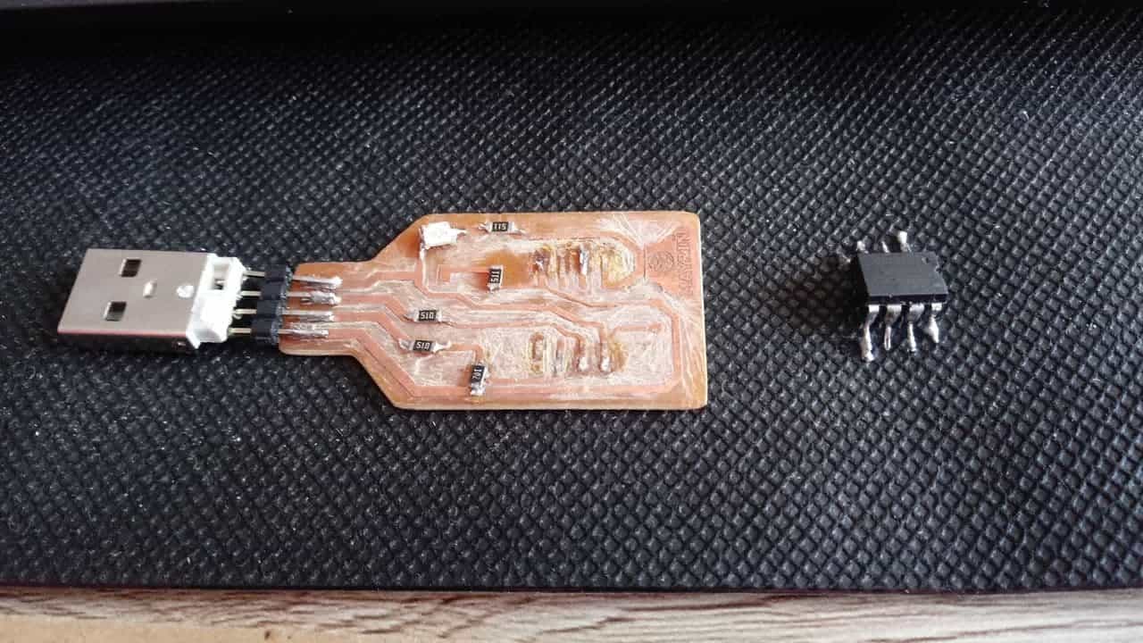
ATtiny unsoldered
Removal of all components from board 1
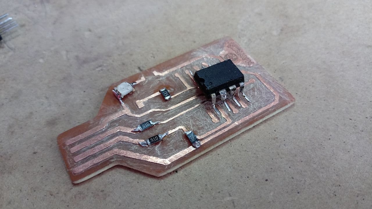
Location of components on the second board
Location of components on the second board
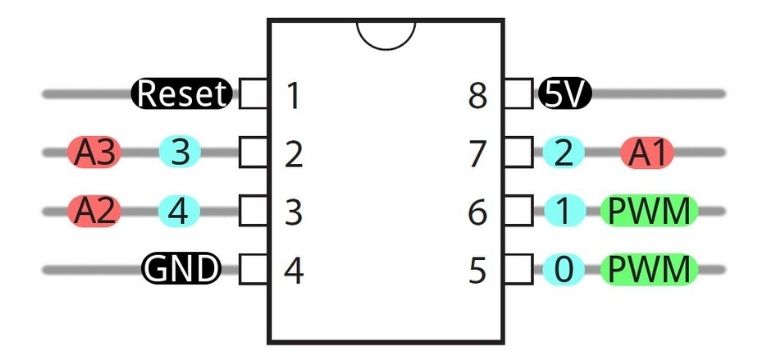
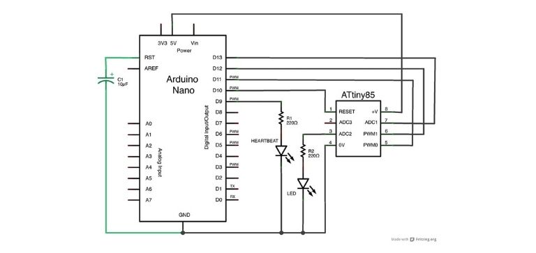
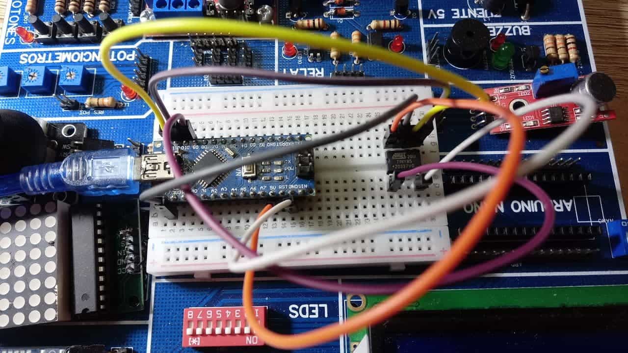
Before soldering the ATtiny 85 I did the programming on my computer, this will be useful for when I connect my board with the USB input and I can recognize it. To do this I used FABINO, an arduino trainer that contains different components that helps me to make simulations and I used it in week 4 to start learning about electronics. Next I will show the steps for programming the ATtiny 85. ✔️
Attiny pins
Connecting the attiny with arduino nano
Position of the ATtiny on the breadboard
My attiny on fabino's protoboard
To get the programming I needed to download the ARDUINO 🙂 program from its official website (here) and download some folders to install the drivers (here). With this I followed a series of steps that I will explain below.
Official website
Program
First step
Uploaded
Choose the port
Uploaded
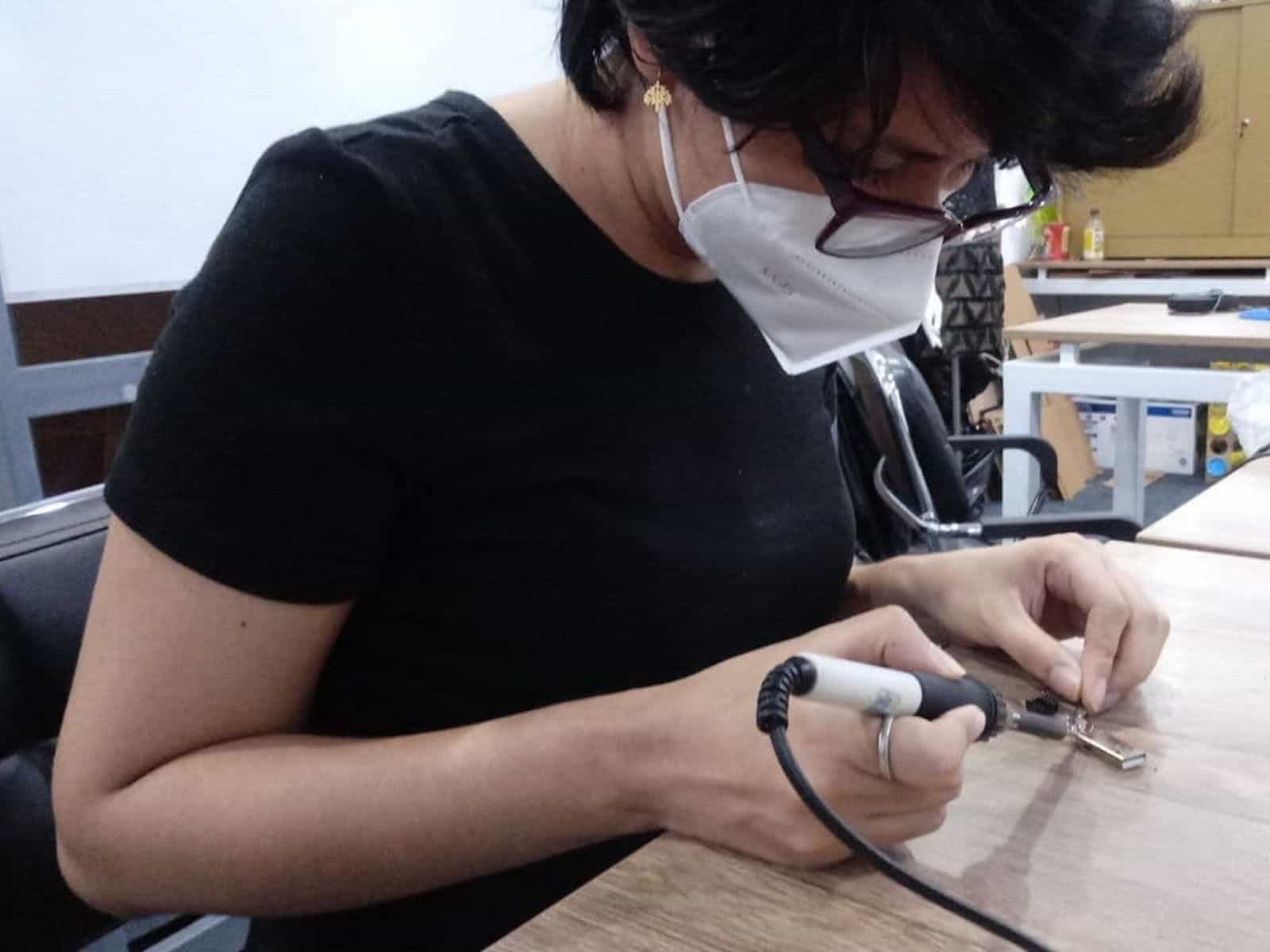
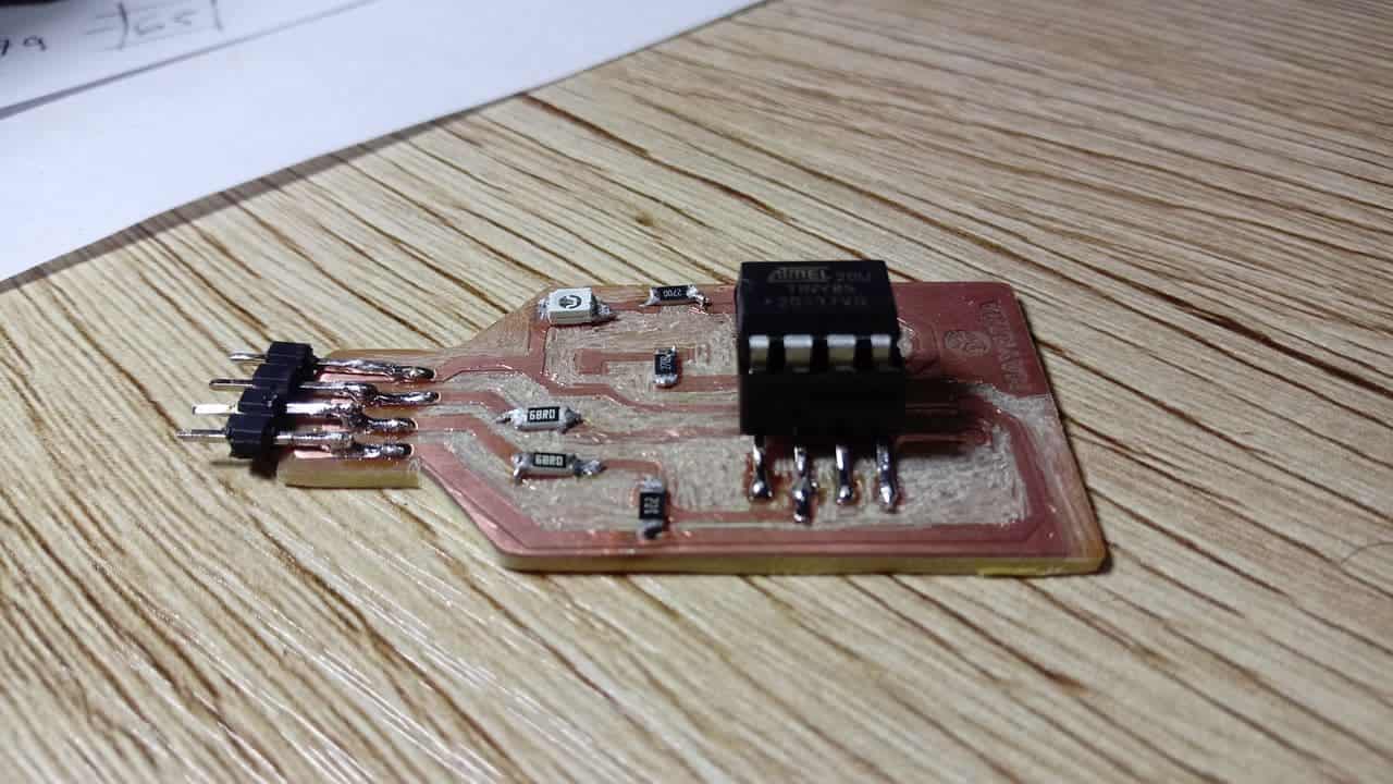
After getting the programming of ATtiny85 I had to solder it to my board, I was very careful with this soldering because the first time I did it I made a mistake in the orientation, I recommend to be very concentrated because otherwise there may be some details that not being fulfilled will spoil your whole process. 👌
ATtiny welded
USB welded
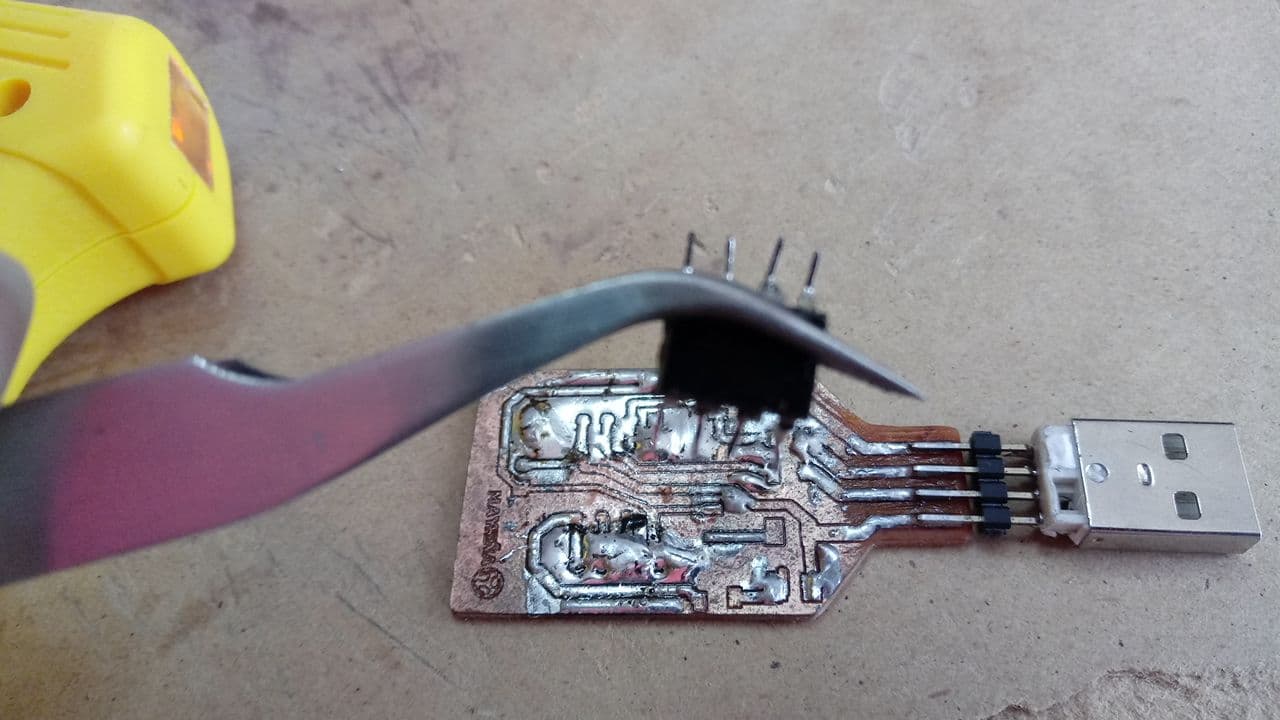
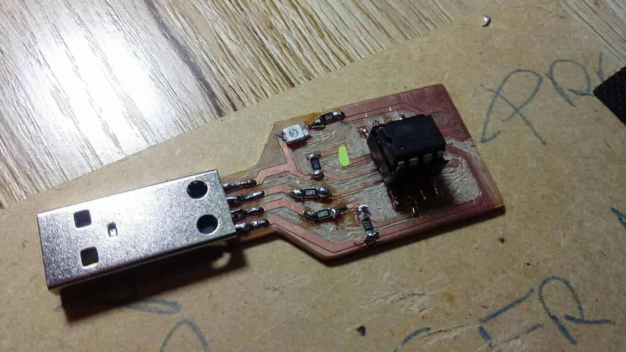
The last step before connecting it to my computer is to do the current test, when this happened I realized that my board was short, I checked all possible connections and scraped them with my blade but it was still short. As a conclusion, after a long time, the problem was being my ATtiny, I tested it and it was burned. 😢 Here are the pictures.
Welded plate
LED
Short
Short
Third attempt
On my third attempt I had to get another ATtiny for my plate, thanks to my partner Hayashi Mateo we were able to get the next day and continue with the next attempt. For this I had to remove once again the ATtiny and as I had put the soldering iron on it for a long time to change it, the copper started to come out. It was for this reason that I made use of my third plate, here I show some pictures.
Copper-free
Copper-free
Third plate
Too much copper
Copper removal
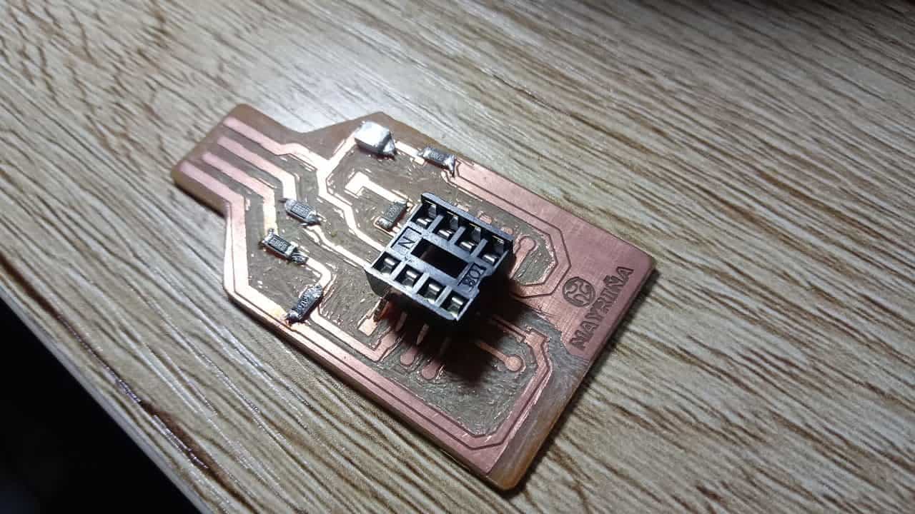
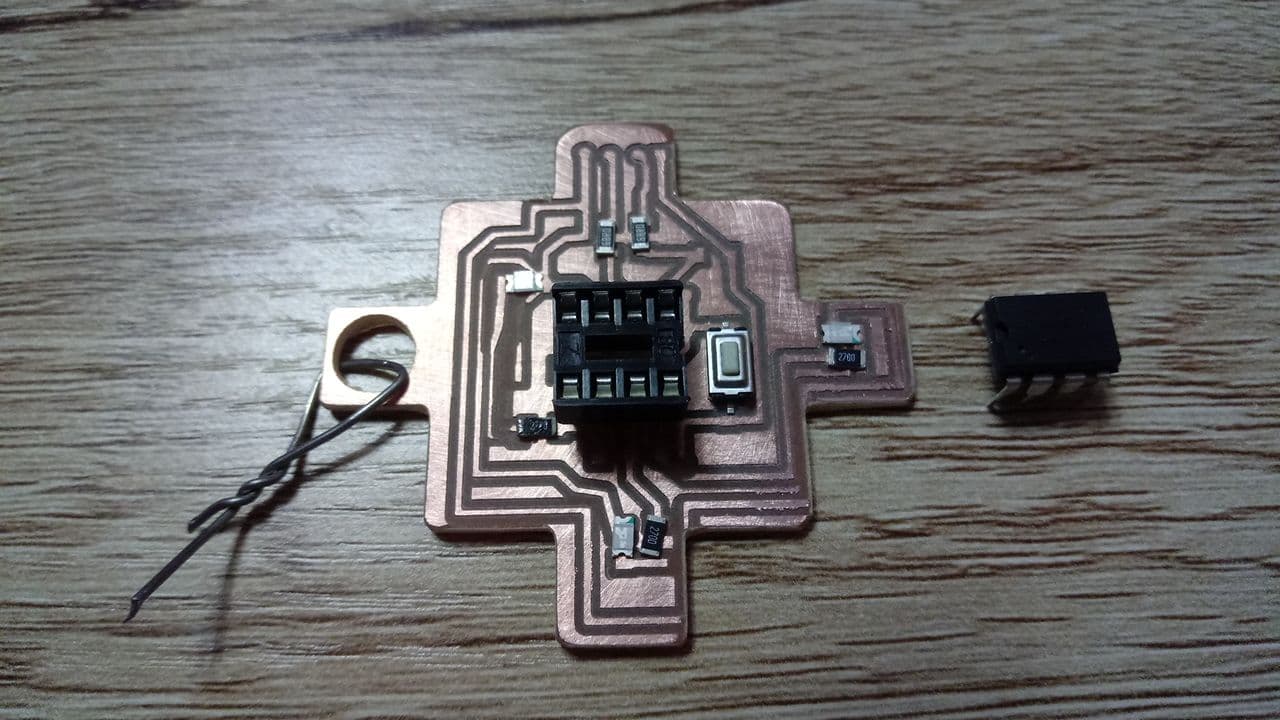
Zocalo - New component
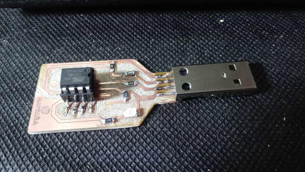
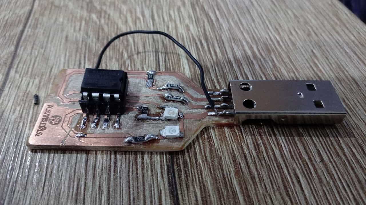
After that I did the current test, all my components were correctly soldered (thanks to practice) and in particular it helped me a lot to use a socket because I think this protects a little more the ATtiny, for beginners like me I recommend to use it, just bend the legs at the base to solder it without problems. 💪
New welded components
ATtiny85 ready
Plate ready
Login to my computer
Apparently everything was going well, but my badge was not being recognized. This time I managed to see my LED light up and my computer beeped when I inserted the USB but it was telling me that the device was not recognized. What was going on? 😢
Copper-free
Copper-free
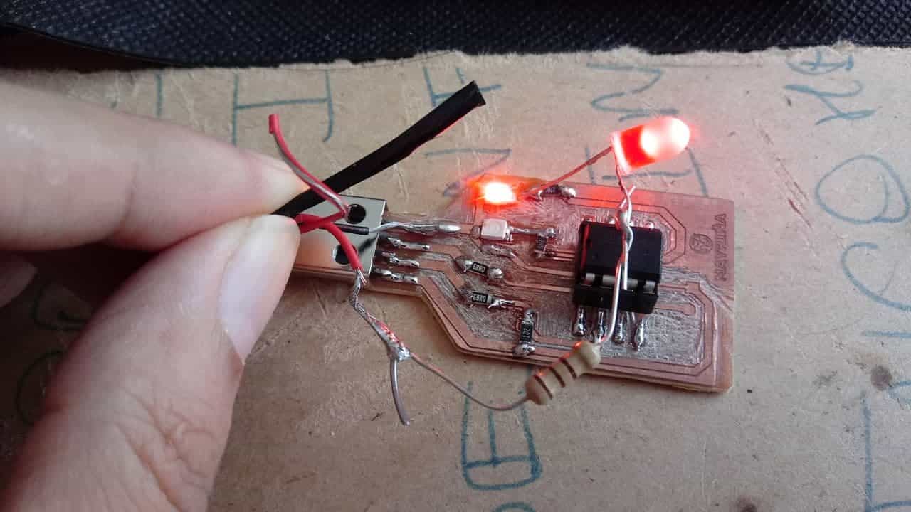
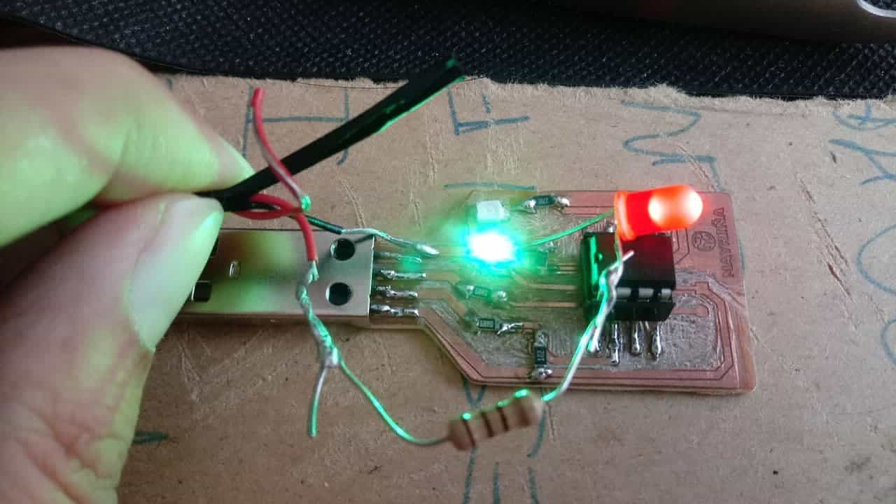
My first mistake was to solder this led resistor in another place, I had to correct it. After that I did the tests with the leds and the continuity between the traces. 🥵
Current free
Red Led ok
Green Led ok
Short on traces
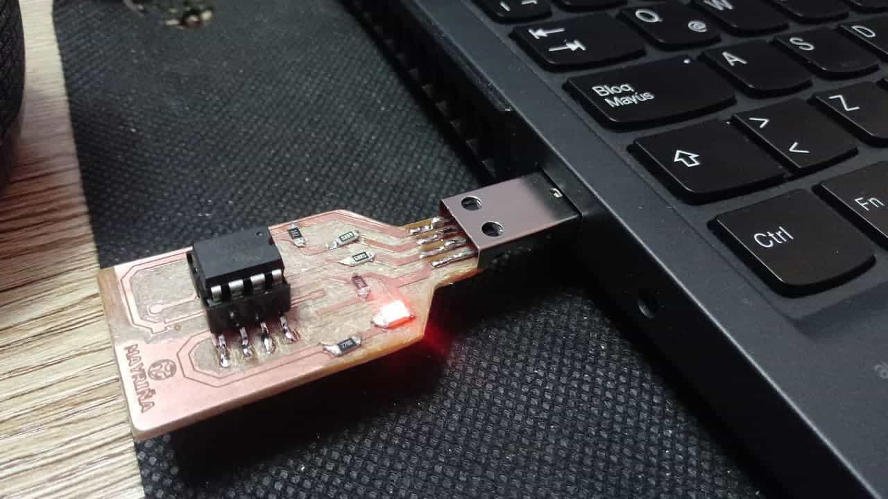
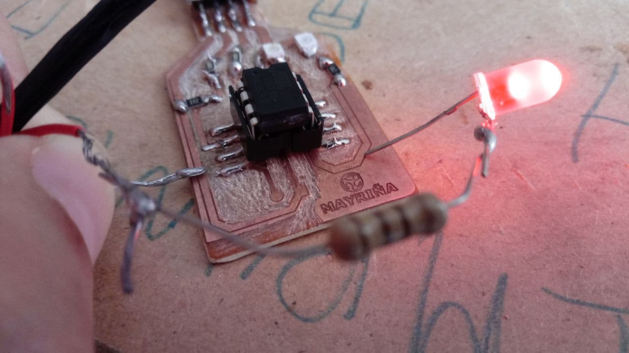
Since there was a short between paths 1 and 4 and I still couldn't make the connection I made some new ways to solve my board. This board was much better soldered and I didn't want to mess it up so I fought to the end to make it work!
Finally
In order to finish with the functionality of my board I had to do three things, as there were still traces that shorted I had to use an external cable in the connection between pin 4 and trace 4 (because the current did not arrive), cut the track 4 to connect it with a copper wire (since a small part of the trace was not working either) and change the resistance of the green led because when I connected it to my computer it did not turn on (this resistance apparently had burned). Next I show part of the process.
Cable on pin 4
Connection of the cable to the negative
Burned resistance
New resistor
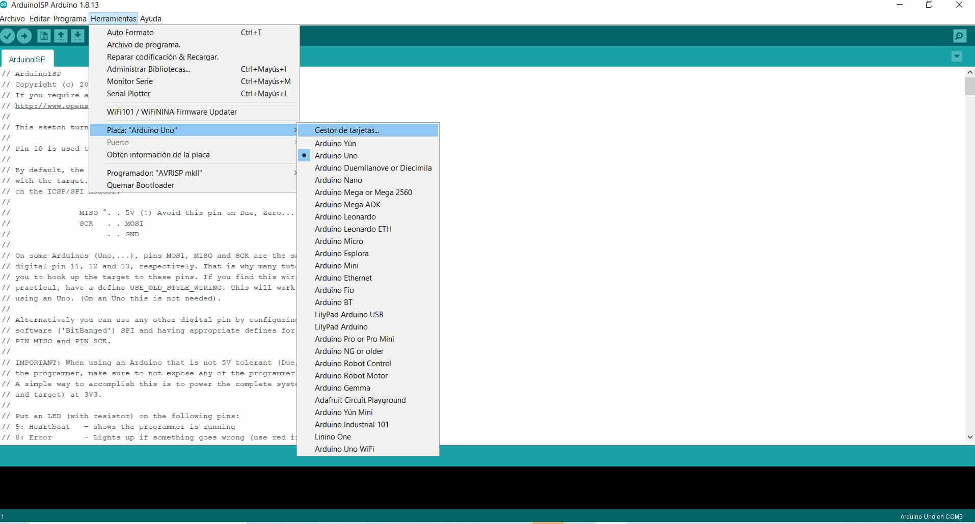
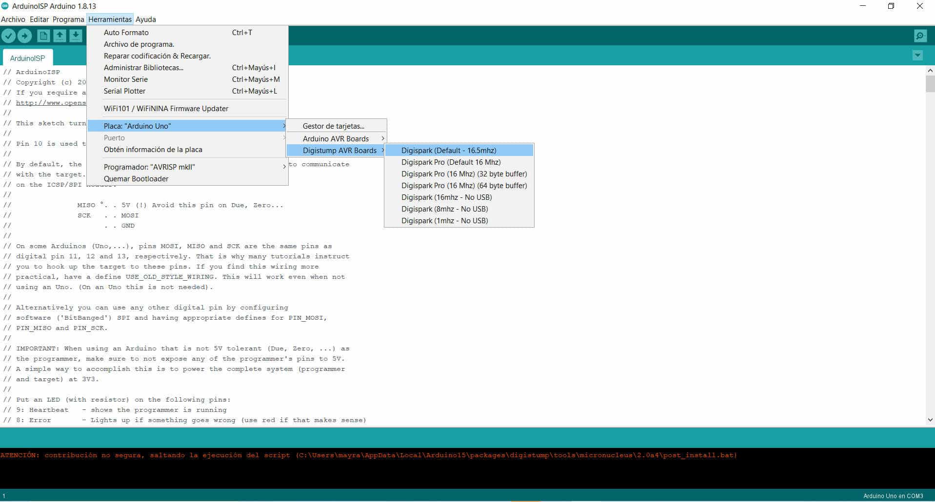
The next step was to do the programming with the arduino program, this was the acid test so I was very scared because it would be practically my last attempt. 🐵
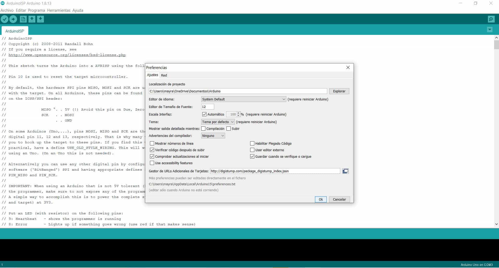
Preferences
Link
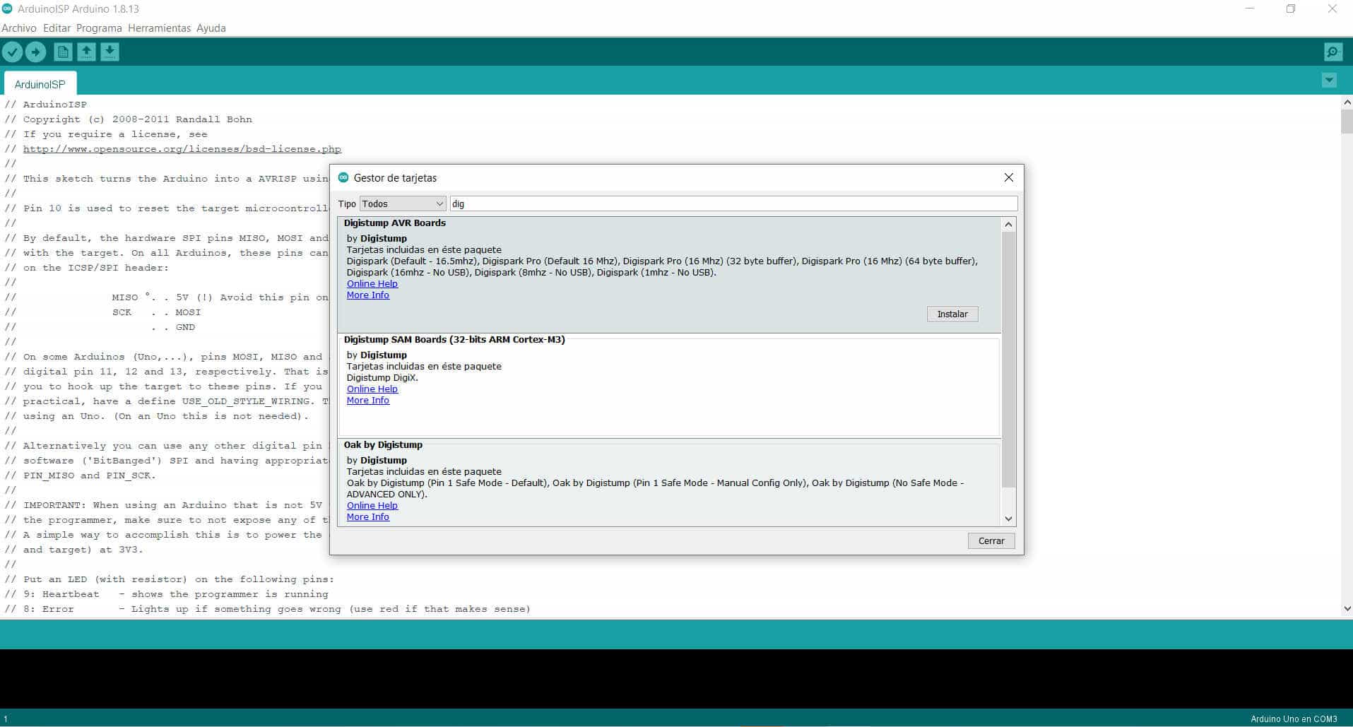
Card manager
Digistump AVR Boards
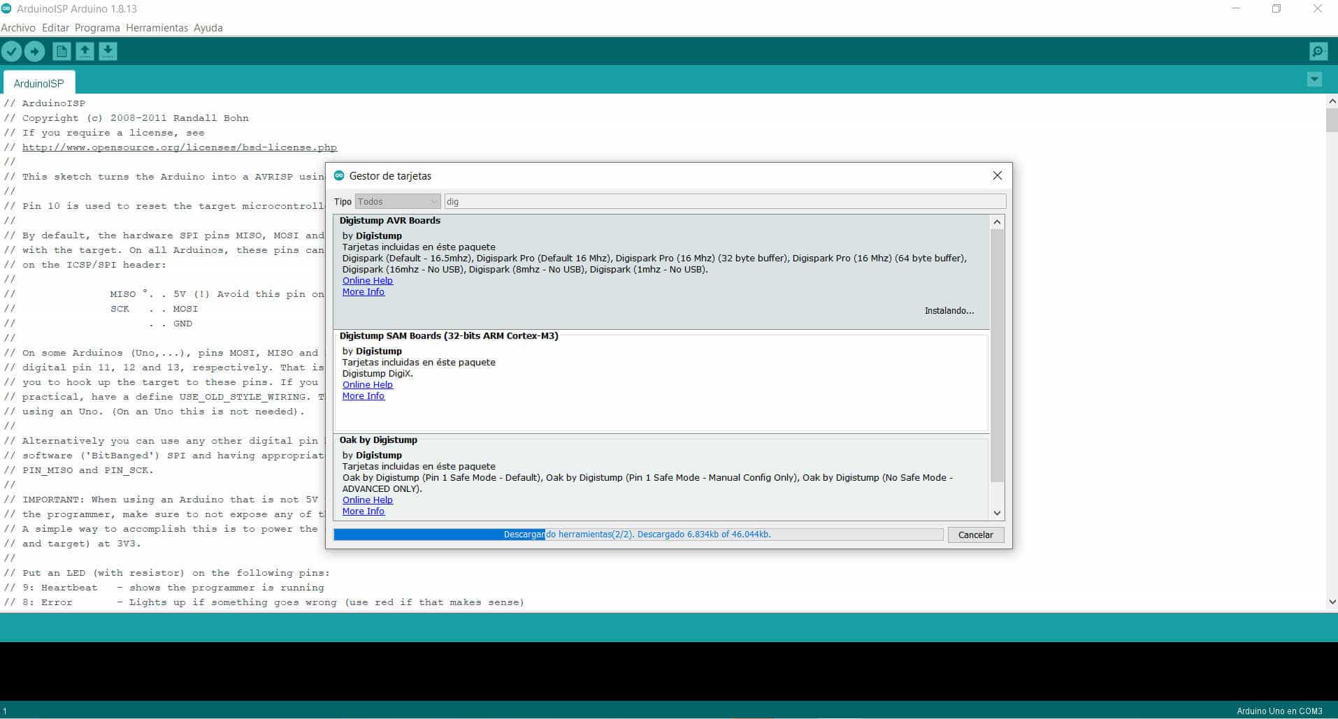
Installing
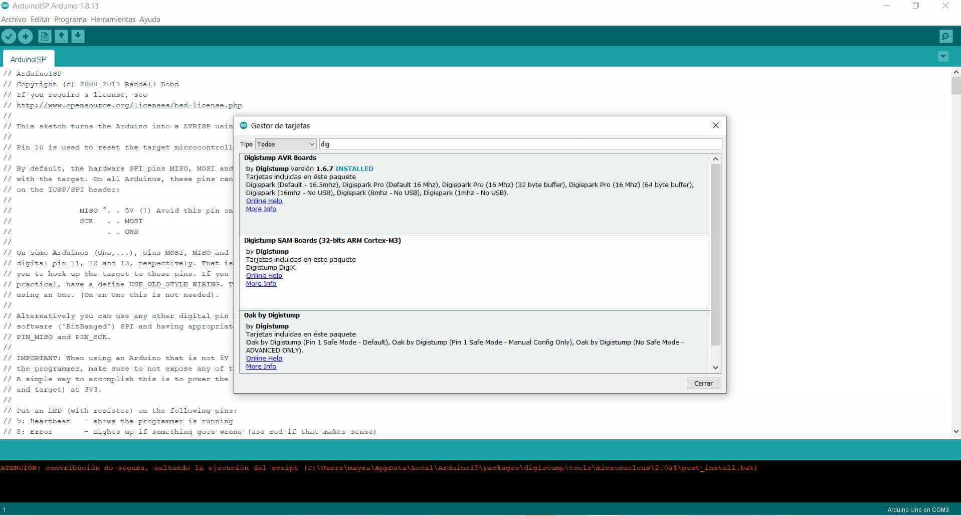
Installed
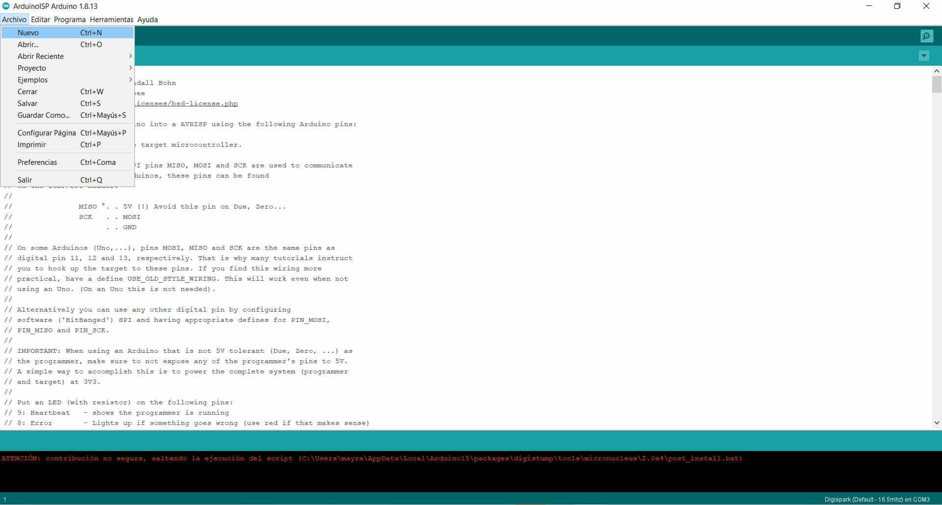
Digispark
New
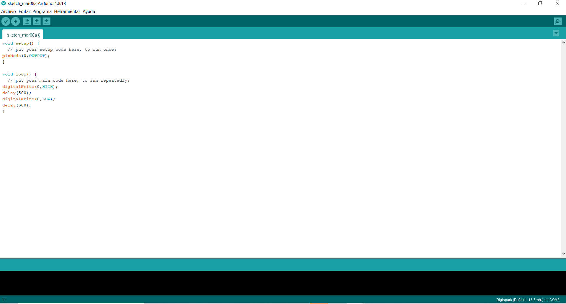
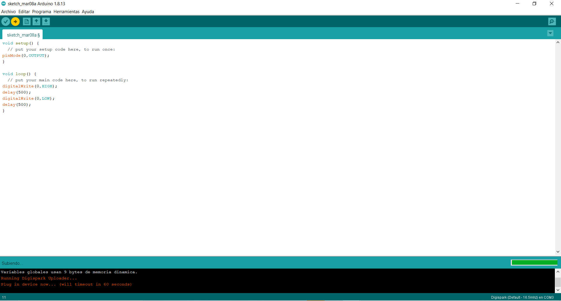
Programming
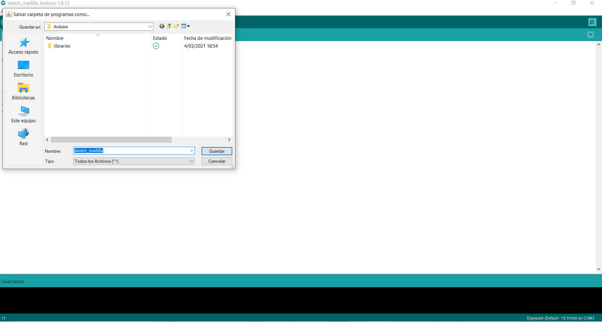
Save and cancel
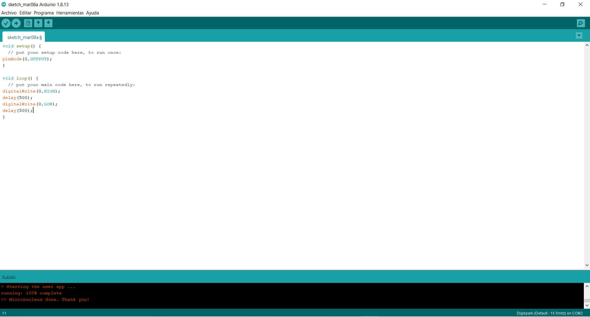
Up
Uploaded
New design
In this new opportunity I made a circuit from scratch considering now new components, now I know that it is very important to be very cautious when building the board. One of the things I will not do again is to use the thick soldering iron, that does not help at all. Here are some pictures of the design process.
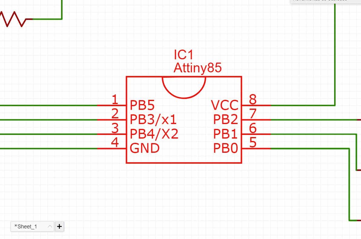
ATtiny
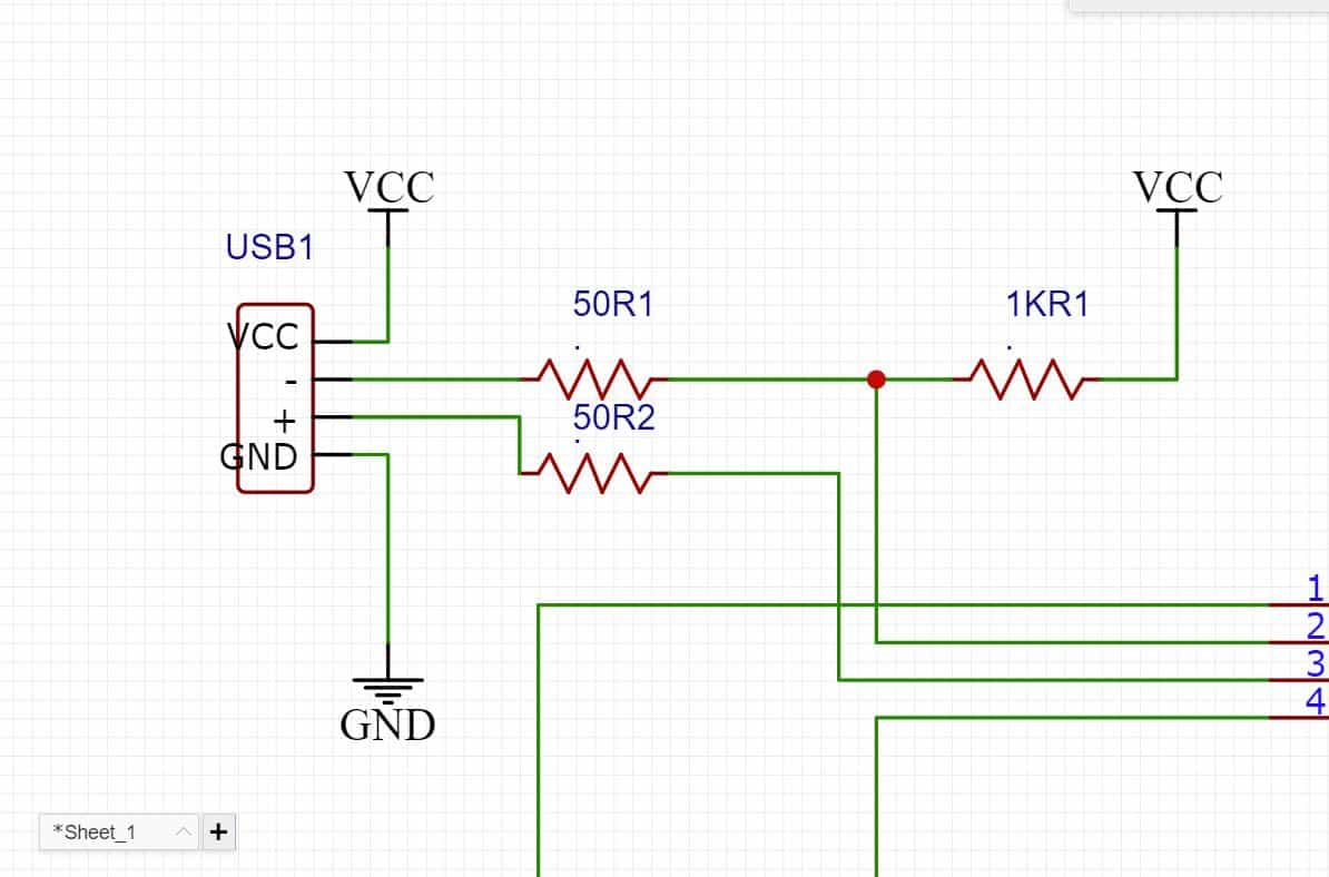
USB
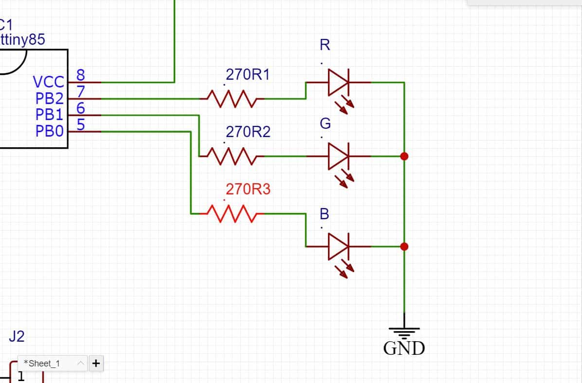
Three Leds
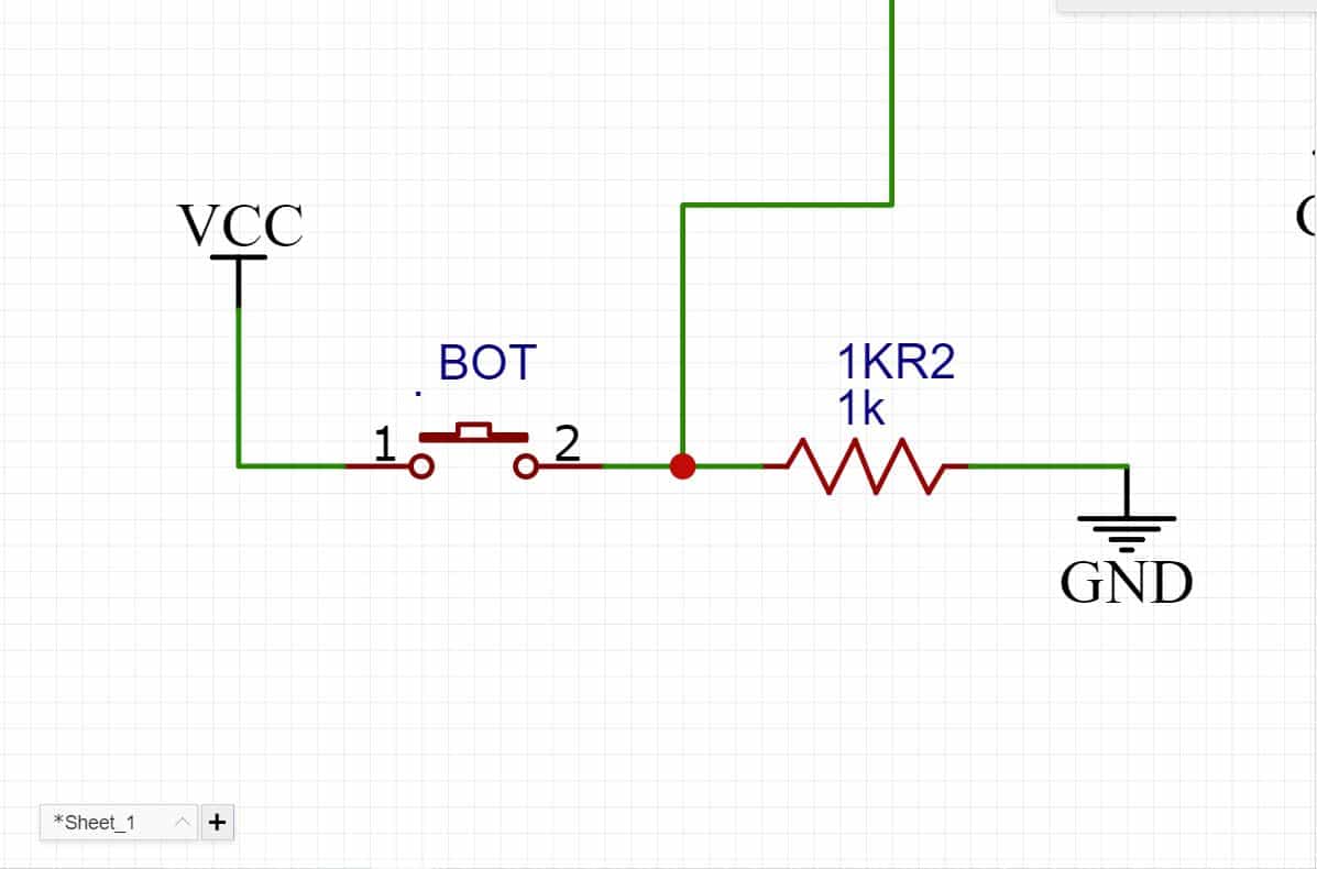
Button
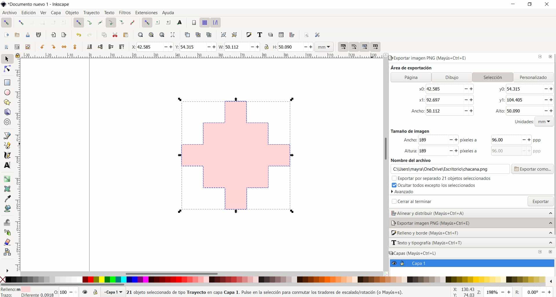
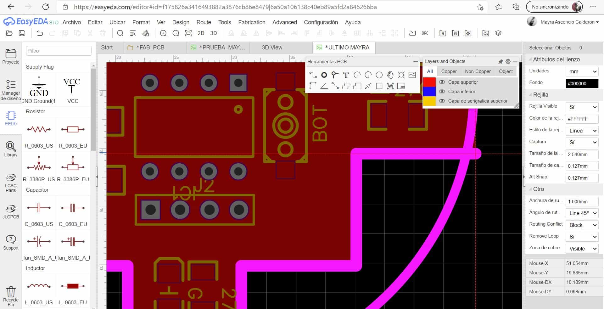
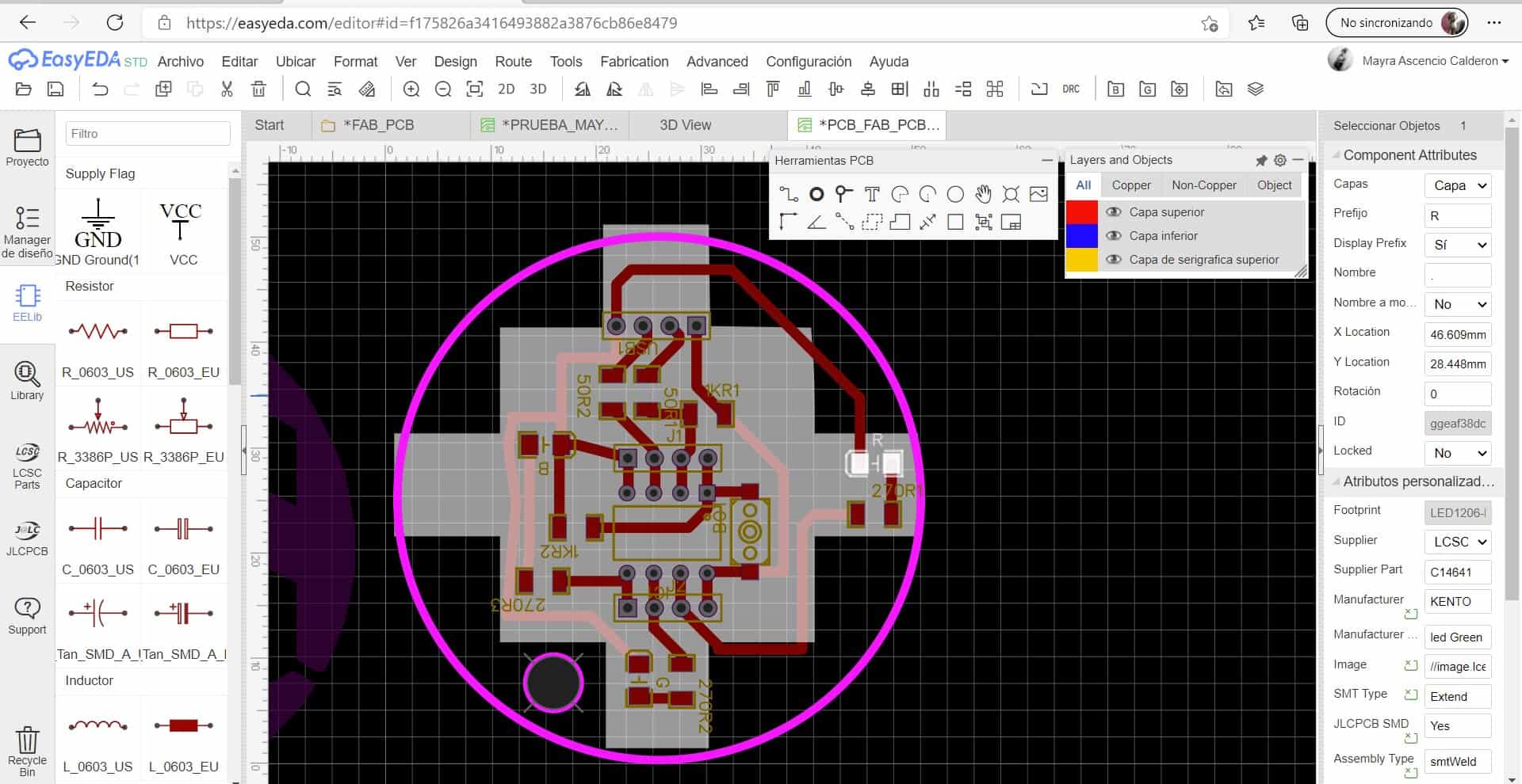
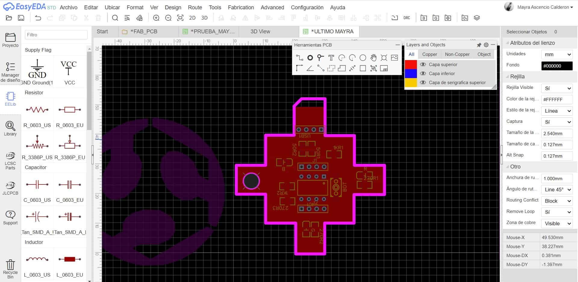
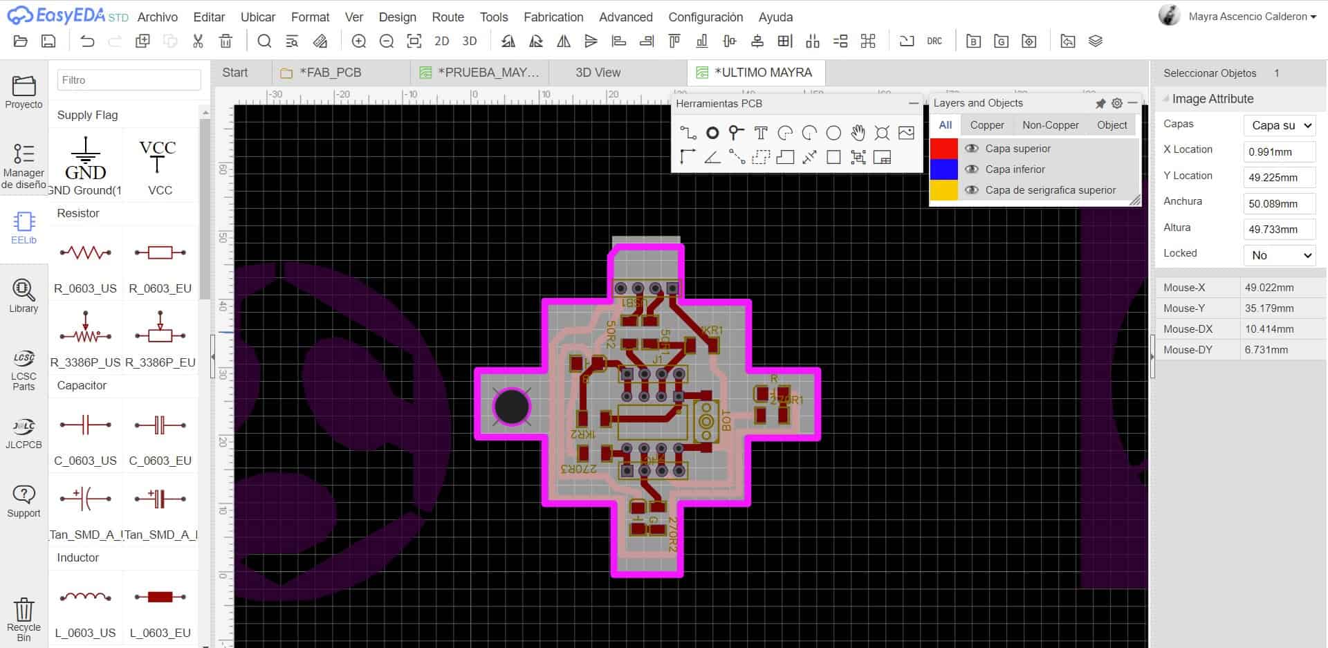
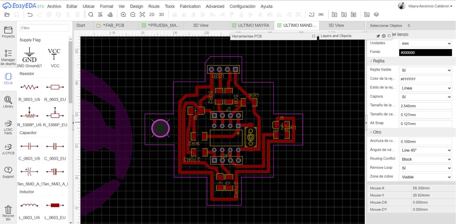
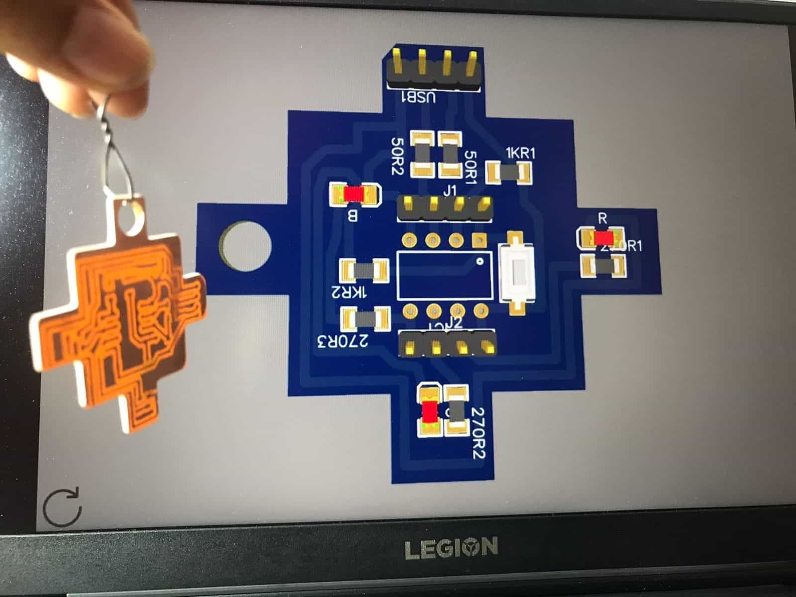
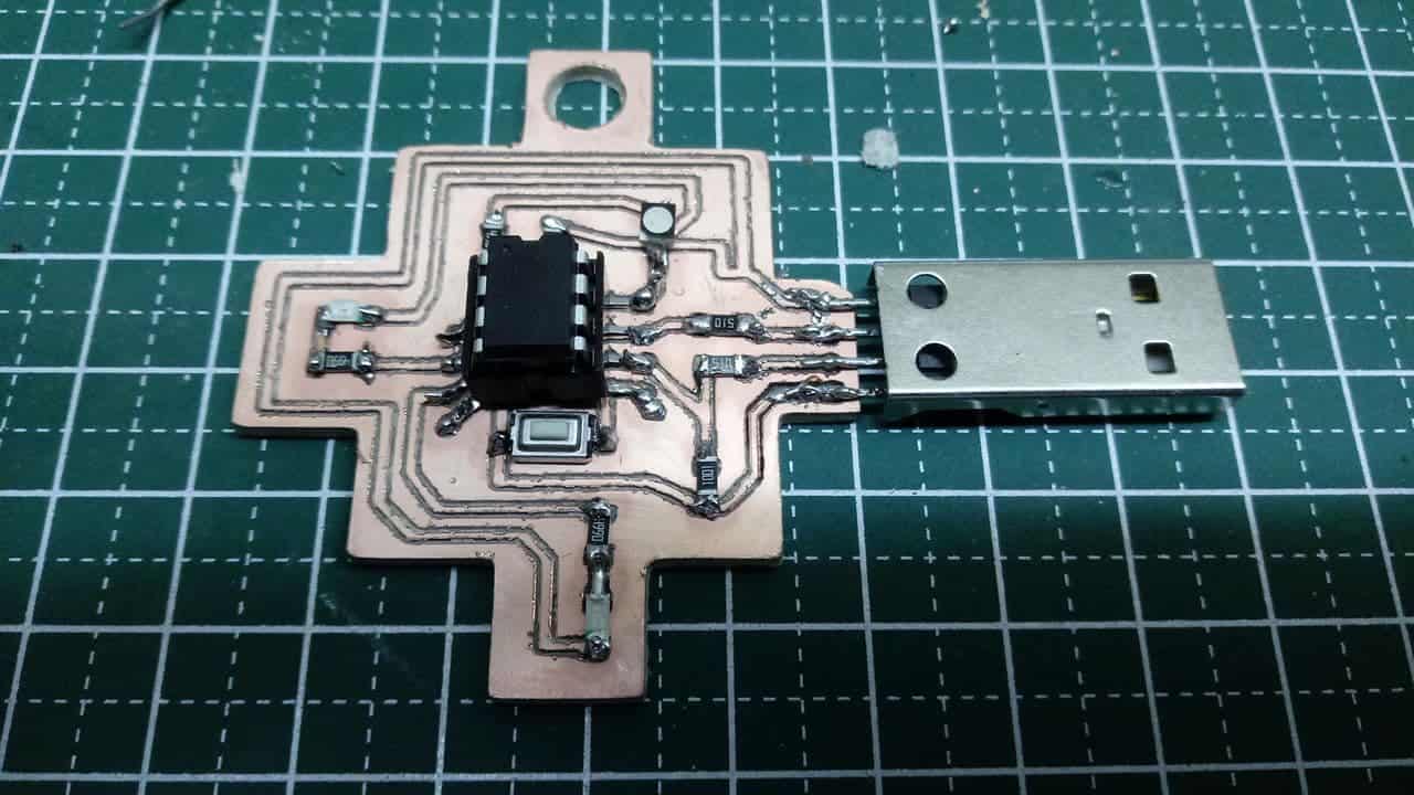
After choosing my components and distributing them on the plan as you could see, I chose to design an interesting shape this time, I have seen conventional plates and shapes of all kinds but I never saw one that reflected a symbol of any culture in Latin America. So I chose The chakana, this is a millenary aboriginal symbol of the indigenous peoples of the central Andes in the territories where both the Inca culture (southern Colombia, Ecuador, Peru, western Bolivia, Chile and Argentina) and some pre-Inca cultures (Peru and Bolivia) developed. Also called Andean Cross, it is a recurrent symbol in the original cultures of the Andes and its shape is that of a square and staggered cross, with twelve points. To start I used Inkscape and took the basic shape of this symbol, then I imported it into Easy EDA and used it to build the border of my plate. 🥰
Chakana
Shape on Inkscape
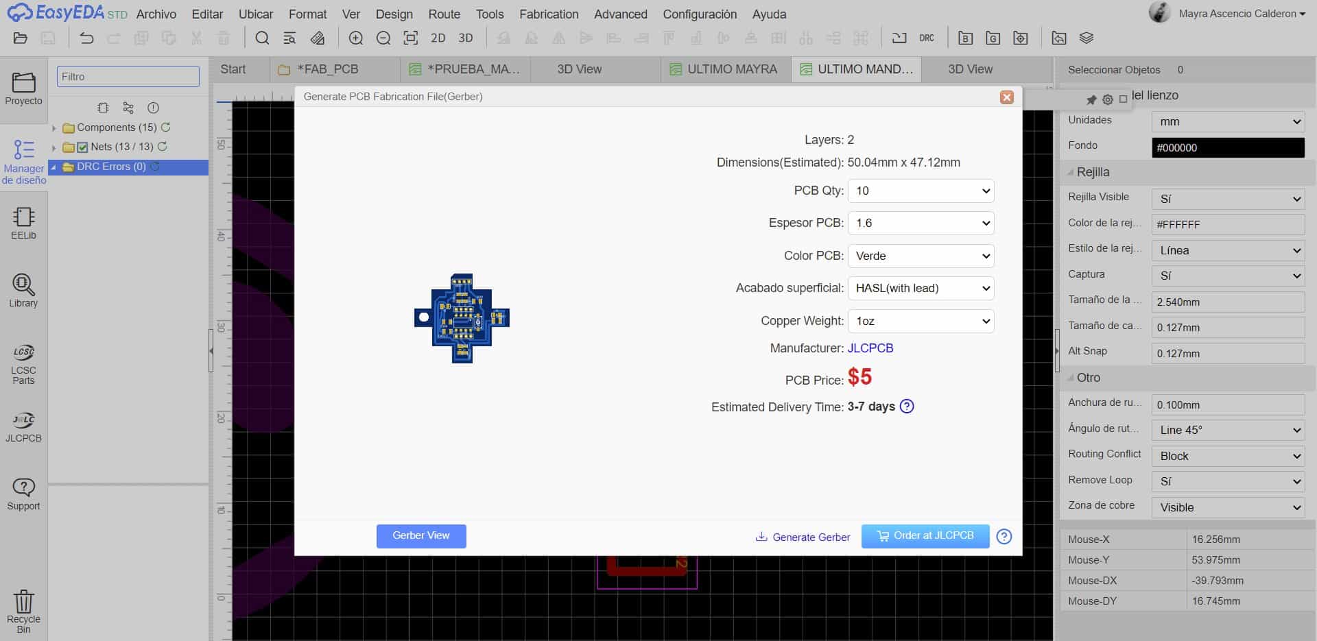
Easy EDA
Easy EDA
Easy EDA
Easy EDA
Easy EDA
Easy EDA
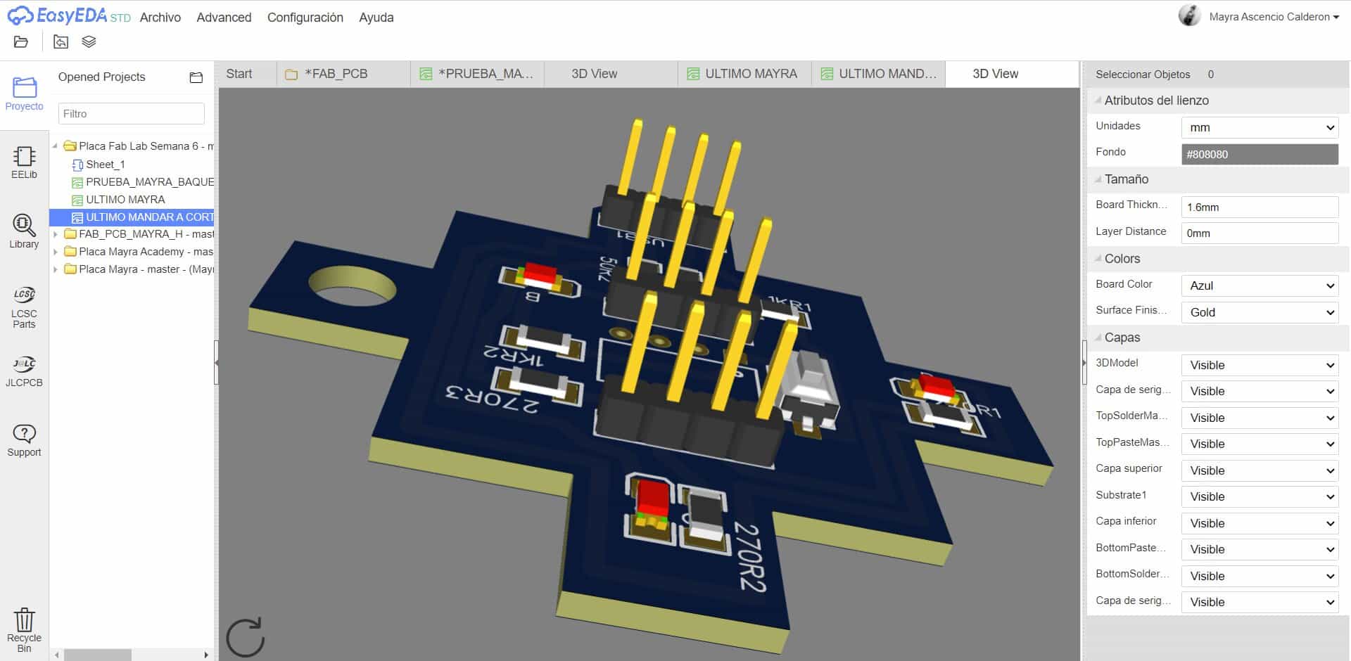
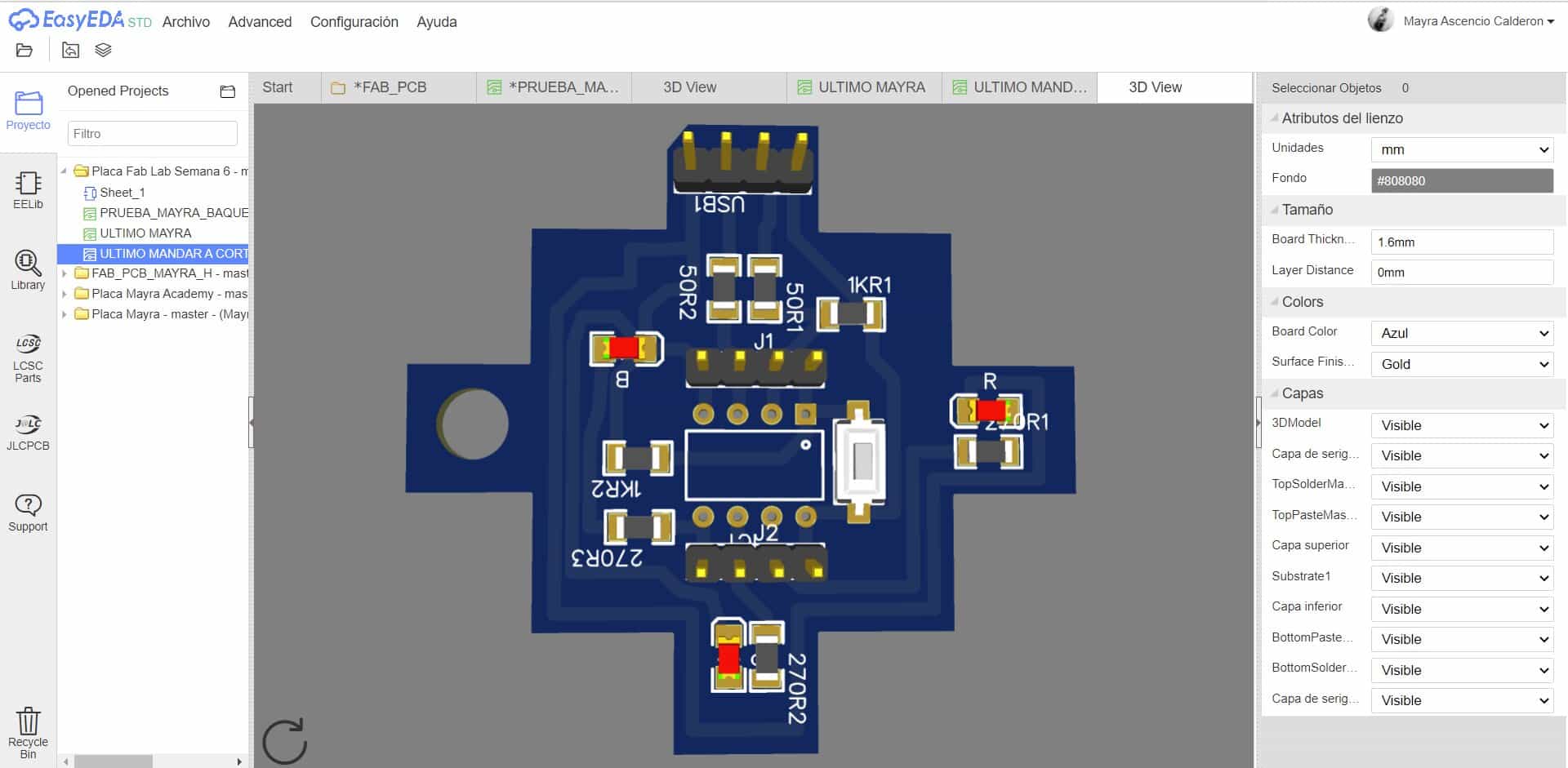
3D
3D
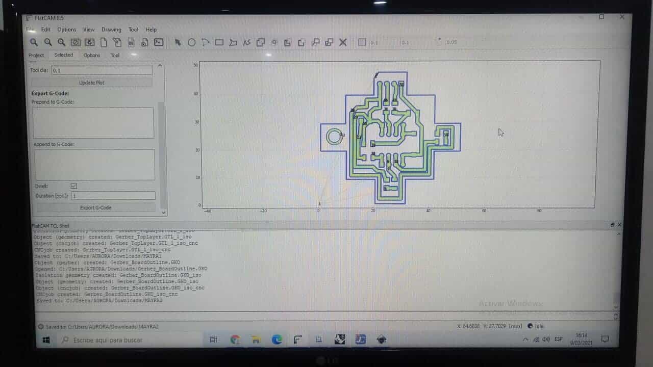
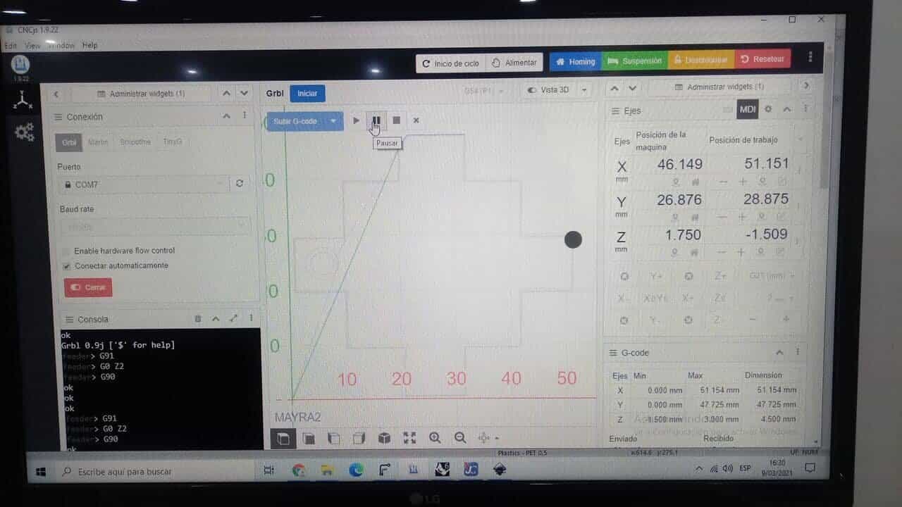
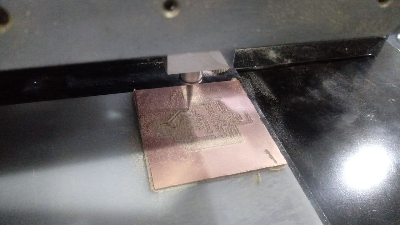
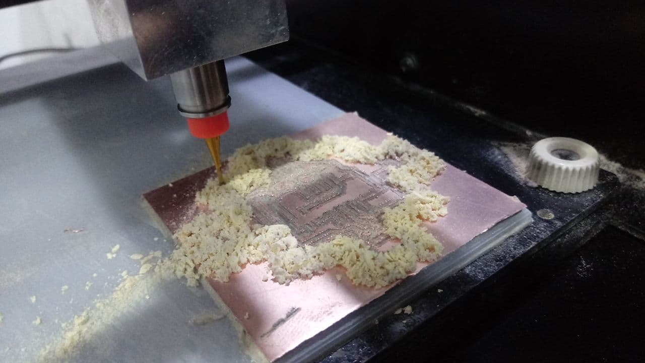
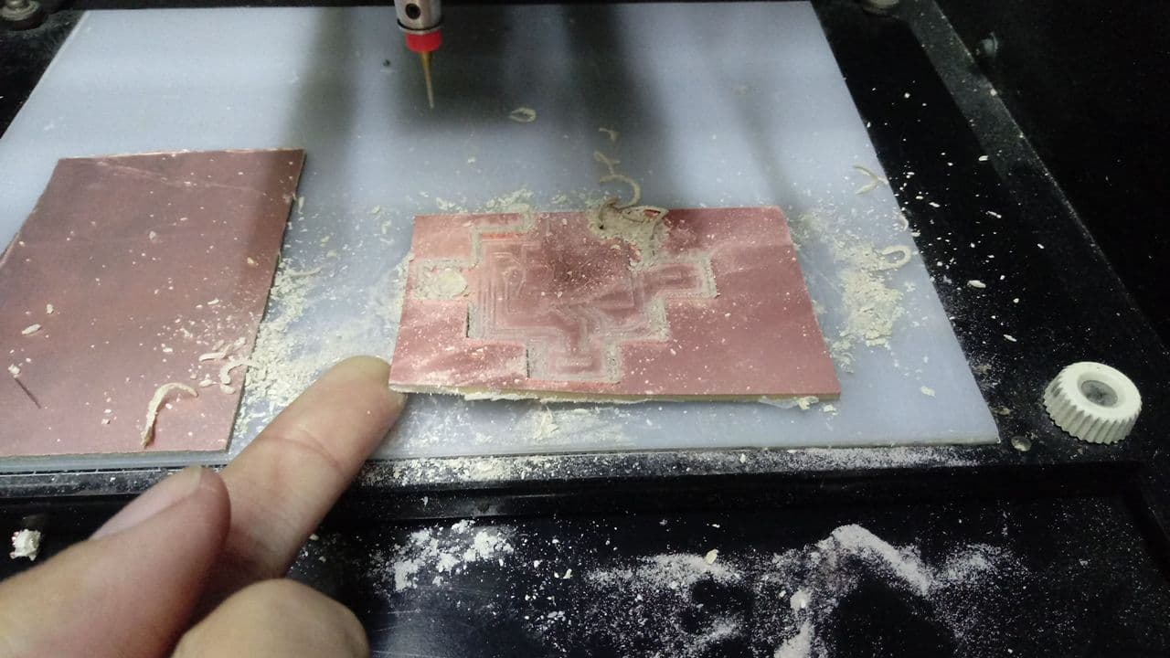
Once the design was ready I made use of two more programs, FlatCAM and CNCjs, both help me to process the files generated from EasyEDA, below I share some images. The machine I use is called Roland Modela MDX - 20 and now that it is back in the lab I was able to test my board.
FlatCAM
CNCjs
Modela
Modela
Final design
With components
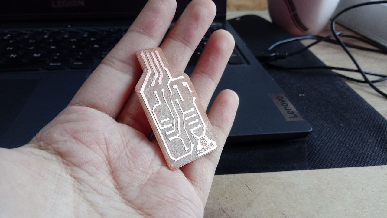
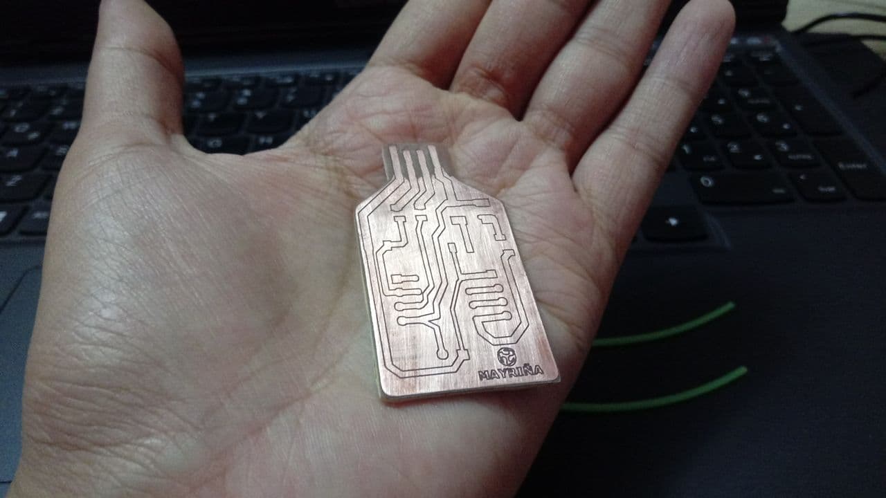
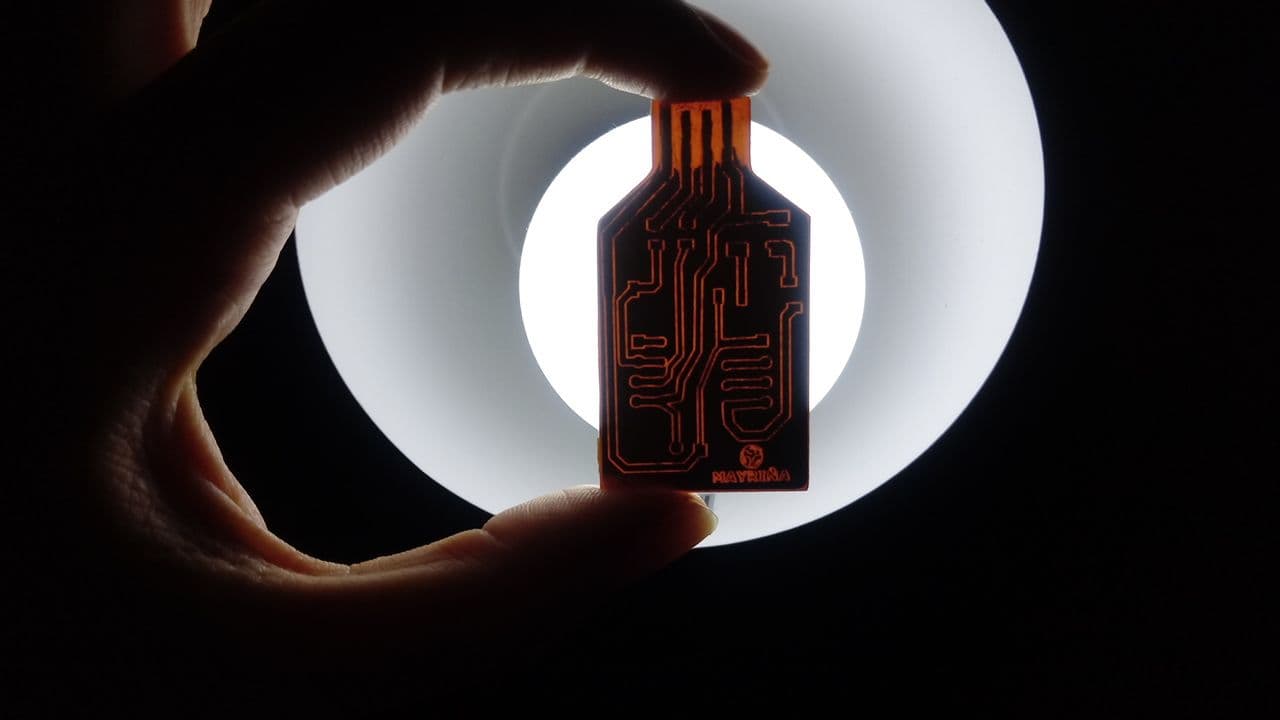
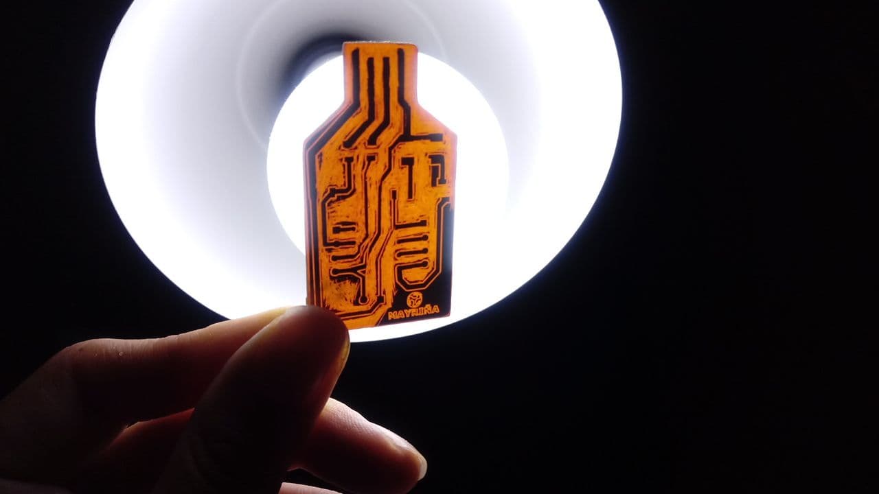
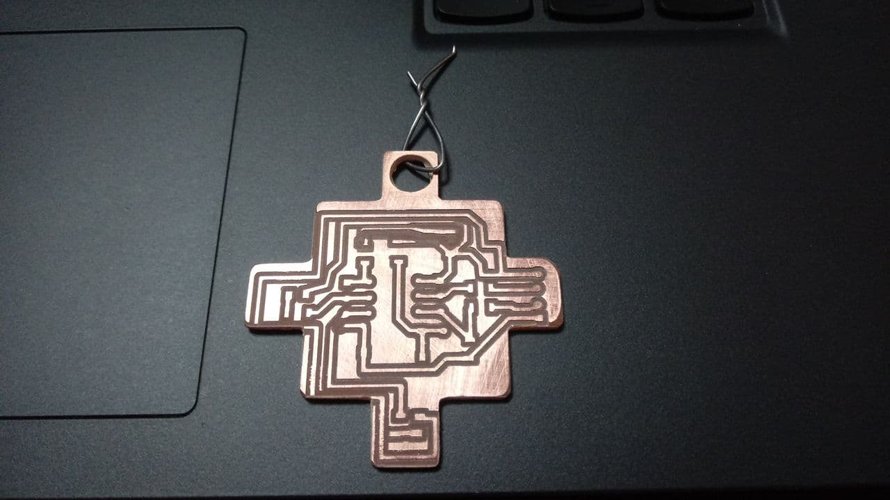
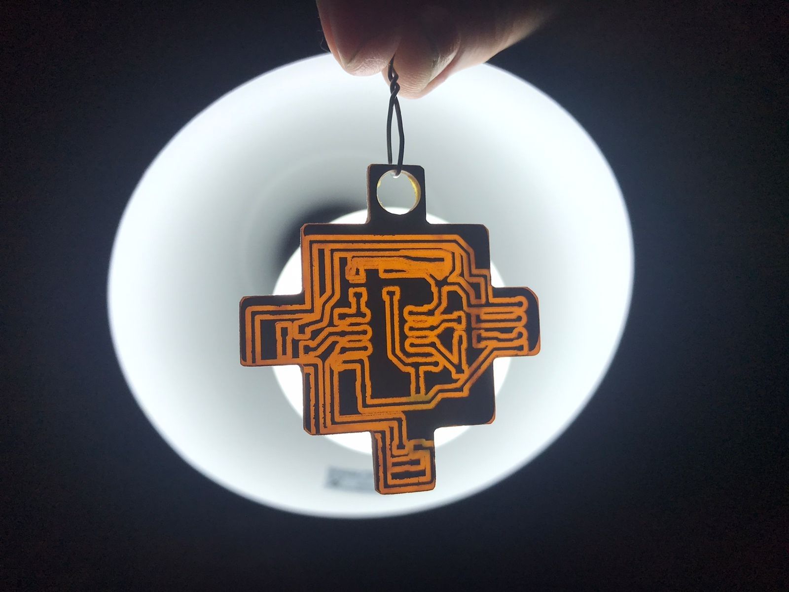
I really liked this work, designing something and then having it in your hands gave me a very nice feeling, everything we do these weeks are events that result from our own work and that's a very good thing. Here I share some final photos of the shape of my Electronic Chakana.
Electronic Chakana
Electronic Chakana
Update
Since my board did not present all the complete circuits because our MDX 20 modeling machine has a strange operation, when we send to cut, it reduces part of the board and eats some paths already milled, the solution I gave was to move my design in EasyEda and allow more space to my circuits.