4. Mechanical Design
Final Design
A. Description & Process
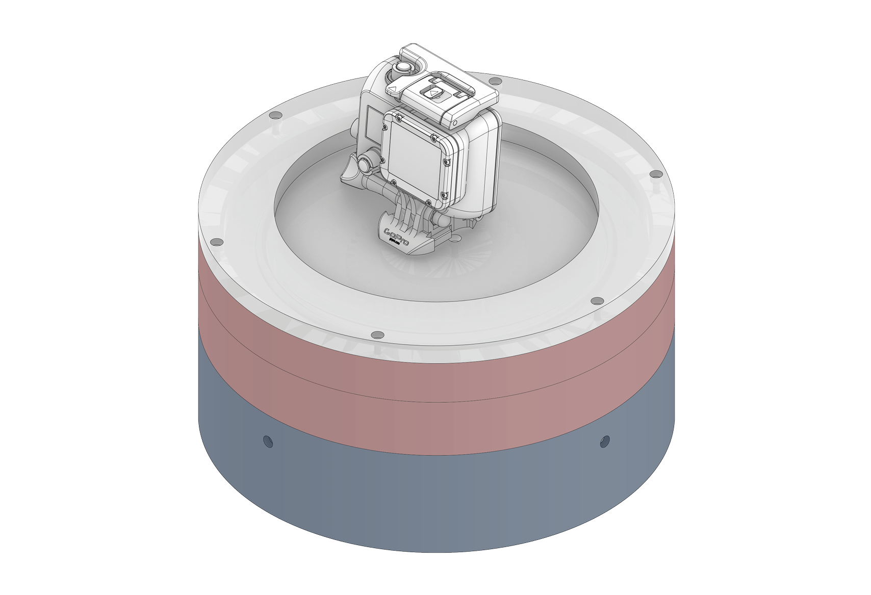
Final Design - Assembly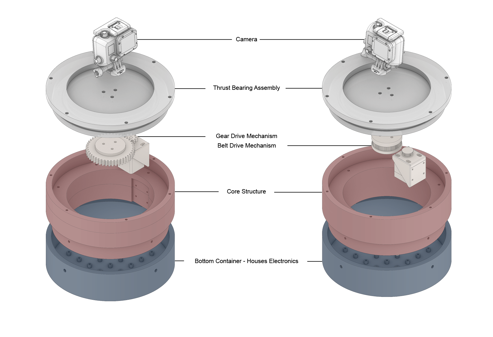
Concept - Exploded ViewB. Individual Tests
I executed a series of simple tests aiming to define production parameters for the two methods I have planned on using. These tests allowed me to familiarise myself with the processes required to produce certain details of my components.
2. Fasteners for 3D printed parts
The device is assembled by fastening multiple elements on a 3D-printed structural component. I planned on using innserts where fasteners would be frequently manipulated for adjustments, and self-threading screws to fasten parts permanently. As such, I looked to determine the optimal hole dimensions for both types of fastening mechanisms on a 3D printed plastic.
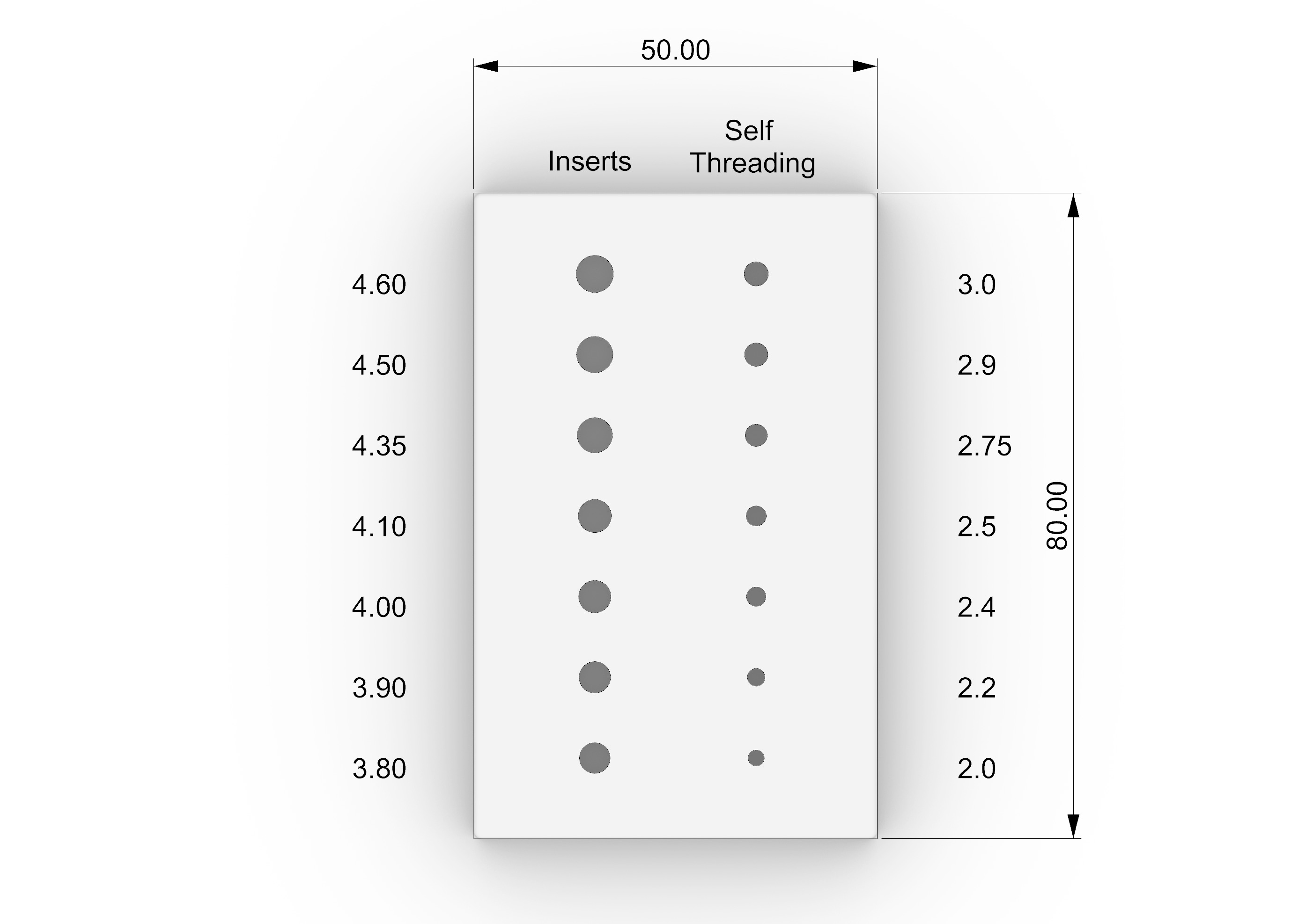
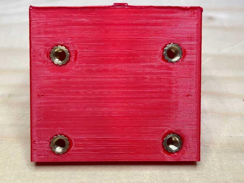
The component designed to carry out these tests is a simple cube measuring 80mm in length, 50mm in width and 8mm in thickness. Two sets of 7 holes were added to one of its faces. I worked with M3 screws as they are widely available and quite cheap. The set on the right was used with self-threading M3 screws whereas the set on the left was used with threaded heat set inserts which had a diameter of 4.6 mm. The tested hole diamaters are listed in the below image.
I printed the component on an Ender3 Pro using the following parameters
| Material | Diameter | Manufacturer | Nozzle Temperature | Bed Temperature | Infill | Layer Height |
|---|---|---|---|---|---|---|
| PLA | 1.75 mm | Smart Materials 3D | 220 | 65 | 20% | 0.2 mm |
a. Heat Set Inserts
Installing heat set inserts is done by placing the insert at the tip of a heated soldering iron and then gently pushing it into its hole. Using a soldering iron heats the material in contact with the insert’s outer surface, deforming the hole sufficiently for the it to move into its specified position. I started by testing different iron temperatures. At a temperature above 200 degrees celcius, SLA becomes sufficiently viscous to be used in a 3D printer. I therefore tested temperatures below 200, in increments of 10 degrees celcius, using a spare print which had four 4.5 mm holes. My aim was to start at 190 degrees but I had forgotten to reset the soldering iron’s temperature, which was set to 425 degrees. Nevertheless, I found that 180 degrees was optimal as I didn’t need to push the insert too hard and the material around it maintained its initial surface shape.
| Left | Right |
|---|---|
| 425 | 180 |
| 160 | 170 |
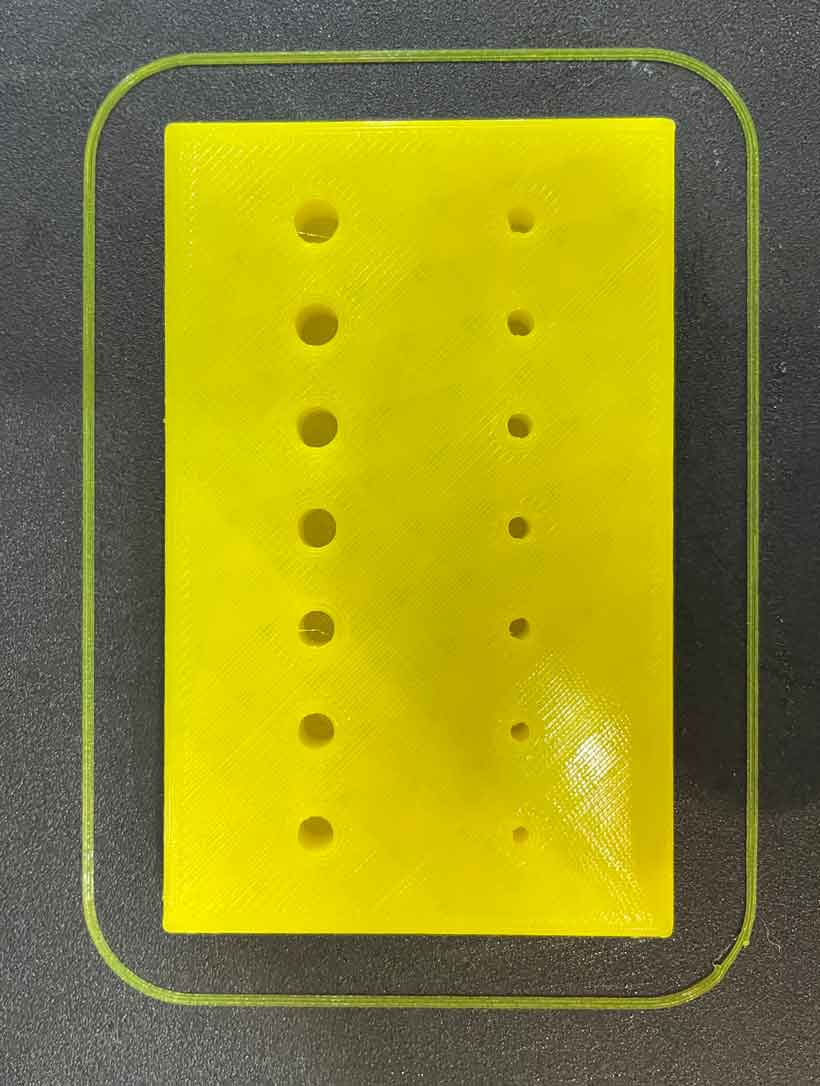
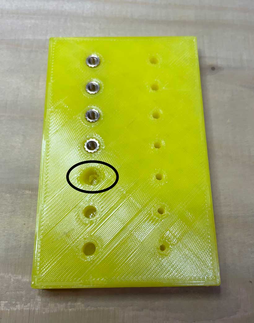
Applying what I had learned from the above, I moved to the test component. I found that a hole narrower than 4.10 mm would require a relatively large amount of force to have an insert installed within it. As shown in the below picture, the structure of the hole was significantly altered. Furthermore, the 4.35 mm hole provided the best fit with an easy installation and were therefore the dimensions I chose to use in my project.
| Top | Bottom | |||||
|---|---|---|---|---|---|---|
| 4.60 | 4.50 | 4.35 | 4.10 | 4.00 | 3.90 | 3.80 |
b. Self-Threading Screws
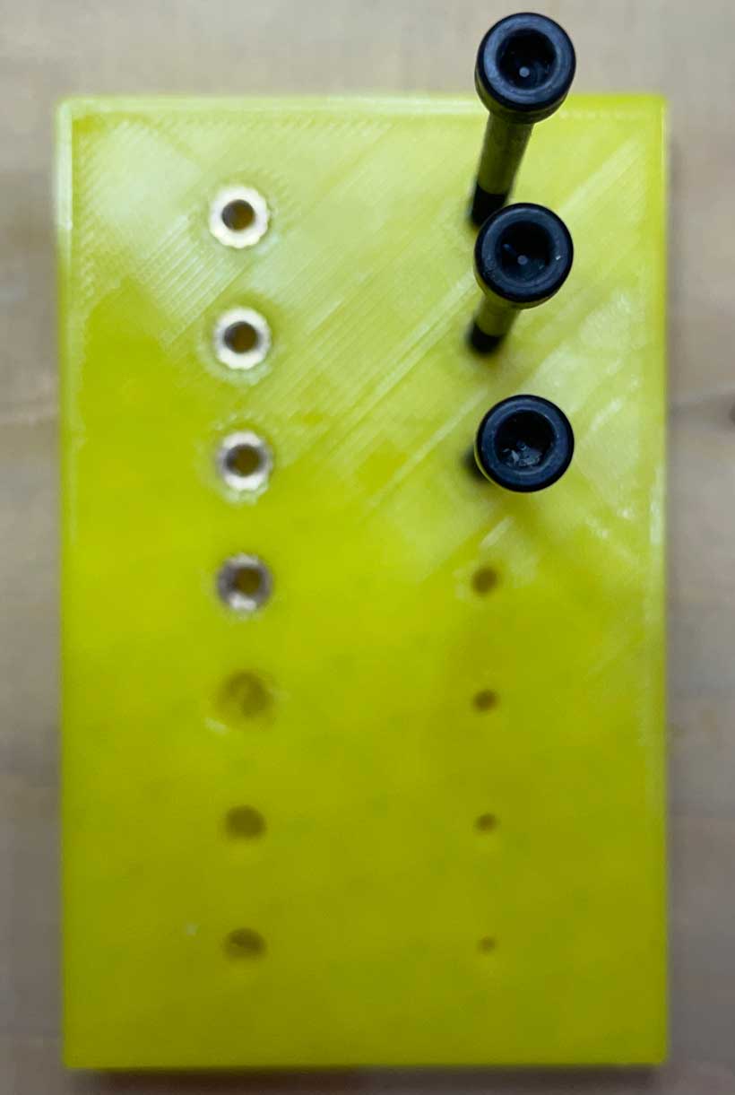
This part of the test was straight-forward. I simply tried inserting a fastener in each hole, starting from the widest ones., until I reached a hole that was too narrow for the screw to fit in. I found that 2.75 millimetres would provide the optimal diameter as it was the smallest value in which a screw could fit.
| Top | Bottom | |||||
|---|---|---|---|---|---|---|
| 3.00 | 2.90 | 2.75 | 2.50 | 2.40 | 2.20 | 2.00 |
c. Summary
In short, I used the following dimensions for fastener related holes
| M3 Screw - Head Diameter | M3 Screw - Head Length | M3 Screw - Shaft Diameter | M3 Insert - Diameter | M3 Insert - Length |
|---|---|---|---|---|
| 6 mm | 3.5 mm | 3.2 mm | 4.10 mm |
3. Component Design & Production
All components, except for the motor mount, were primarily designed in grasshopper. This proved to be useful as it enabled me to alter specific dimensions easily
a. Thrust Bearing
The thrust bearing is the central component of the device. It is responsible for providing the base panning motion of the camera. A lot of thought has gone into determining how to design a fully contained mechanism that allows for an enclosed system, and what materials to make it of. Having discussed this with my instructors, I settled on milled 10mm thick acrylic as it would yield a smooth and solid surface finish. This decision was mainly driven by the need for the panning motion to be as uniform and silent as possible. I also purchased bearing balls with a diameter of 6 millimetres. The radius of the raceways was calculated by selecting a specific number of balls (89 here).
The designed mechanism is composed of three plates. The central plate provides the panning motion whereas the top and bottom ones hold everything in place. The latter two are attached onto a supporting structure with M3 screws.

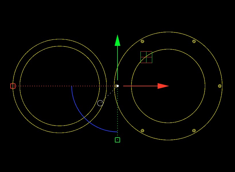
I milled the acrylic plates using the above curves. The milling files were prepared in RhinoCAM. The table below lists the characteristics of the tools and operations made.
| Operation | Tool | Feed | Speed | Layer Depth |
|---|---|---|---|---|
Raceways - Profiling |
6mm - Ball | |||
M3 Screw Head - Slotting |
3mm - Flat | |||
M3 Screw Shaft - Slotting |
6mm - Flat | |||
Plate Outline - Profiling |
6mm Flat |
| Tool | 3mm - Flat | 6mm - Flat | 6mm - Ball |
|---|---|---|---|
Holder Diameter |
30 mm | ||
Holder Length |
45 mm | ||
Shank Diameter |
6 mm | ||
Tool Length |
35 mm | ||
Shoulder Length |
27 mm | ||
Flute Length |
27 mm | ||
Tool Diameter |
6 mm |
The resulting pieces are shown below.
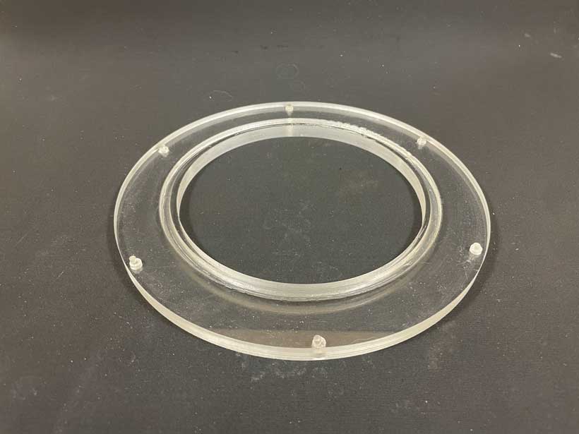
Bearing's top acrylic plate 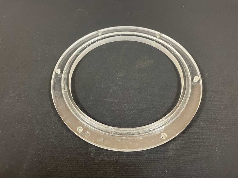
Bearing's bottom acrylic plate 
Bearing's central acrylic plate 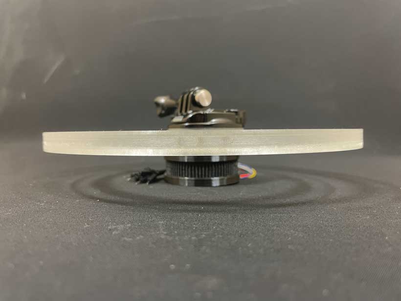
Side view of bearing's central acrylic plate b. Core Structure
The core structure is the component on which all other components are attached. It has M3 inserts to attach the acrylic plates and the bottom casing. Furthermore, it also features a slot for the motor mount.
The core structure was printed in a Carbon Fiber / PETG filament.
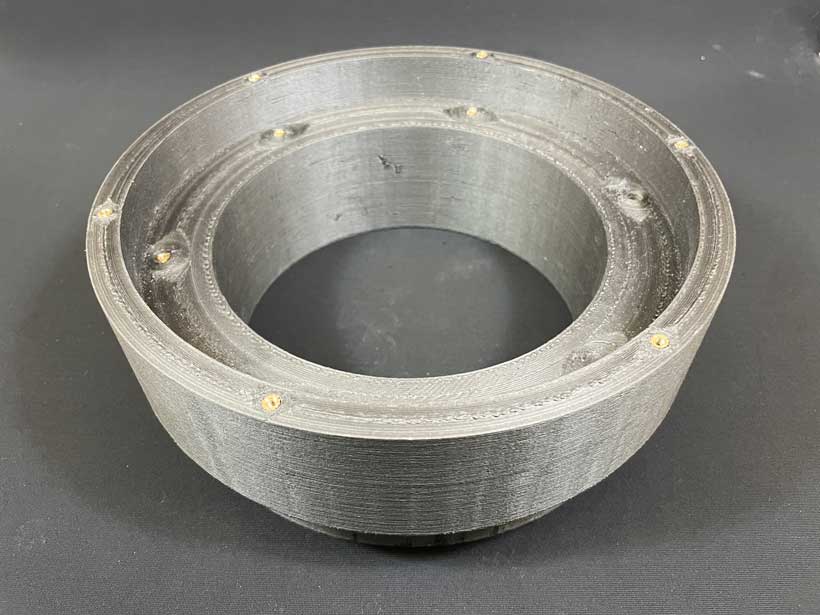
Top View of Core Structure 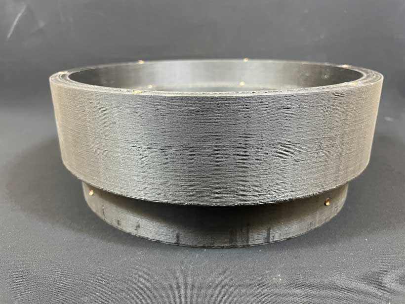
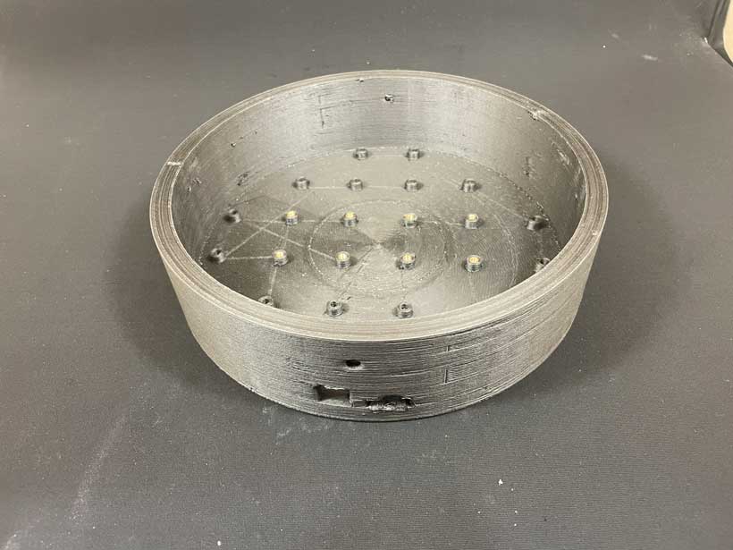
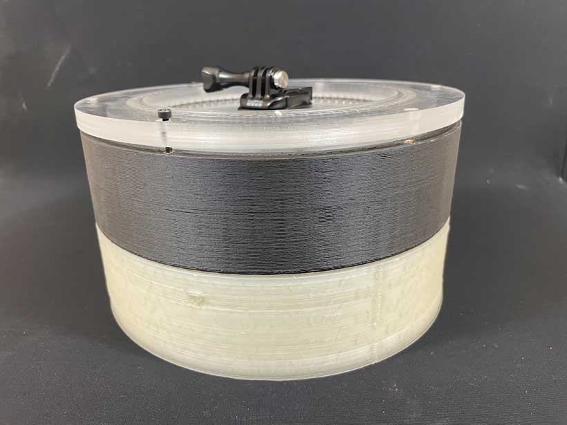
Side View of Core Structure c. Bottom Casing
The bottom casing seals the device into a fully contained unit. It possesses a grid of M3 inserts on which electronic components can be attached. The grid is standardised with the distance between inserts being set at 35 millimetres. This gives the system a certain modularity with regards to the modification of the electronic components. New circuit boards can be easily added with little dimensional constraints, making the device a development workbench onn which new technologies and methods can be tested before redesigning and repackaging the whole solution. The casing also features two openings which allow for DC power and FTDI connections to provide power and a serial connection, respectively.
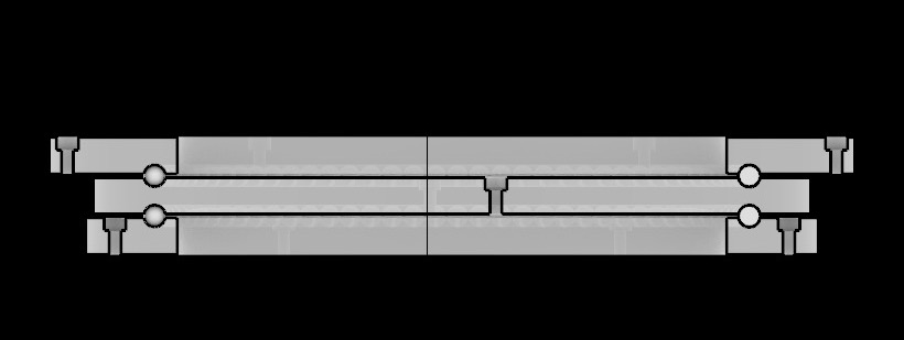
Similarly to the core structure, the bottom casing was printed in a Carbon Fiber / PETG filament. The tolerance wasn’t set properly. As such, this bottom casing fights too tightly onto the structure. As shown below in section 4. I have not pushed it all the way through to its intended position to avoid having it get stuck.
d. Driven Pulley
The driven pulley was designed in grasshopper. It is fastened to the centre of the central bearing plate with 3 M3 screws through threaded inserts. On its bottom face is an open rectangular volume in which a Magnetometer/Compass can be installed. In the case of this project, the volume is made to fit a BN880 GPS/Compass module.The driven pulley has a total of 80 teeth. On the other hand, the driver pulley attached to the motor has 20 teeth. This gives the belt drive mechanism a reduction ratio of 1:4.
The diameter of the pulley was determined by taking into consideration the I also needed to take into consideration the belt length dimensions available on the market as those were standardised. I went for a combination of a 52 millimetres wide pulley with a 200 millimetres GT2 time belt, calculated using the below equation
L = (d₁ * π / 2) + (d₂ * π / 2) + 2D + ((d₁ - d₂)² / 4D)
The pulley was printed in a black SLA filament using the following settings.
| Material | Diameter | Manufacturer | Nozzle Temp | Bed Temp | Infill | Layer Height |
|---|---|---|---|---|---|---|
| PLA | 1.75 mm | SmartMat3D | 220 | 65 | 20% | 0.2 mm |
One particular issue I have encountered with the designed pulley is that it isn’t entirely compatible with the G20 timing belt it was designed for. At high speeds and high torque resistance, the belt would slip, stopping the movement of the bearing such as in the high friction areas of the bearing, which didn’t help. I believe that this is due to the distance separating the teeth being shorter than required for the belt used. I’ll need to modify the design program for future iterations.
e. Motor Mount
I had to design a motor mount which would allow me to adjust the position of the motor simply by oppening the device from the bottom casing. Inspired by an example shown to me by my instructor Edu, I designed a rail system on which the actual motor mount would slide. M3 screws would be used to lock the mount in a given position. The rails would be attached on the inside of the device’s core structure. This adjustable system would for the tension in the belt to be adjusted as desired. The mount assembly was designed last, customised to work with the core structure as it is.
The mount’s components were printed in a black SLA filament using the following settins. Pictures of the resulting bodies are shown below.
| Material | Diameter | Manufacturer | Nozzle Temp | Bed Temp | Infill | Layer Height |
|---|---|---|---|---|---|---|
| PLA | 1.75 mm | SmartMat3D | 220 | 65 | 20% | 0.2 mm |
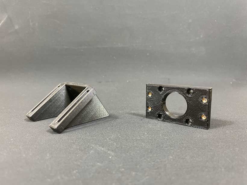
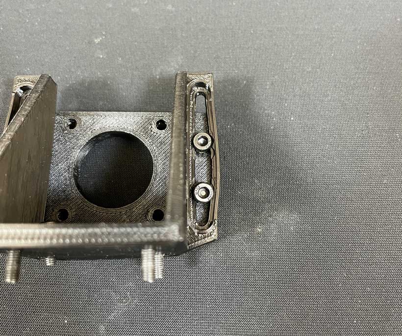
Motor head (right) rails (Left) 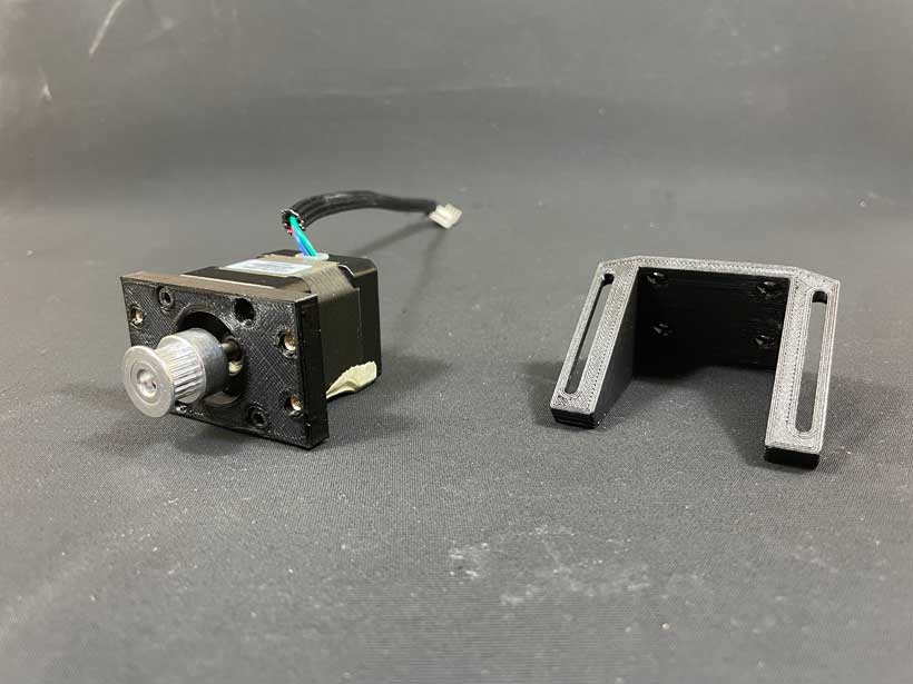
Motor head assembled onto motor (left) rails (right) 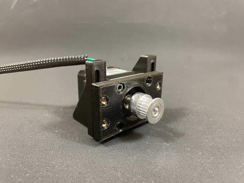
Assembled motor mount front view 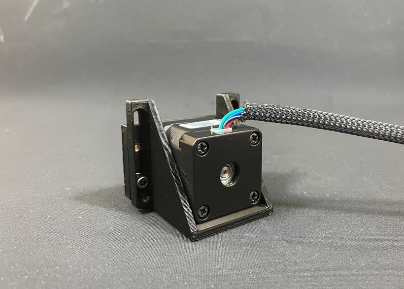
Assembled motor mount back view 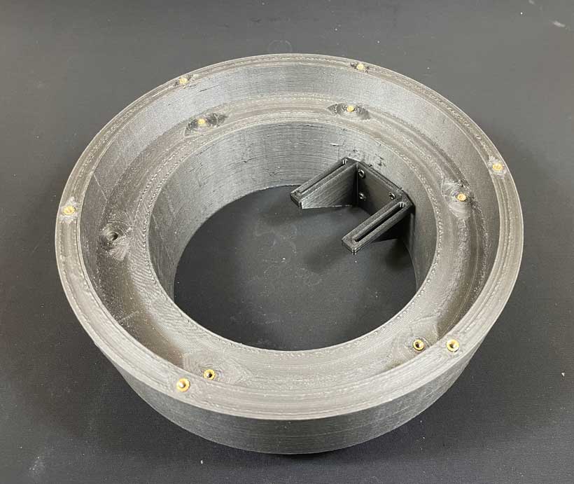
Rails mounted onto the core structure 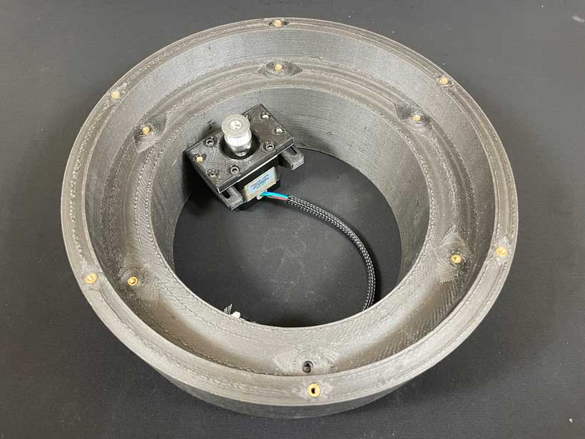
Mount Assembly mounted onto the core sturcture All and all, this design proved to be very effective. However, I noticed that, over time, the rails would deform and start wrapping around the head of the screws. While this had no imediate effect on the usability of the mount, it might compromise the the component if any further structural deformations occur. I will need to review the design for future iterations.
Rail Deformation 4. Final Result
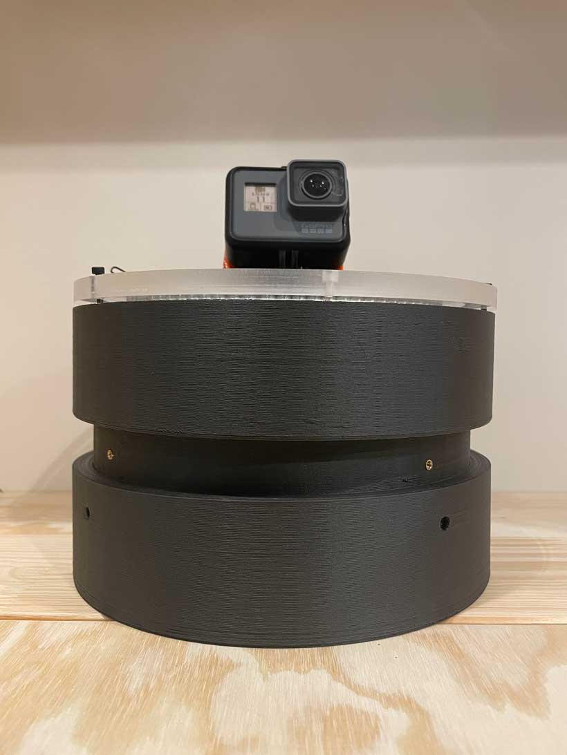
For the sake of visualising the proportions of the device, I also printed the casing in PLA.
Files
References
https://formlabs.com/blog/adding-screw-threads-3d-printed-parts/