2. Computer Aided Desgin
Assignment
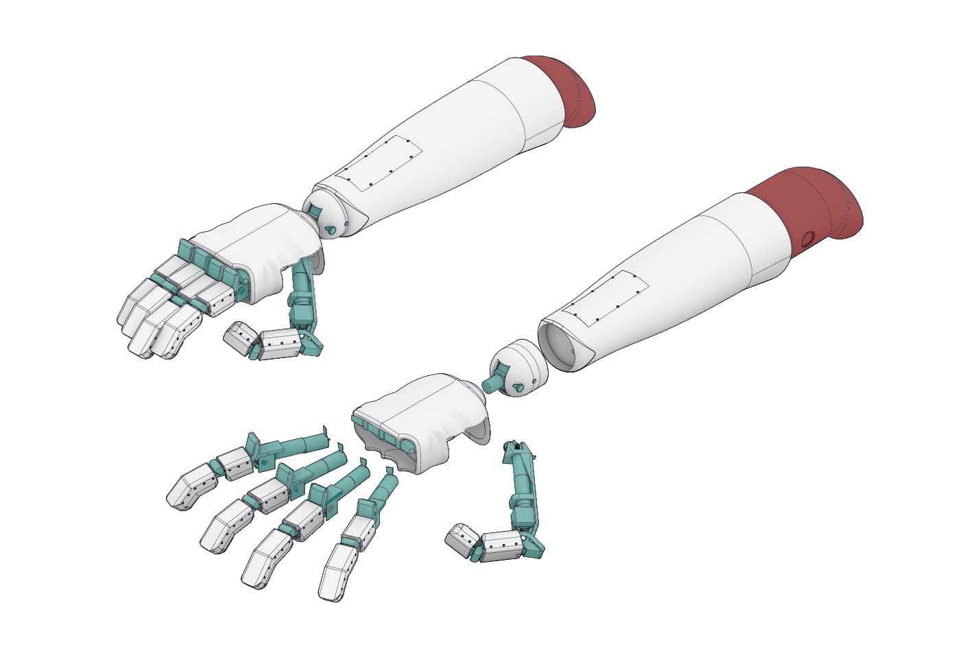
- Model (raster, vector, 2D, 3D, render, animate, simulate, … all possible) a possible final project.
- Compress images and videos.
- Post on class page.
A. 3D
I already have quite a bit of experience using CAM/CAE/CAD tools. During my undergraduate studies, I worked with SolidEdge and Ansys to design mechanical components, analyse their reaction to different stresses, and having them manufactured. Furthermore, I also used AutoCAD to draw floor plans and section/elevation drawings in my last job. Finally, I learned the basics in Rhino, Illustrator and Photoshop for personal projects.
I therefore looked to try new softwares in order to build a better understanding of the tools available. To that end, I structured my approach to be the following (These were not completed in the described Order):
-
1. Sketch Based Modelling
1. Sketch the top or/and side view of components of an object in 2D. 2. Use the various functions available to create a 3D model of that object -
2. Freeform Modelling
1. Rebuild the model previously created using a freeform modelling approach -
3. illustration
- Create an illustration using both Raster and Vector based tools.
-
4. Rendering and Coloring
1. Render All models previously produced in monochrome colors. 2. Use Raster or Vector editing tools to add colors to the renders. -
5. Animate object in Blender
-
6. Simulate model’s reaction to stresses
-
7. Compress all documentation videos and images
1. Fusion 360
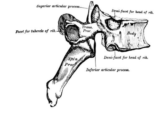
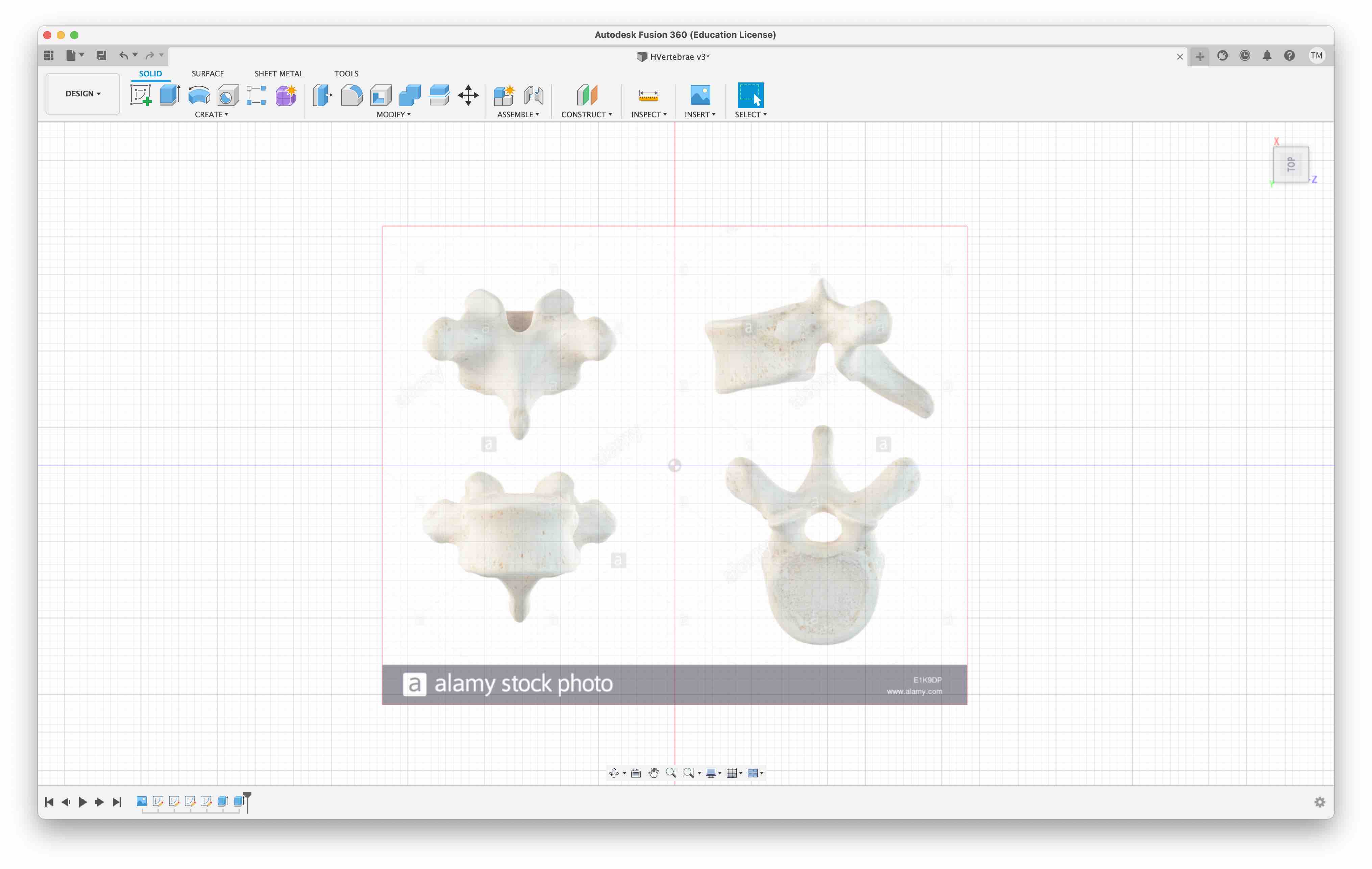
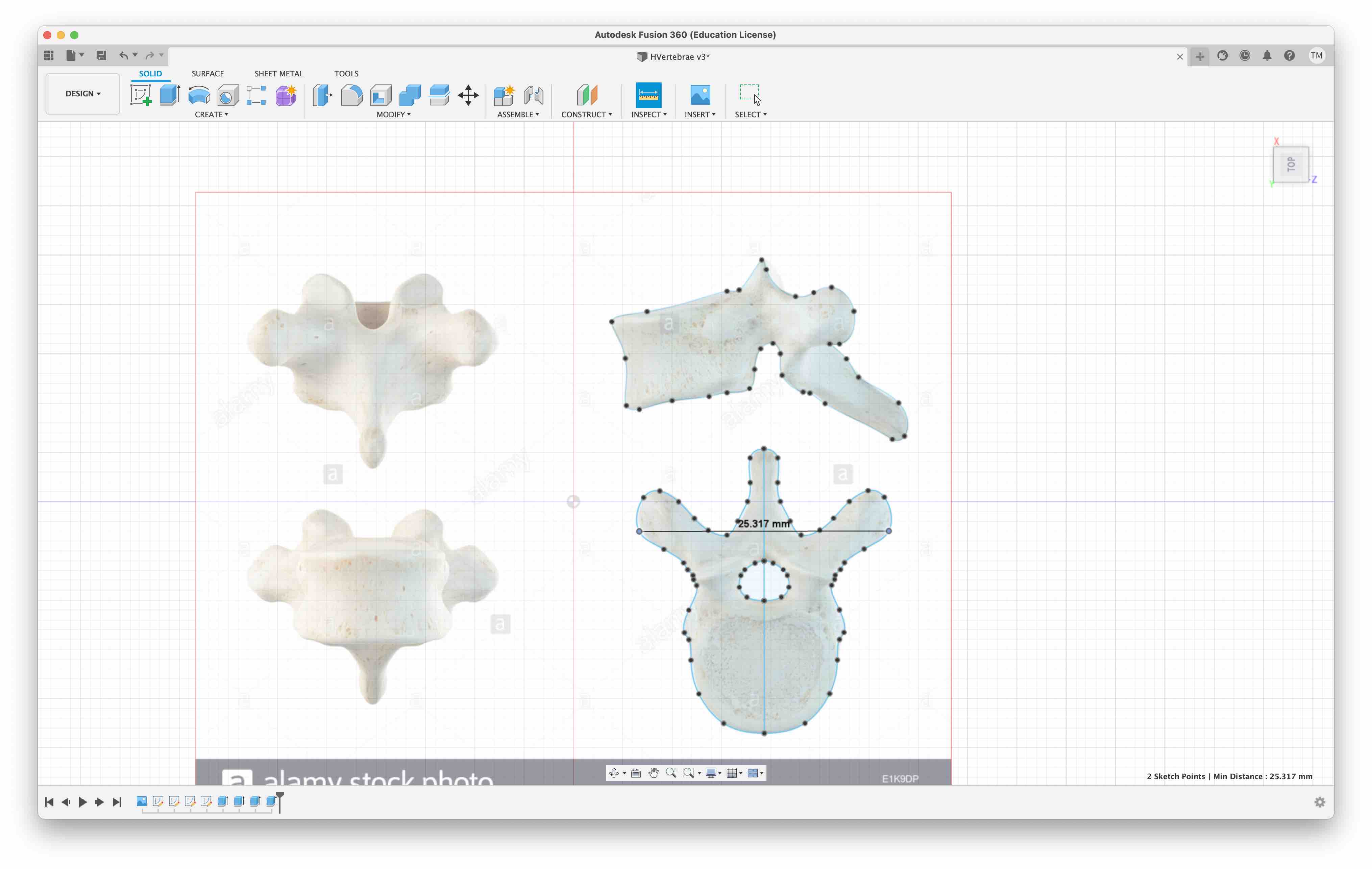
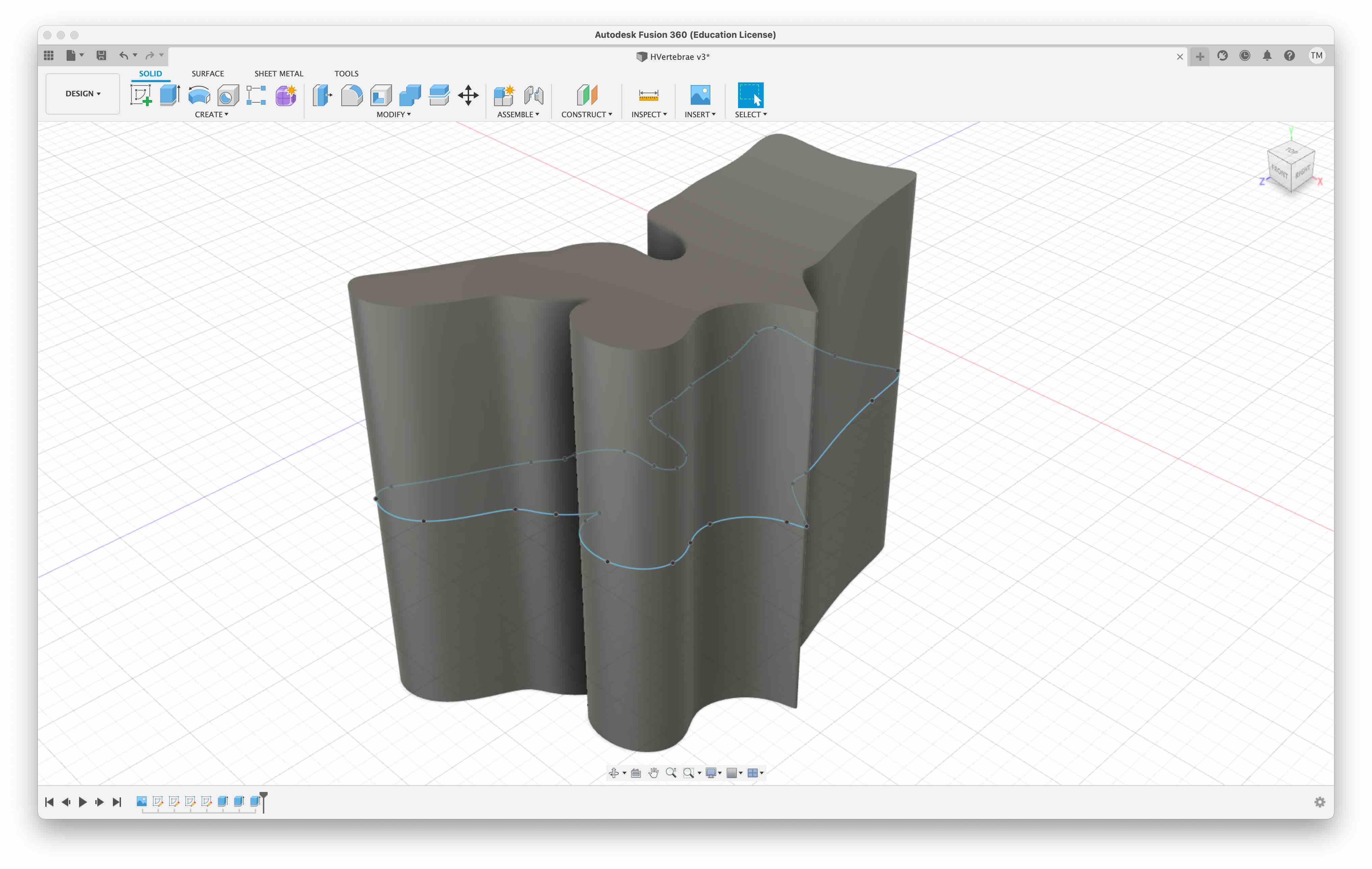
I set out to model a human vertebrae. The complex geometry of a vertebrae made it an enticing challenge. To begin, I imported lateral and top views of a thoracic vertebrae in Fusion360 and set them as canvases. Scaling the pictures to real dimensions wasn’t important as I was more concerned with modelling in the proper proportions. Fusion allows modelling Solids (not MESH) and Surfaces. Both were used here.
Fusion Thoracic Vertebrae Modelling
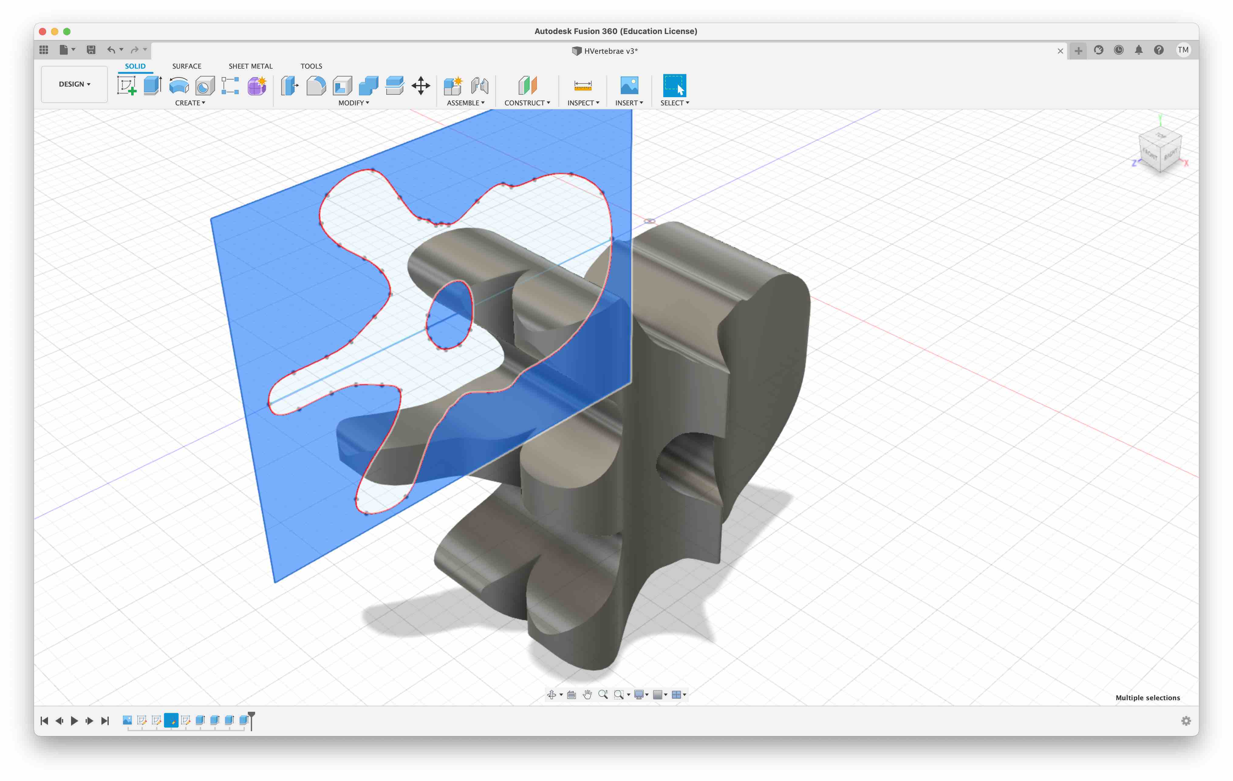
I first sketeched the profile of the side, and extruded the drawn geometry by the width measured from the canvas using the Solid tab. I then sketched the contours from the top view. Here, the geometry is almost symmetrical. I therefore sketched on half and used the Mirror function to generate the other half.
Once done, I subtracted the drawn geometry from the previously extruded solid.
Similarly to the above, I extruded the lateral and top sketches from the Surface tab tools.
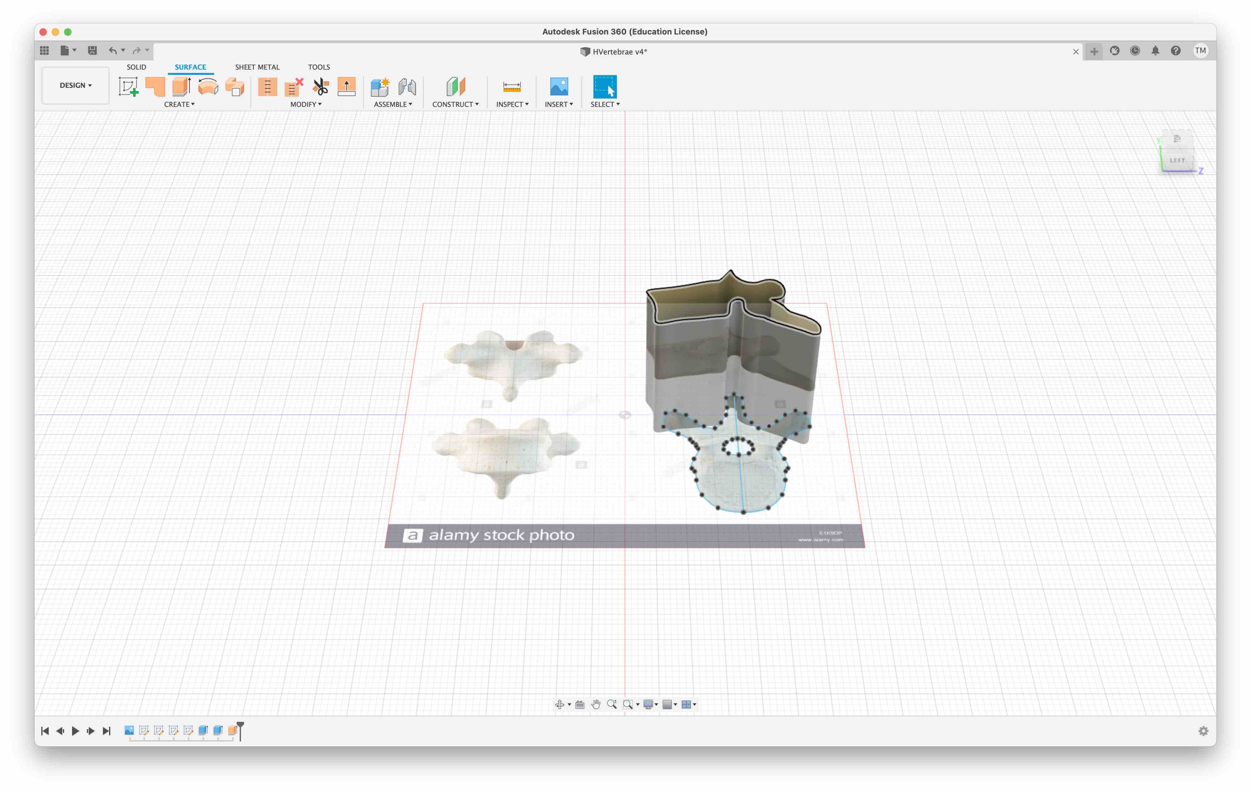
Surfaces can’t be cut directly from an extrusion operation. Instead, extra surfaces need to be trimmed using a trim tool.
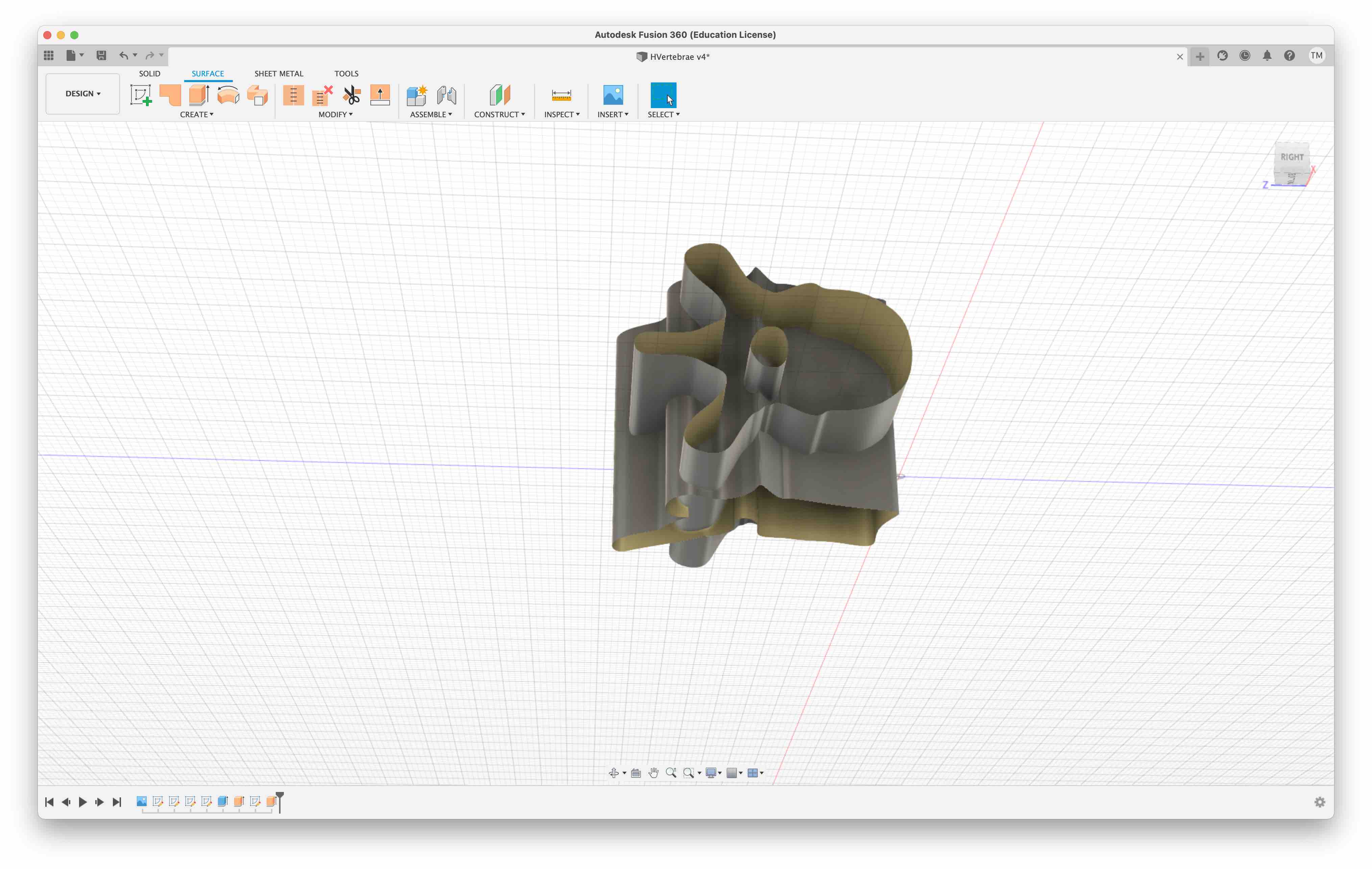
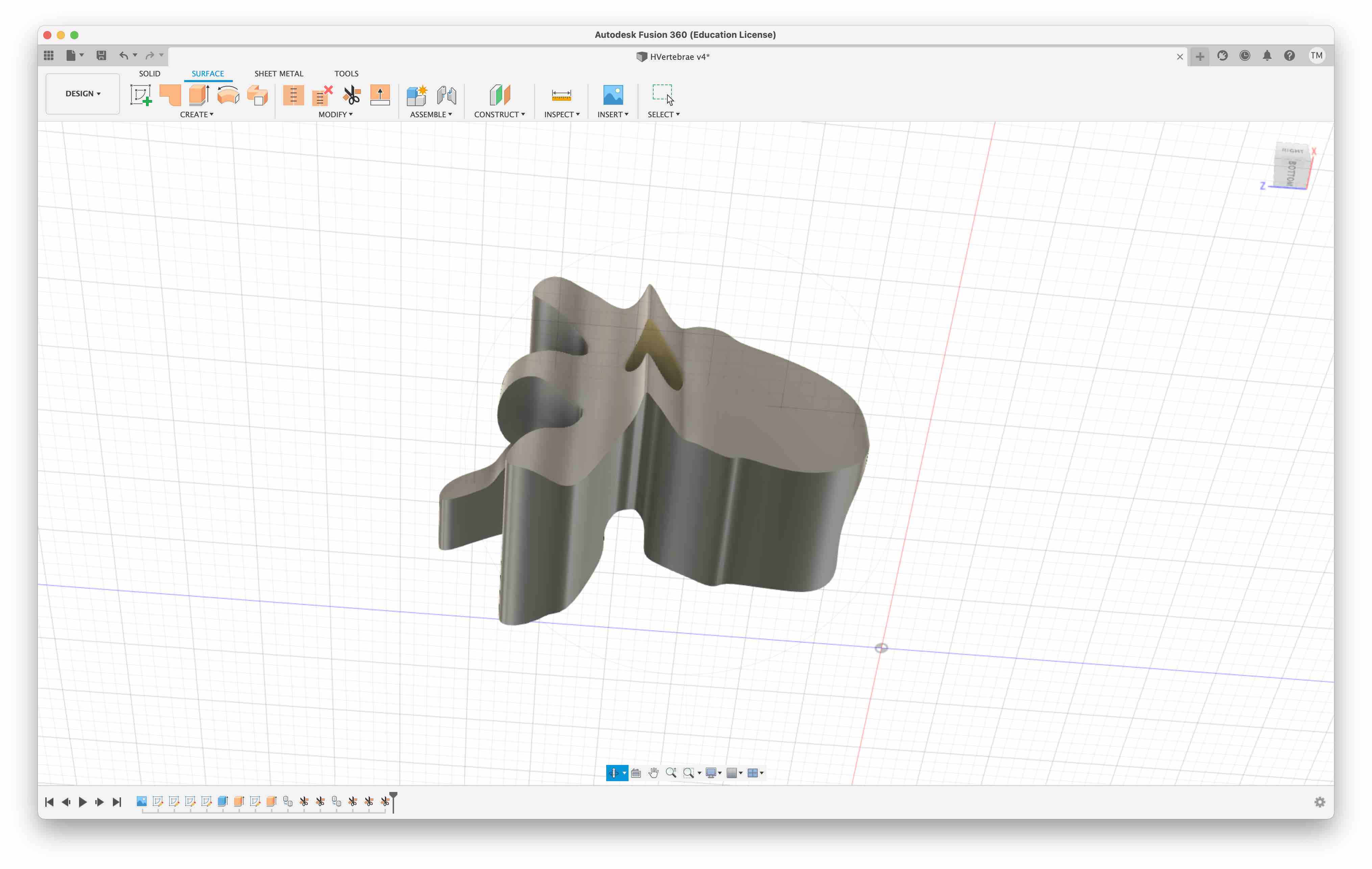
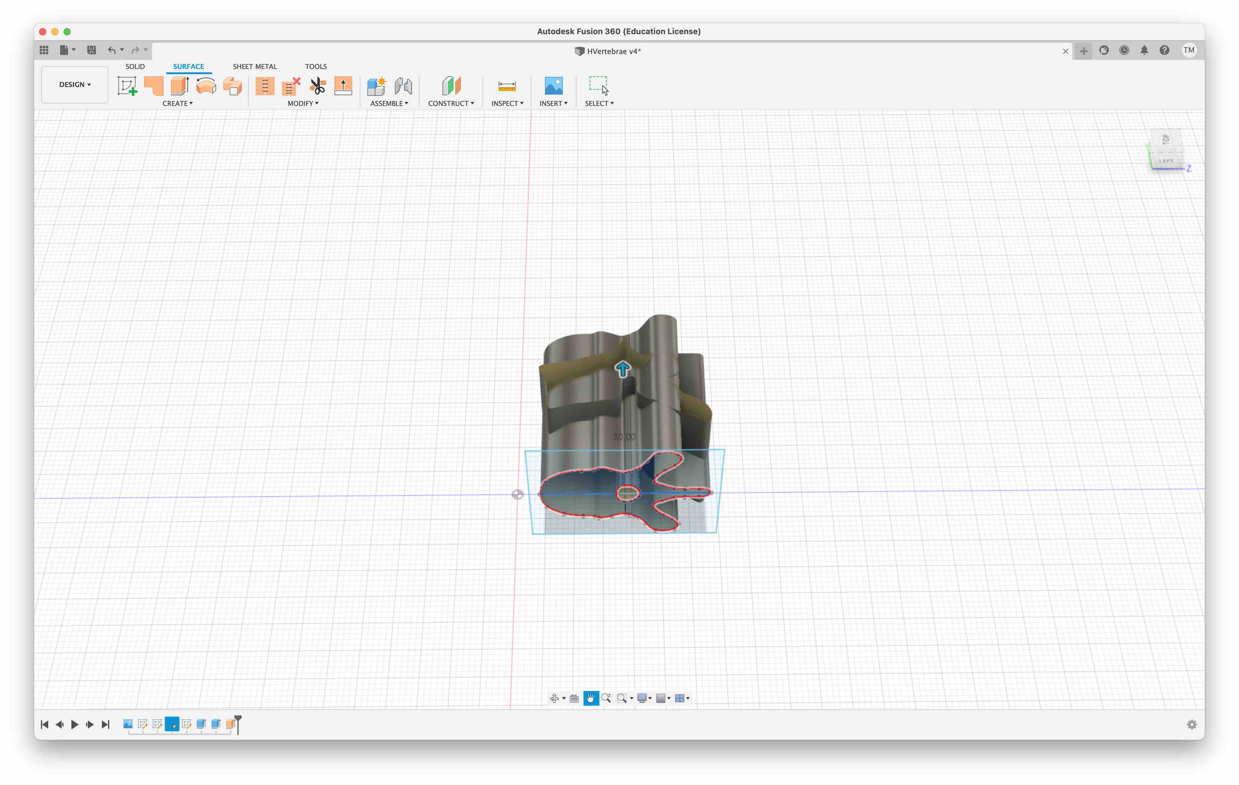
The final object can then be stitched, creating a solid object.
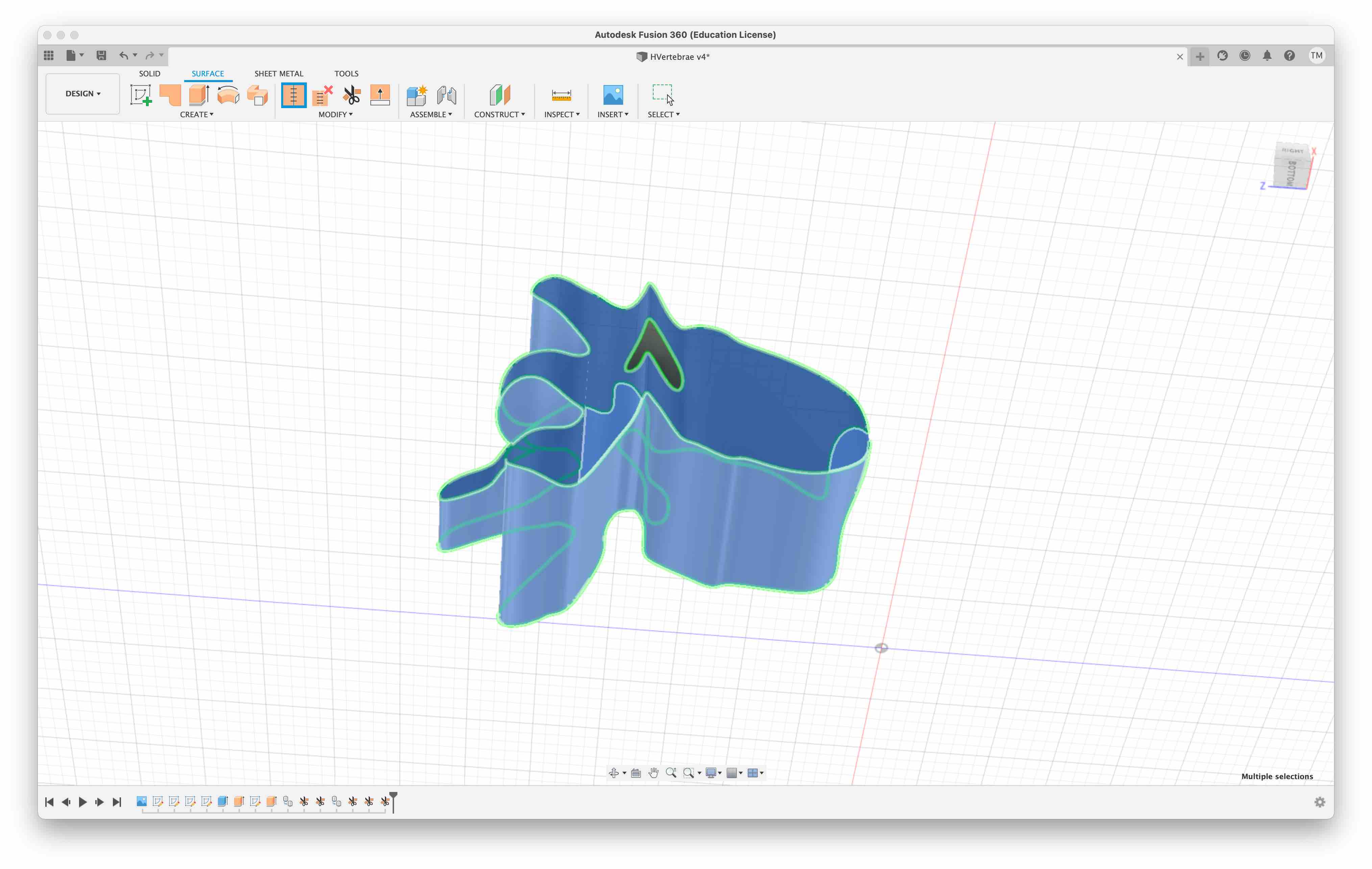
Here, I hit a roadblock. Modifying the current solid would become too tedious to complete on Fusion with my current knowledge. My solution was to export the model to Blender where I believed I would use the sculpting tools to modify to solid to the desired shape. Of the available export format options, Waveform (.obj) and STL (.stl) are compatible with blender. I created a file in both formats.
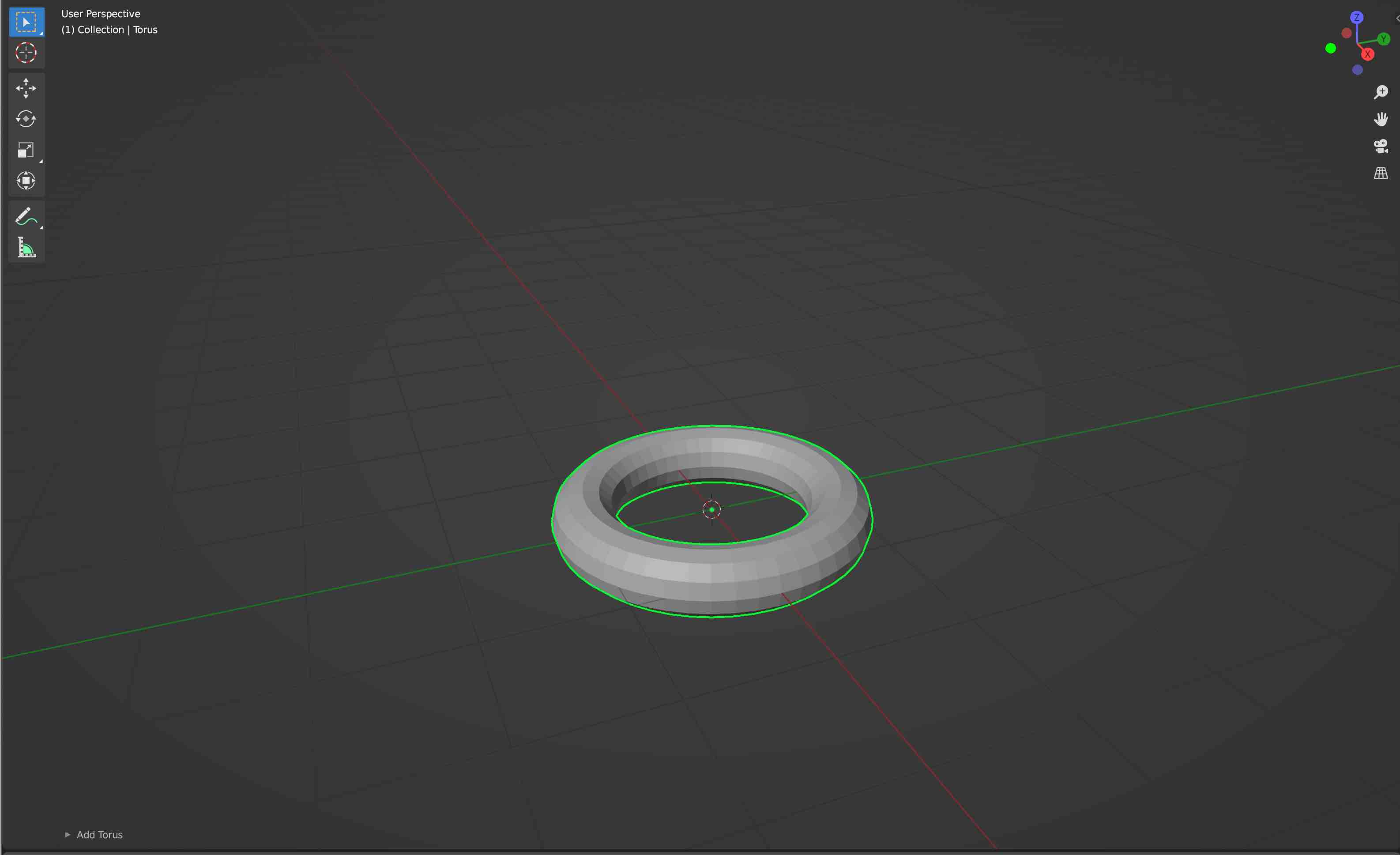
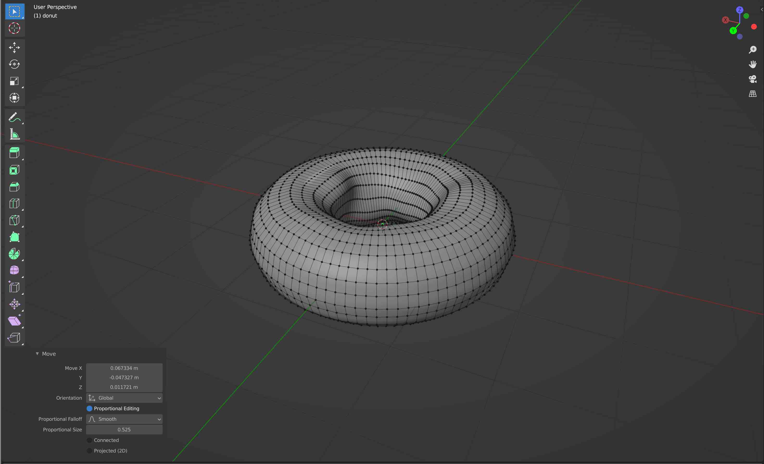
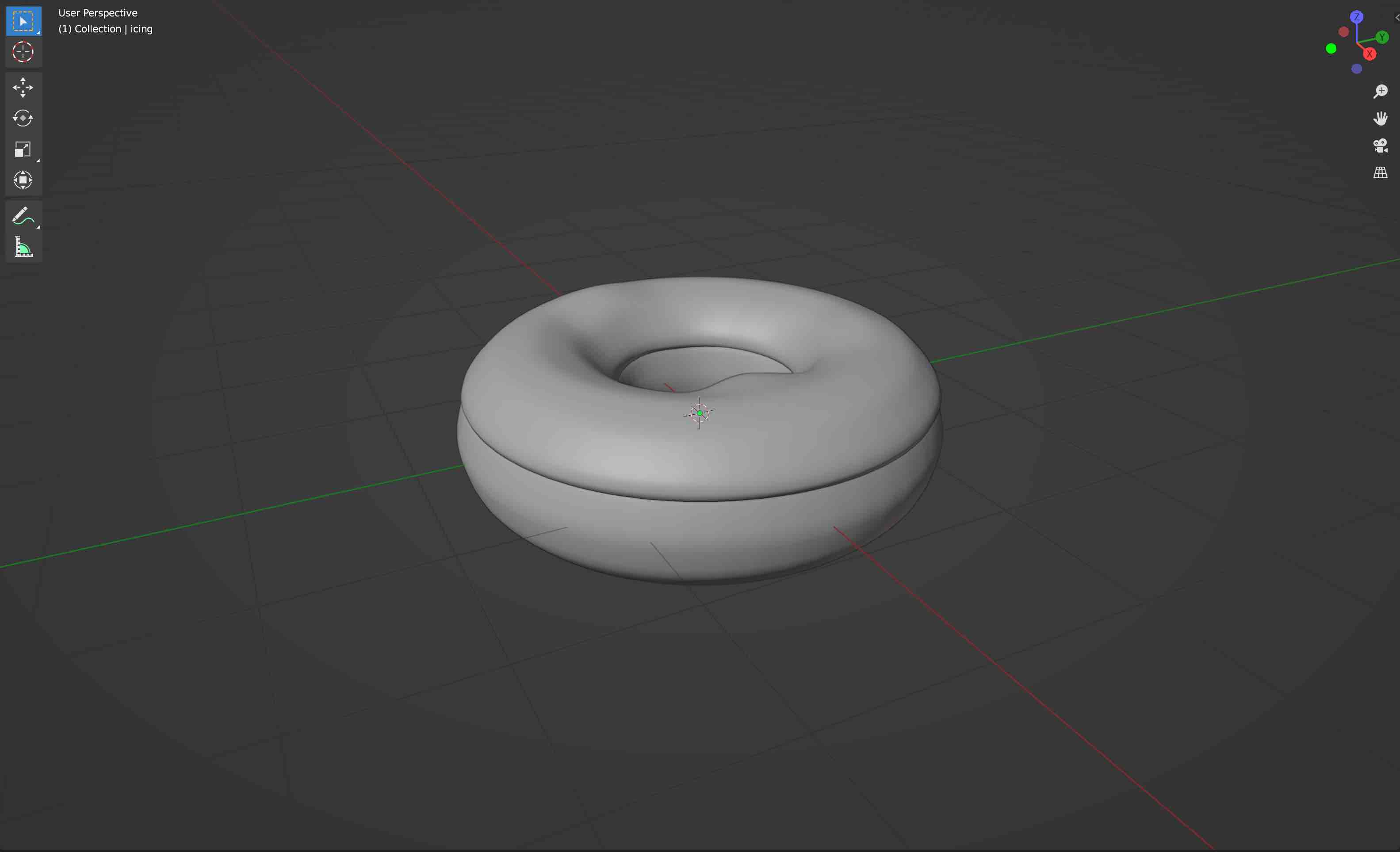
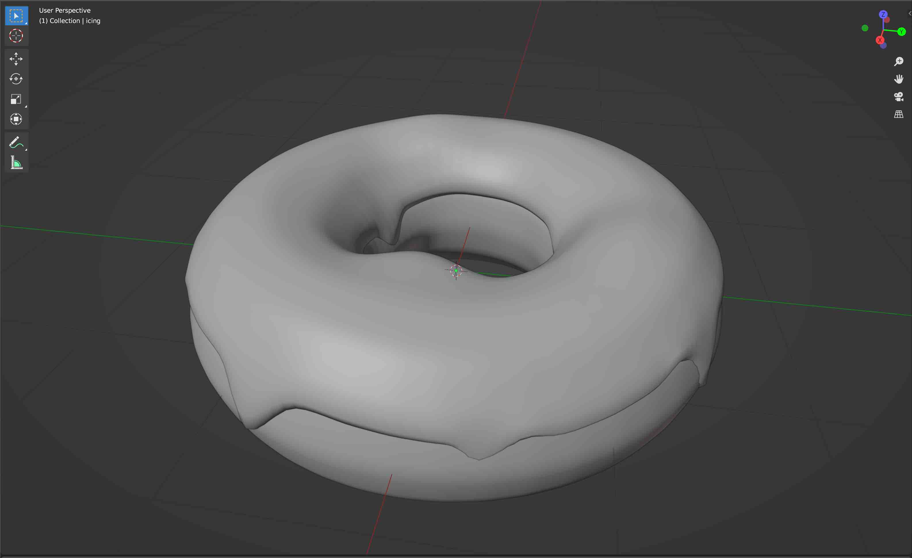
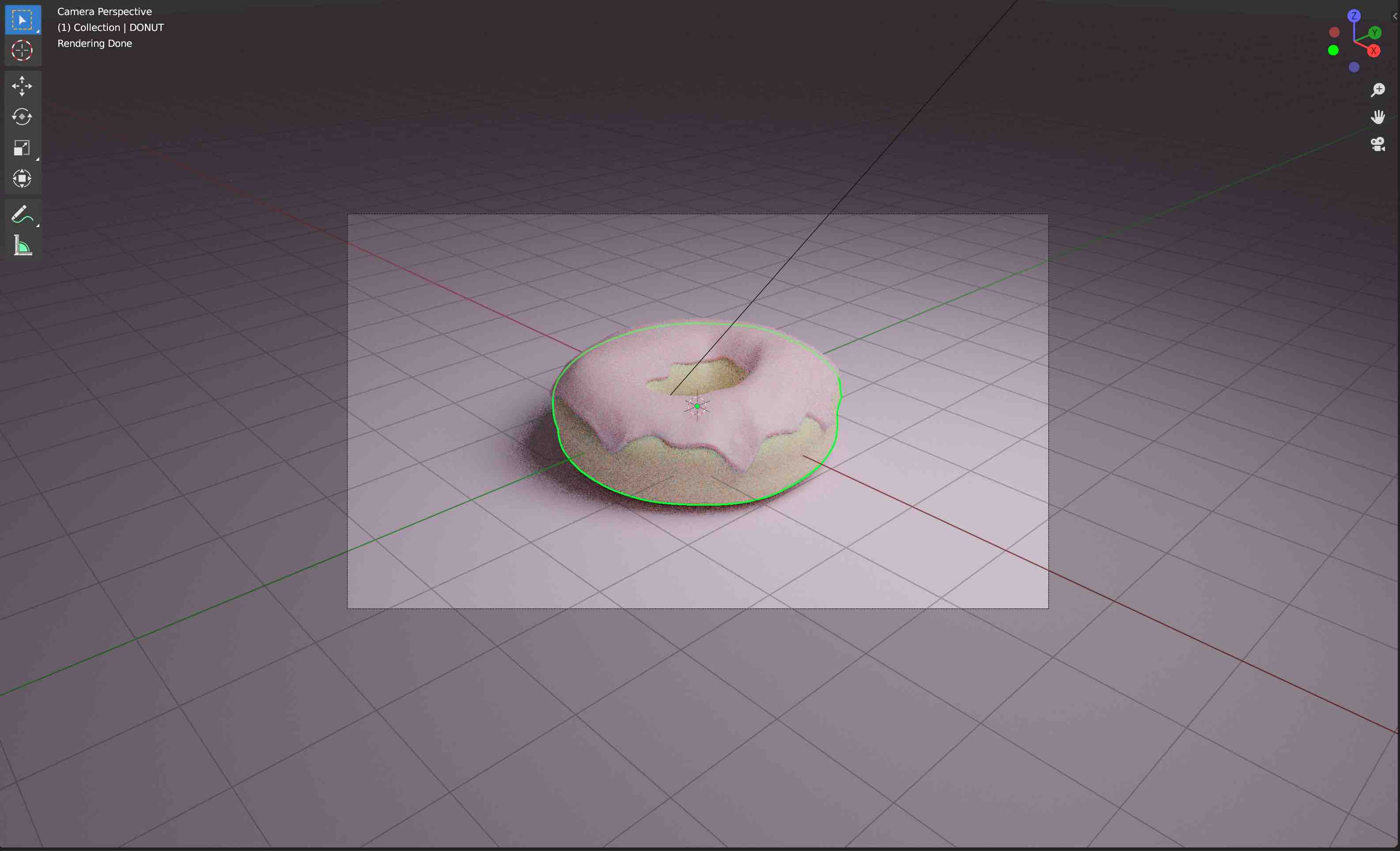
2. Blender
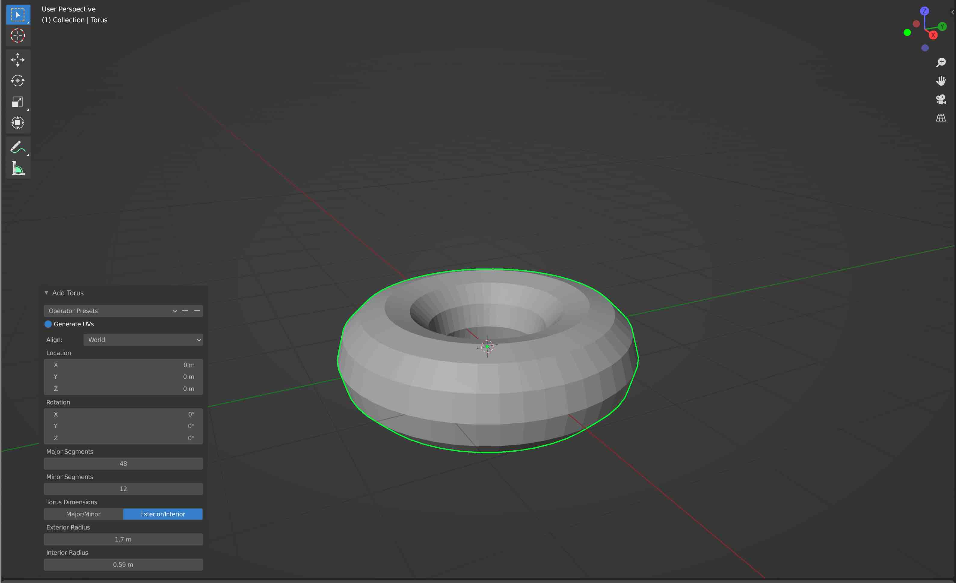
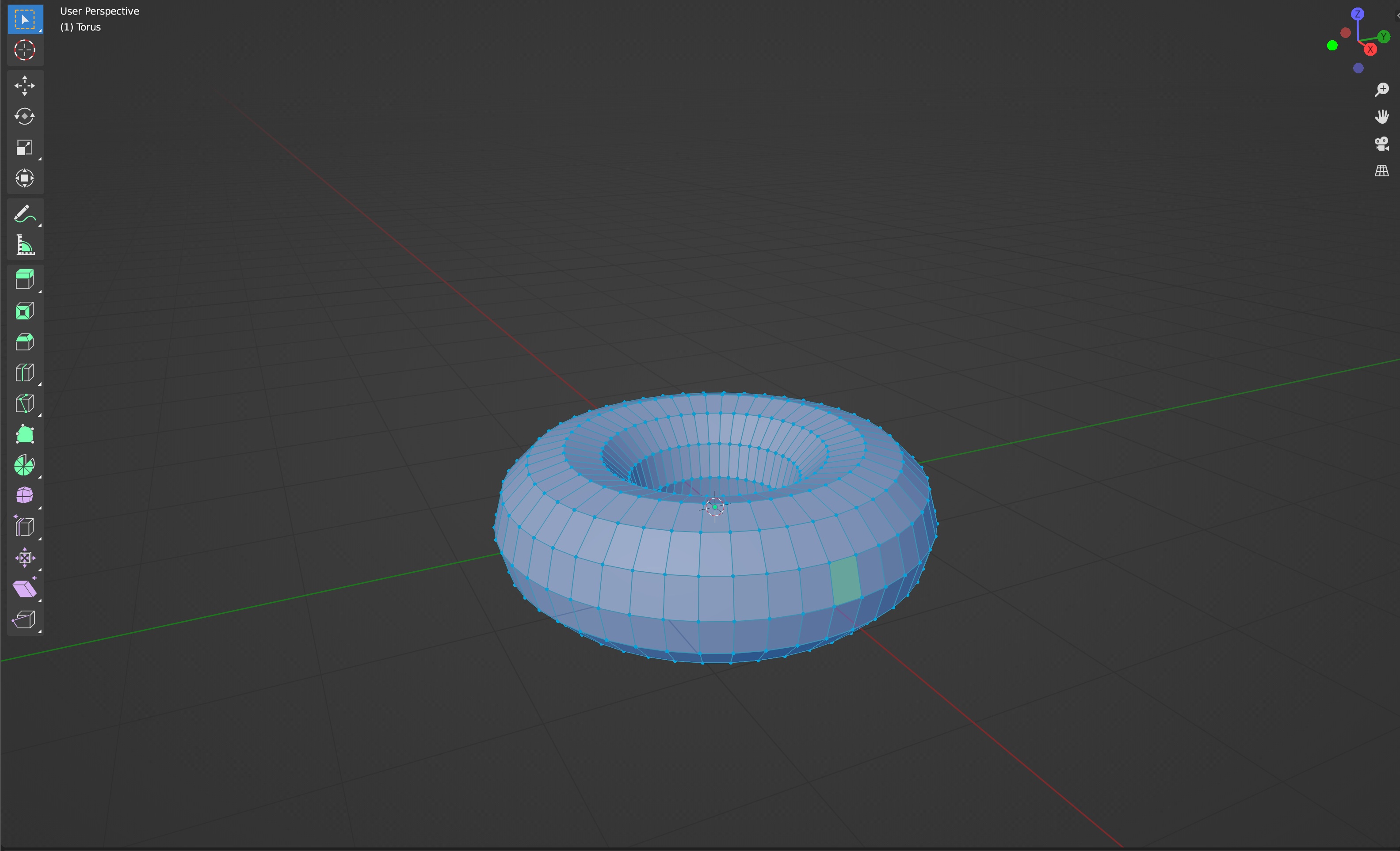
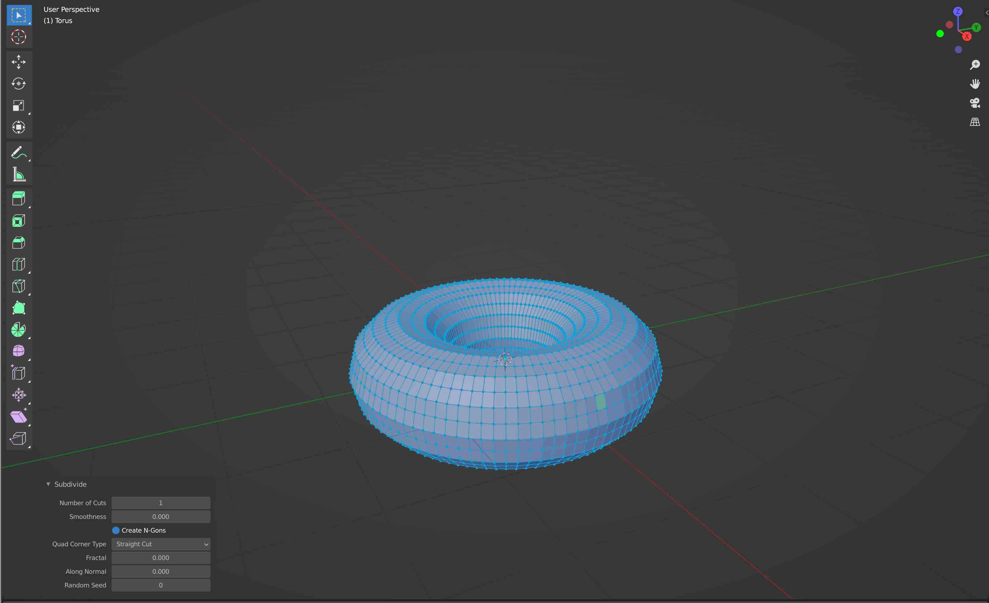
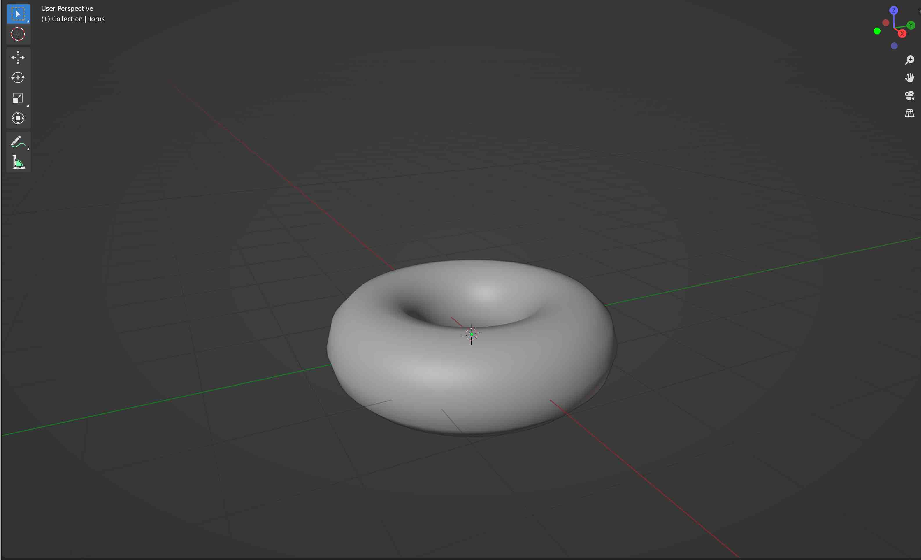
To familiarise myself with the interface and tools, I followed a tutorial provided by Blender Guru on youtube. The tutorial centred around modelling a donut, modifying its mesh to create a realistic surface, and rendering the completed object.
3. Summary
The 3D CAD softwares I have used this week are noticably different as they were both designed for different purposes. I believe that Fusion360 is easy to learn and use. However, it’s framework is too rigid for my taste as it feels less intuitive than other 3D modelling softwares I have used in the past, namely Rhhinoceros. On the other hand, Blender is much more flexible tool which offers a wide array of model shaping tools but also rendering and animation featurs. While it is essential to work with a MESH to appreciate the full breadth of its capabilities, the high number of features makes it rather intimidating to use, even for simple modelling tasks.
B. 2D
I then moved to 2D CAD to compare vector based images with raster based images. I commonly use both Photoshop and Illustrator, so I decided to try Inkscape and Krita. Both are well known free vector and raster based softwares, respectively, and I had never used them in the past.
1. Interfaces
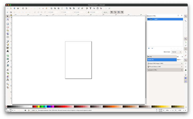
Inkscape
Inkscape’s interface is quite clean and simple. Everything is laid out around the canvas. The tools which allow for the addition and removal of elements to the canvas can be found on the left. Editing tools for the workspace and objects can be found at the top. Tools used to edit one or multiple objects are displayed on the right. Finally, a color palette at the bottom of the screen allows for quick color adjustments. All tools can be placed at different locations by clicking on them and dragging them to the desired location.
Krita
Krita’s interface feels very similar to Photoshop. The default workspace is organised in the same manner as inkscape’s. However, It can be modified by selecting predefined templates in window/workspace, or by adding specific tool docks, known as dockers, by heading to settings/dockers. These can then be dragged to a desired position to create a custom workspace.

2. Comparison
Using Inkscape, I first placed random colored shapes on an A4 canvas. I exported the file as an SVG, and opened it on Krita.
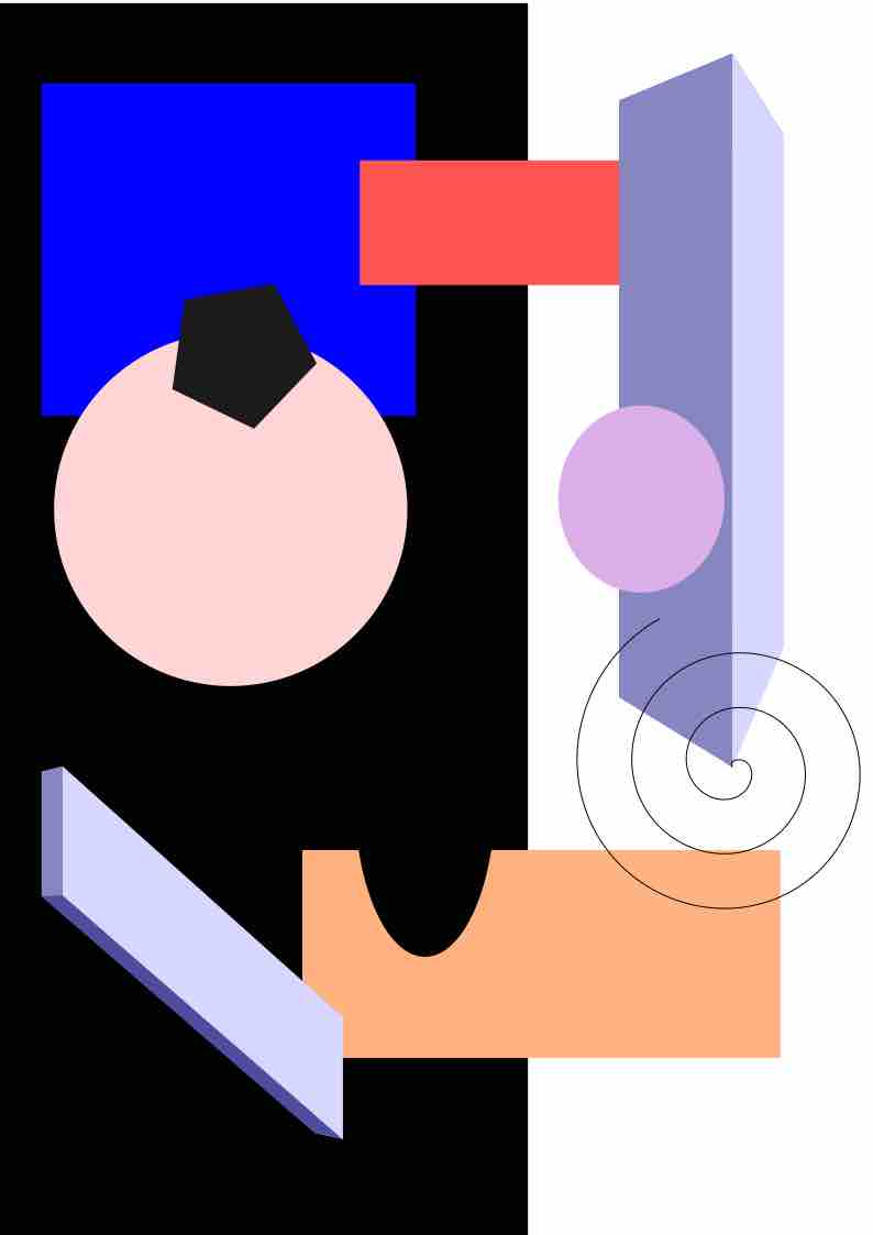
In both Krita and Inkscape, I zoomed in on specific features to observe how detailed they would be. The difference was quite striking. Even though Krita can read SVG files, it natively converts them to raster images. As such, pixels defining the image become visible once I zoom in. If I increase the number of Pixels per inch (PPI), I must zoom deeper to start seeing the pixels. The below images depict this.


3. Summary
The use of vectors to define the characteristics of an image allows for them to be scaled infinitely. On the other hand, raster based definitions do not as a finite number of pixels are assigned a specific color. this makes the latter much more adapted for a deep manipulation of colors at the expense of a loss of definition compared to vector based operations. I am eager to see how this will affect our use of these types of softwares throughout the course.
In terms of software performance, the MacOs version of inkscape is slow and unresponsive at times making it Difficult to use. I don’t believe I’ll be switching for the duration of the course. Krita on the other hand is quite good. I’ll keep exploring it when I have the chance.
C. Files
Z. Appendix
1. Lecture Notes
Basic CAD Concepts
Basic 2D Concepts
a. Processing and Foundations
Vector Images
Geometric/mathematical description of an image. Lines, shapes and other graphic components described by geometric formulas define the image.
- [+] Allows for enlargement without loss of quality.
- [+] Easy to manipulate and modify
- [+] Small file size
- [-] Requires a greater amount of Processing.
- [-] Does not store textures. Difficult to blend colors.
- [=] Best for digital illustrations, logos [..].
Raster/Pixel Images
Smallest unit of BITMAP images, a.k.a: Raster images or BITMAPS. Array of bits with a rectangular grid describing pixels.
- [+] Stores Textures. Capable of rich, complex color blends.
- [+] Image processing is less demanding than vector images.
- [-] Image enlargement leads to loss of information. Constrained by resolution and dimensions.
- [-] Texture storing requires large volume of RAM.
- [-] Heavier than vectors as the value of each pixel needs to be registered. But offers a variety of formats and compression.
- [=] Best for photos.
Image Resolution
Number of pixels in an image. Generally Expressed as: - NumberinWidth x NumberinHeight for screens. - Product of width and height in pixels for cameras and pictures.
PPI
Pixels per Inch. Measure of pixel density. - 320PPI is the average density observable by the human eye at a distance of 10cm.
Recommended formats:
- Internet: 72-150PPI
- Print Jobs 150-300
b. Color Space Profiles
RGB
Additive color model based on the colors Red, Green and Blue. Colors are formed by adding hues to another. Used in displays.
CMYK
Subtractive color model composed of Cyan, Magenta, Yellow and Key(Black). colors are formed by deducting hues from another. Used for printing.
standard RGB - sRGB
Developed by HP & Microsoft in 1996 with the purpose of creating a consistent color system.
- [+] Consistent. Online representation will most likely be the same on all platforms/devices.
- [-] Cover 35% of the Human visual spectrum. Color range and luminance are limited.
Adobe RGB
Developed by Adobe. Offers access to a greater color range and is therefore suitable for high quality photographs and image editing.
c. Image Formats
.PSD/AI
Propietary formats for Adobe Photoshop (Raster) and Illustrator (Vector).
Raster
.RAW-NEFF
Processed directly from the camera’s sensor, thus they do not use compression. Also obtained from scanners.
- [+] Lossless, the images are extremely high-quality.
- [+] Show more shades of colors and better representation of white balance, contrast, exposure  etc.
- [+] Changes made to RAW files are non-destructive. Only the metadata that controls the rendering is altered, but the original file data remains untouched.
- [-] Additional information means files are extremely heavy.
.JPEG/JPG
Joint Photographic Experts Group
Most common file type which can be used online or for hard prints. Lossy compression algorithm removes minute details that your eye is least likely to notice to save space.
- [+] Adjustable compression ratio.
- [-] Layers are flattened. Can't tweak past edits.
- [-] Several edits of a file may lead to a loss of quality.
.PNG
Portable Network Graphics
Popular format used by photographers and graphic designers.
- [+] Supports lossless data compression.
- [+] Can be shared on the WEB.
- [+] Transparency options. Maintains 3D quality.
- [-] Larger file size than JPEG
.TIFF
Tagged Image File Format.
The information is retained in layers. The information is retained in layers
- [+] Lossless & High quality.
- [-] Extremely Large.
- [-] Can't be displayed on the internet.
.SVD
Singular Value Decompression.
Vector imaging compression format.
d. Compression
Lossy Compressed - Loss of information viewed as not noticable. a.k.a irreversible compression
Lossless compression - reduced loss of information or no loss of information
RAW - Original file
Basic 3D Concepts
a. Methods
Sketch-Based Modelling
- 2D shapes are converted to 3D to create models.
Freeform Surface Modelling
- Editable surfaces makeup 3D models.
Parametric Design Modelling
- Geometric drawing defined by a set of rules.
b. Model Structures
MESH
-
Saves location of points (vertices) in space and registers the proper connections (faces) effectively creating a mesh of polygons.
-
RAM/GPU Consuming.
- Conversion to NURBs is complex
NURBs
-
Saves a Mathematical representation of 3D objects.
-
Easier to manipulate and modify.
- Can be converted to MESH
=== “3. File Formats”