3. Computer Controlled Cutting
This week focused on computer controlled cutting. We were introduced to various laser (Trotec 100/400) and vinyl cutters through hands-on group exercises.
A. Group Assignment
-
Characterize your lasercutter’s focus, power, speed, rate, kerf, joint clearance and types
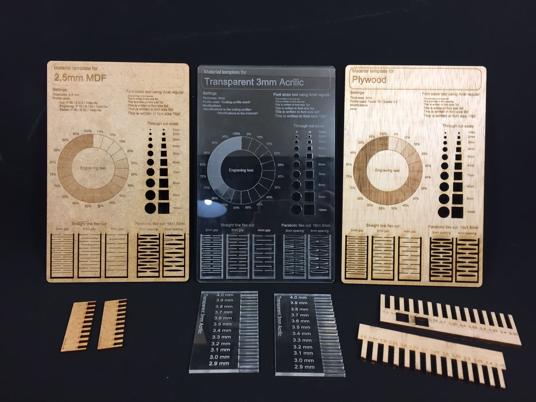
Kerf, engraving and living joint tests for MDF, Acrilic and plywood
Focus - Establishing the correct distance between the laser’s lens and the material being cut/engraved.
Power - Defines the intensity of the beam produced by the laser.
speed - Defines the speed at which the laser unit moves during the cutting process.
Frequency - Defines the rate at which the laser is switched on and off during a cut operation. (expressed in Hz).
Power, Frequency and Speed are set manually on the Trotec software before launching an operation.
Kerf and Joint Clearance
Tight fit can be achieved with a 0.2 mm increase/decrease in joint thickness for male/female elements respectively, giving a joint clearance of 3.8 mm for 4 mm thick plywood.
B. Individual Assignment
- Cut something on a vinyl cutter
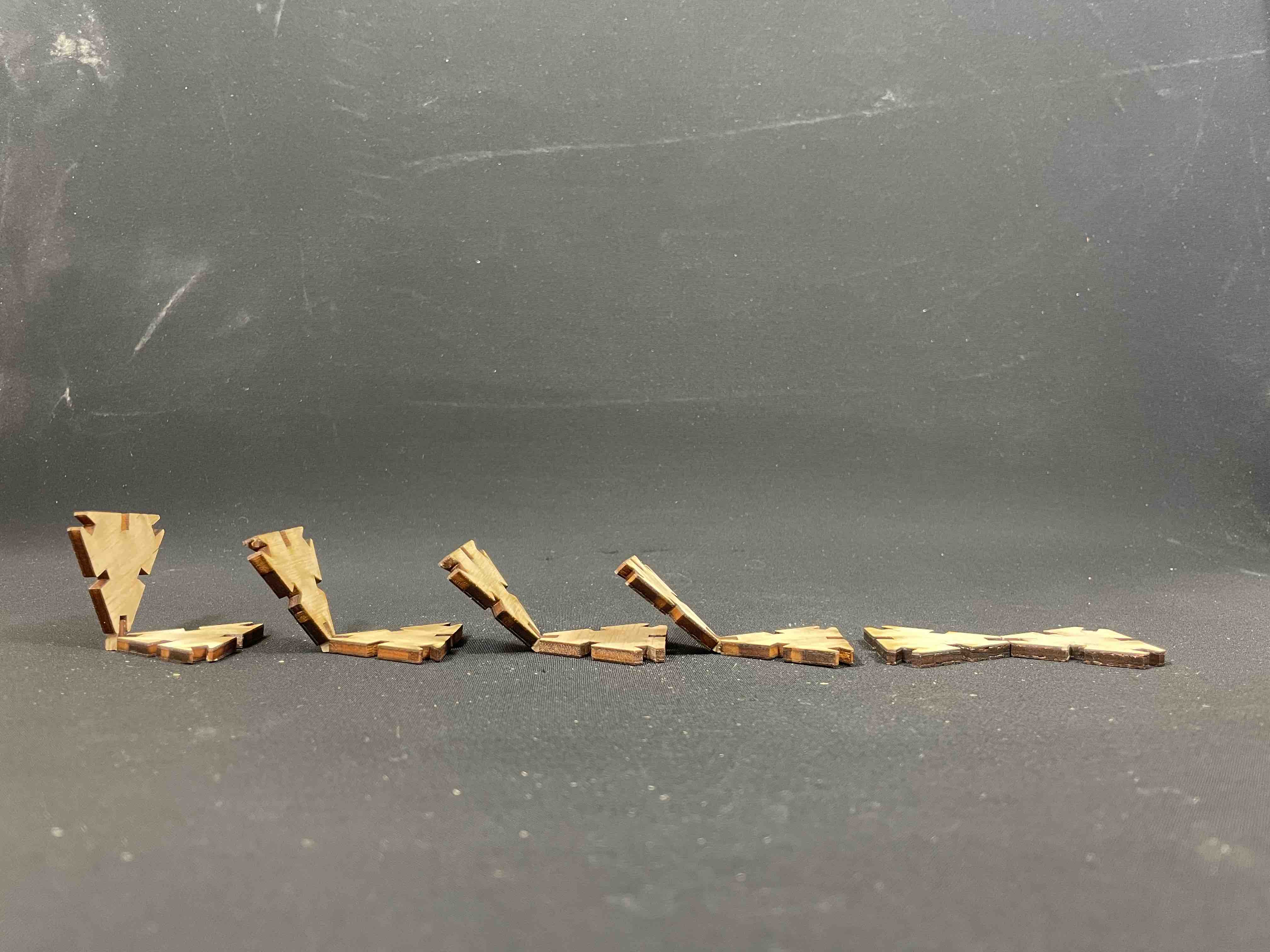
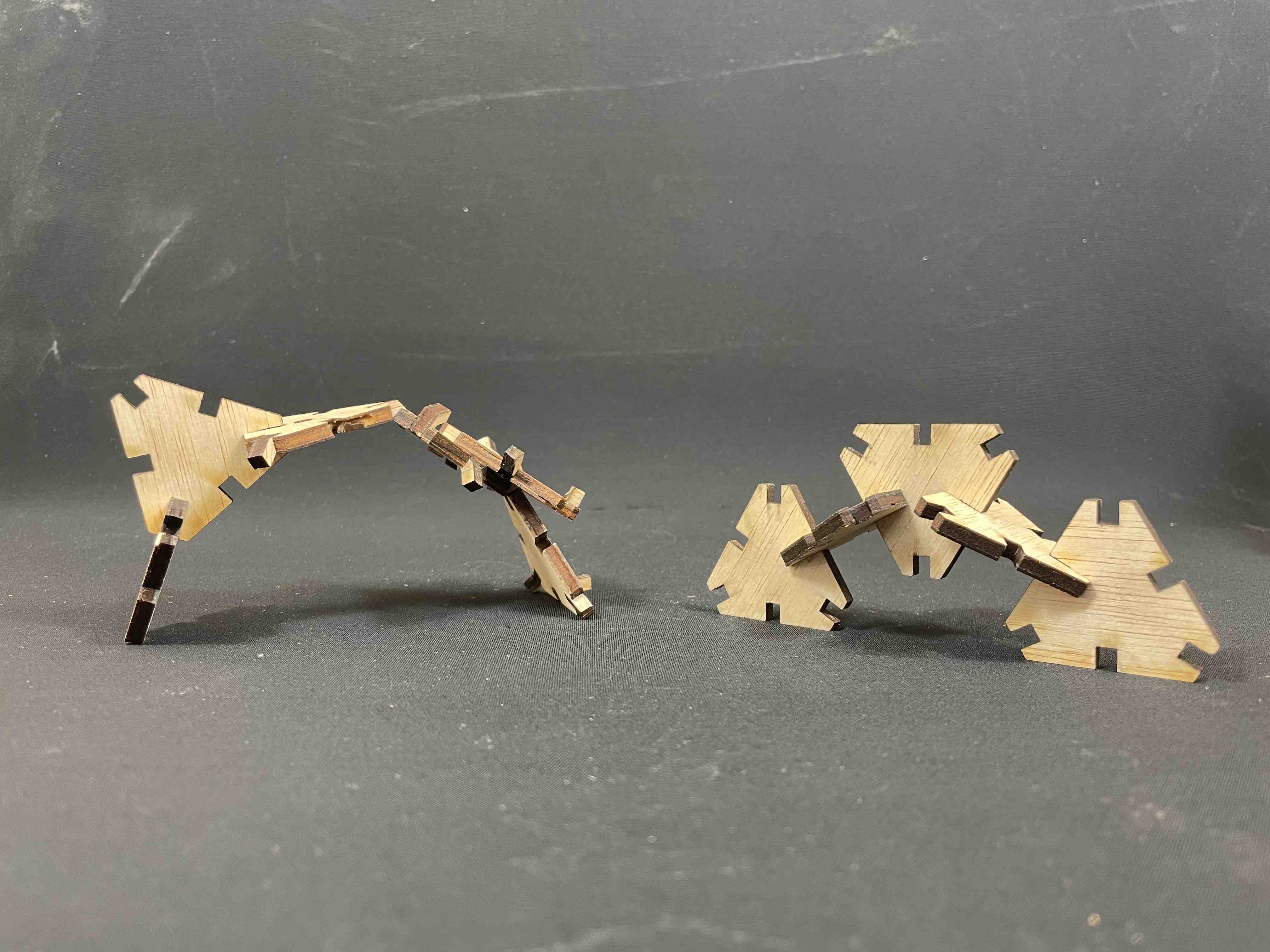
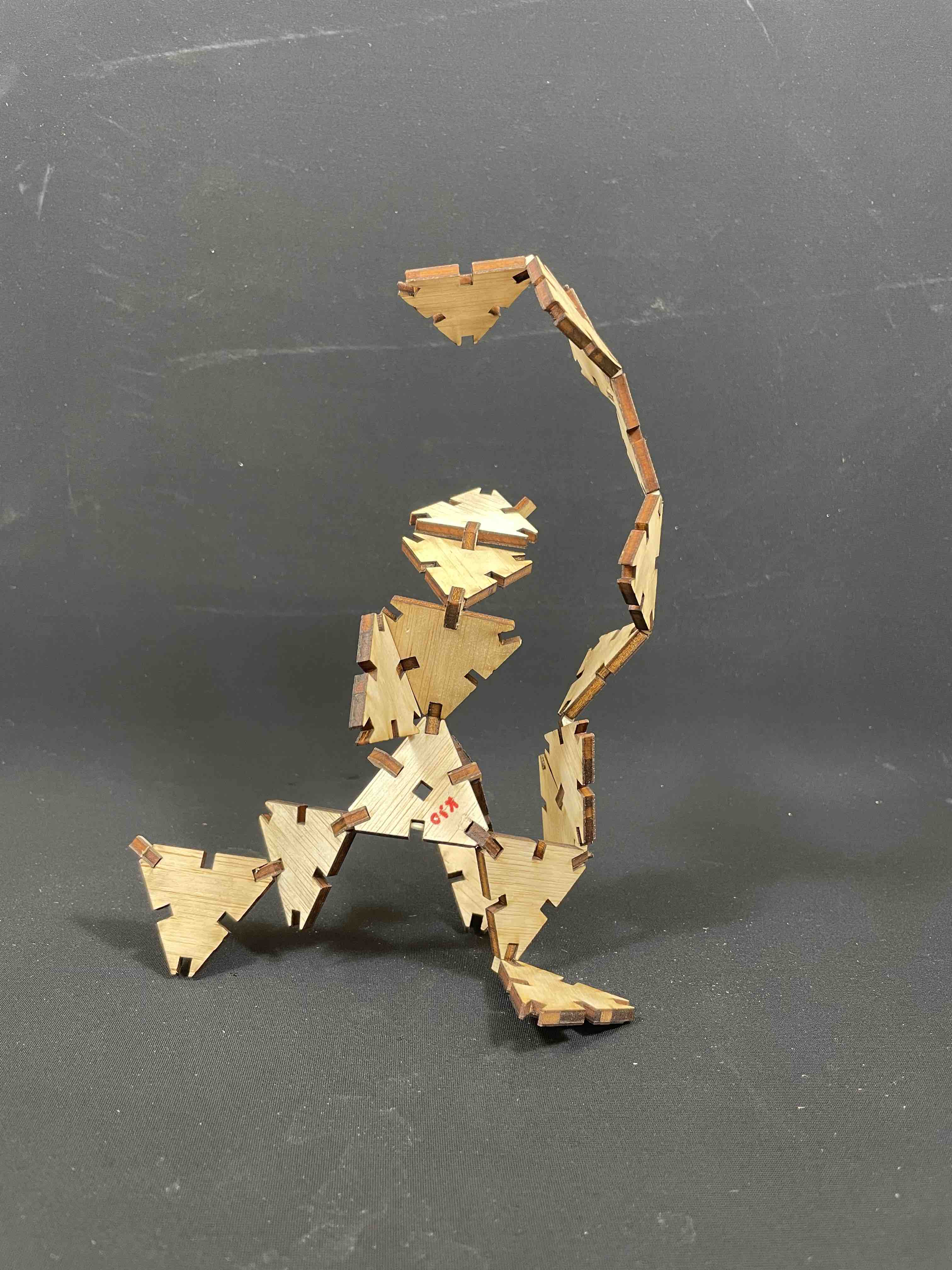
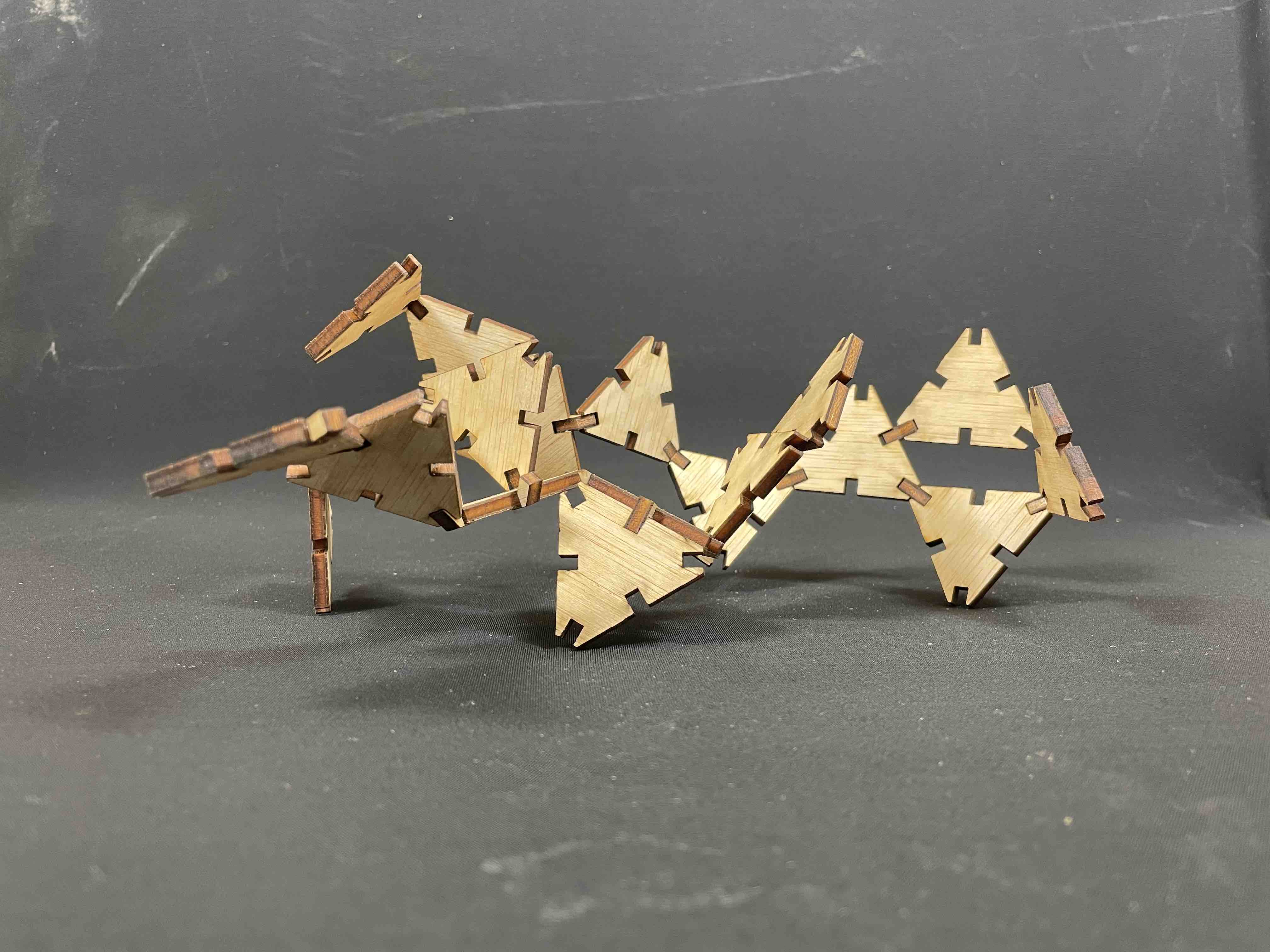
- Design and lasercut a parametric construction kit which can be assembled in different ways.
I. Laser Cutter - Parametric Construction Kit
1. Modelling in Grasshopper
One of my primary motivations for applying to the FabAcademy program at the Barcelona Fab Lab was to benefit from the university’s renown in parametric design to gain exposure to the subject. The computer controlled cutting courses introduced many parametric CAD tools such as sCAD and Rhino’s Grasshopper extension. I chose to work with Grasshopper as I was keen on learning to use its visual programming environment.
My initial idea was to design a kit that could be assembled into any basic geometrical volume (Cube, Sphere, Cylinder etc.). I took took inspiration from the structure of Free form surfaces in CAD, more specifically, the MESH of triangles that compose them. I therefore looked to create a kit centred around the use of triangular cuts.
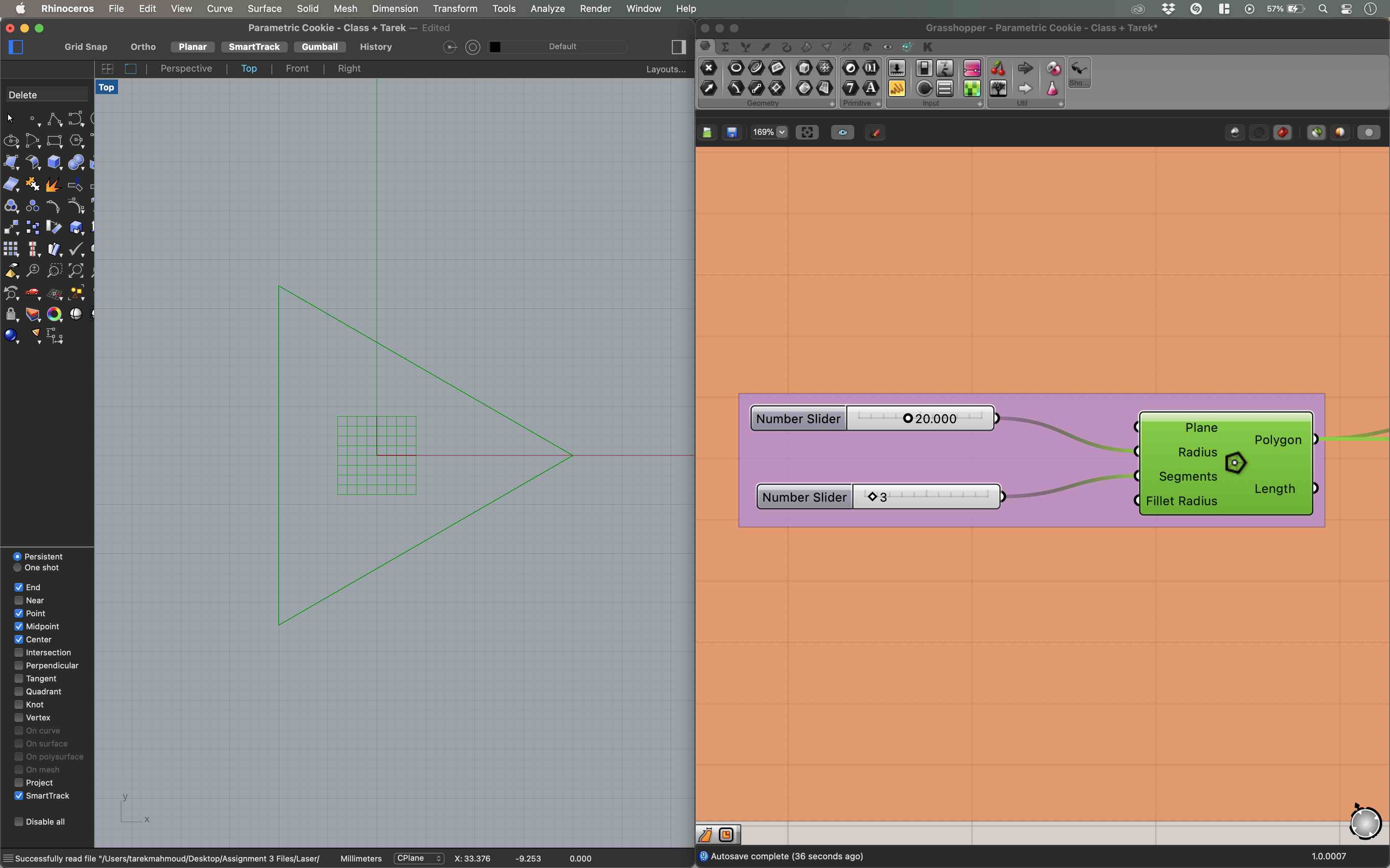
Creating a triangle in grasshopper was relatively straight forward. I initiated a polygon and set its number of segments to 3. I then added a couple of functions to create slots at each vertex and the midpoint of each segment.
I then looked to replace the triangle’s vertices with segments for no particular reason. This proved to be intricate as I needed to find a way to isolate specific vertices and segments to create elements I could freely manipulate. I worked with functions built around Lists which allowed me to decompose curves and segments into lists of segments and points.
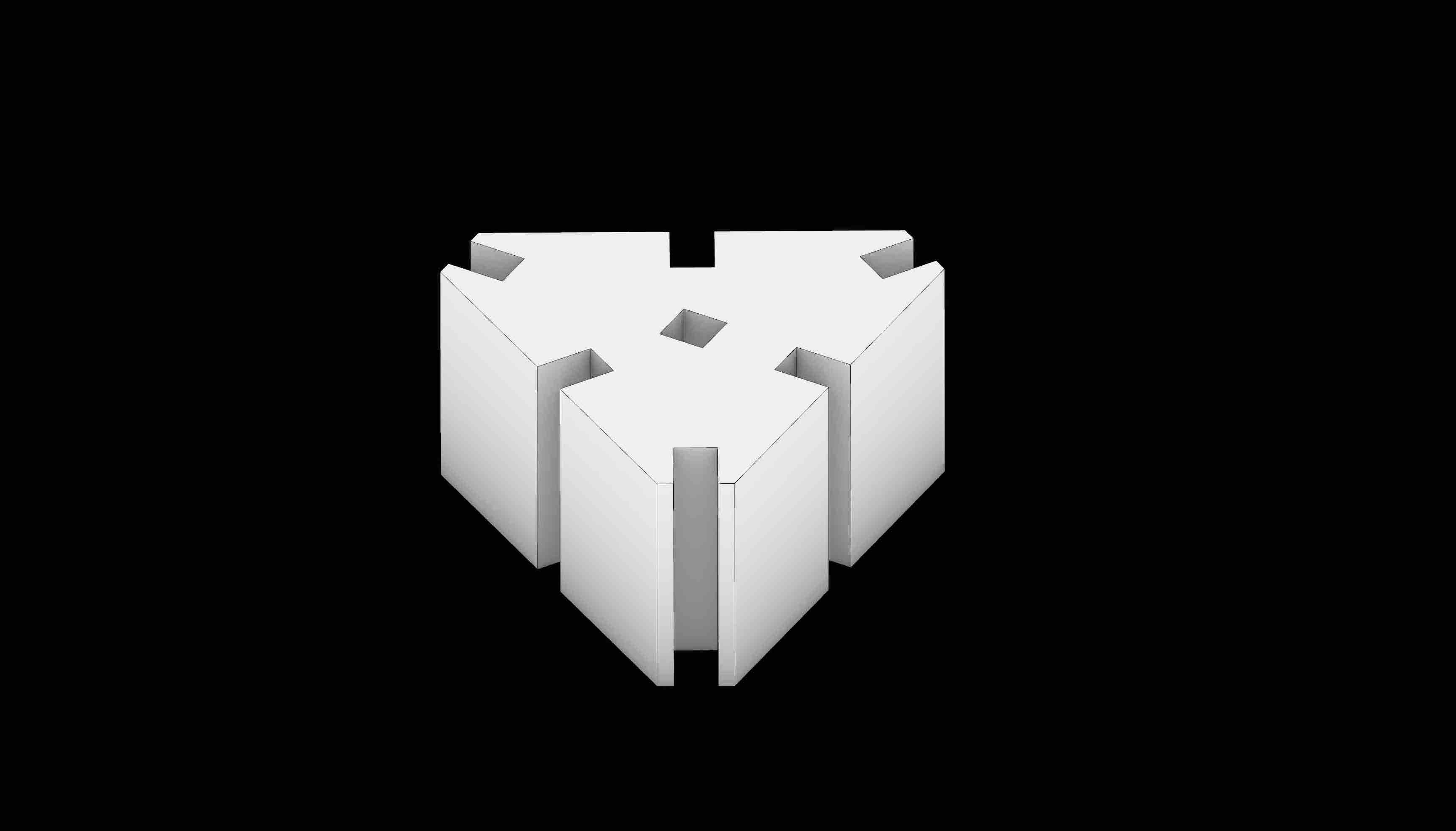
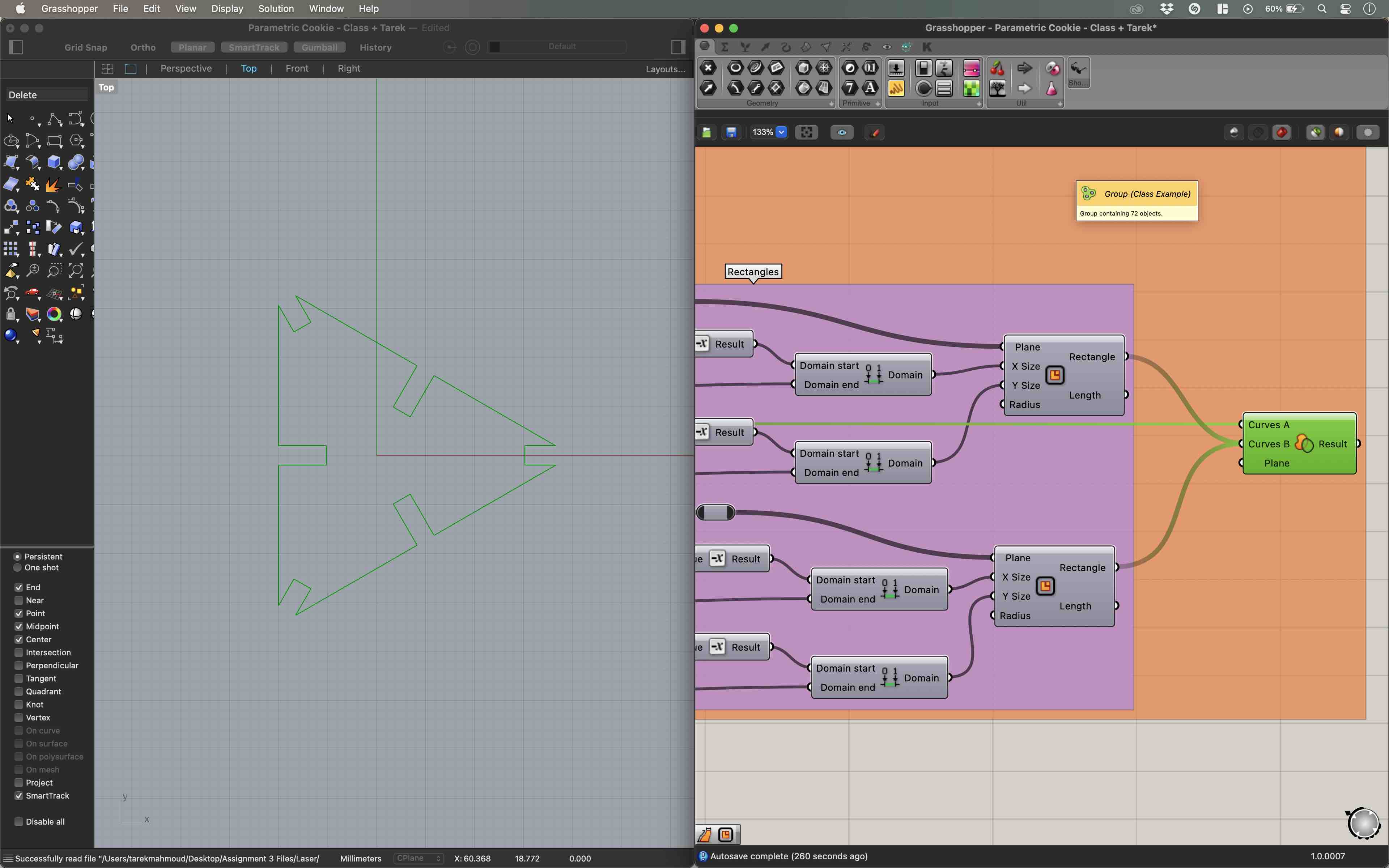
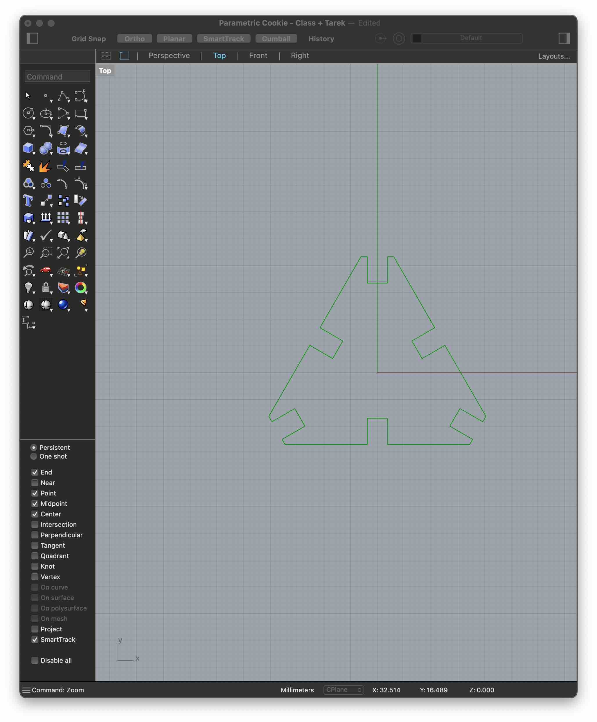
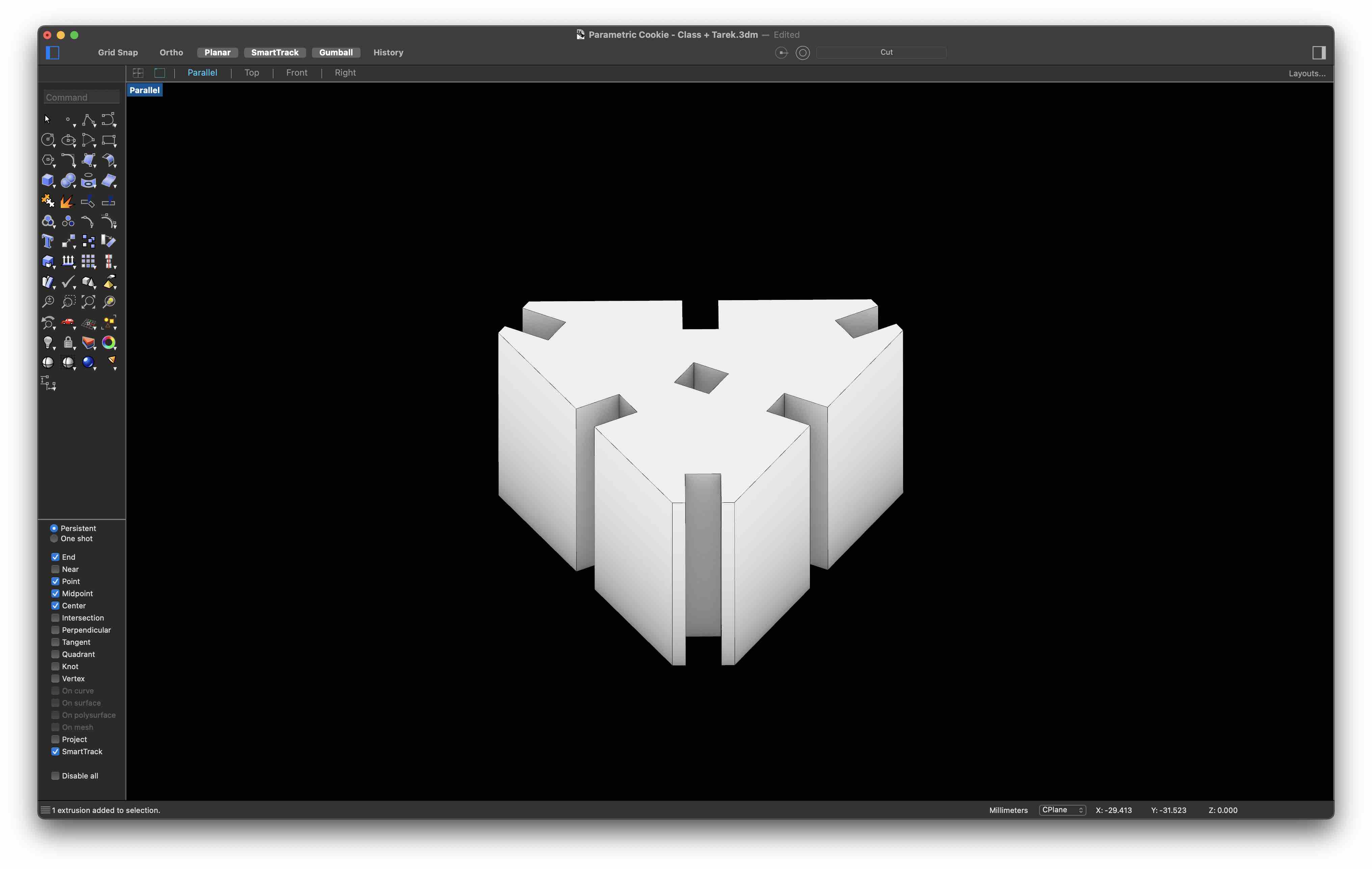
The visual program I created reduces the dimensions of three faces of a Hexagon to create the desired shape. It allows for the factor of this reduction to be modified manually with the shape adapting to the values set. The same can be done with the radius of the polygon, depth and thickness of the cutouts as well as the lasercutter’s kerf. Furthermore, the number of segments can also be modified if desired as demonstrated below all of this.
The shape I went for can be seen in the below Rhino screenshot.
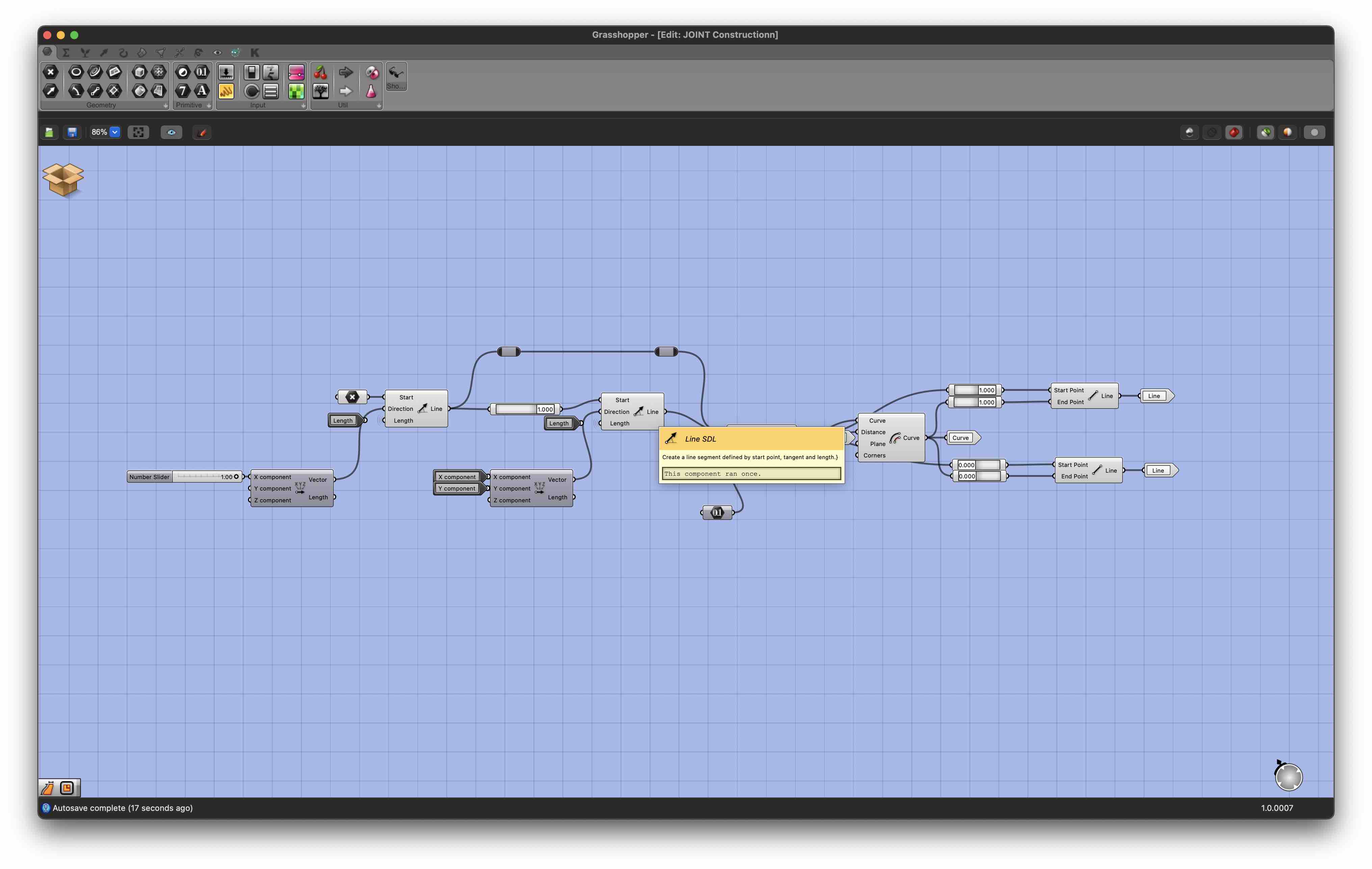
The developed grasshopper file is too long to show or explain in detail here but can be downloaded a the bottom of this page, along with all other files created for this week’s assignment.
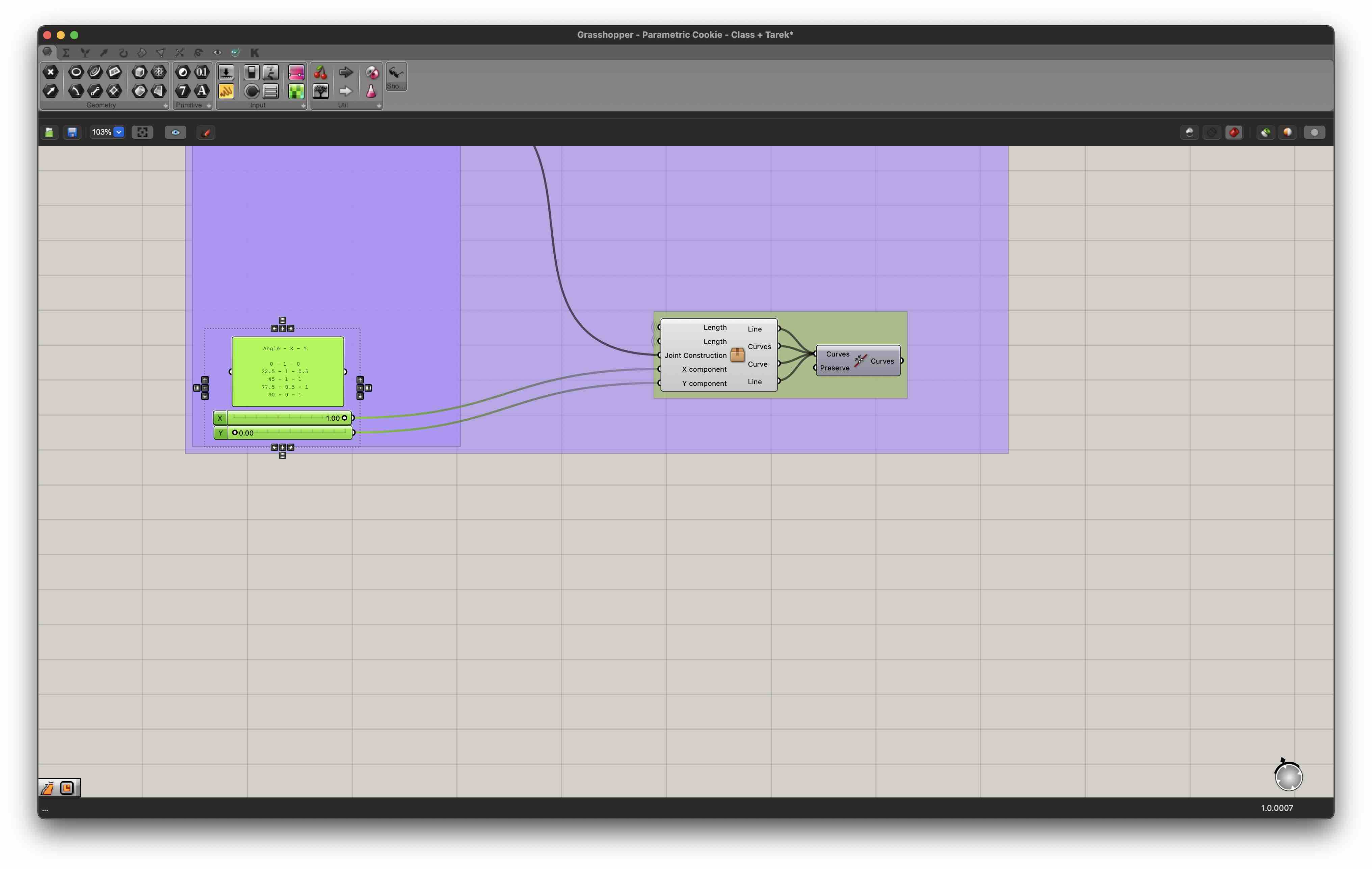
I also designed elements that would allow triangular cuts to be joined at varying angles. These are simply two rectangles that form an angle equal to 180, 157.5, 145, 112.5 or 90 degrees and are slotted in the cutouts.

Similarly to the triangular shape, I developed a grasshopper flow that enabled me to modify the angle by changing a couple of parameters.
2. Cutting on the Trotec
All elements were cut from 4mm thick plywood. The settings used for cutting and engraving were the following:
| Operation | Power | Speed | Frequency |
|---|---|---|---|
| Cut | 75 | 0.5 | 1000Hz |
| Engrave | 65 | 0.5 | 1000Hz |
In order to prevent any possible accidents that might lead to the damaging of the machine and its environment, people being harmed, or improper cuts, I had to respect a set of “golden” safety rules listed below:
Before launching the cut
Quality Rules
- Material has been laid flat on the machine’s cutting surface.
- If the material has a “belly” (i.e. is bent towards its centre so as to form an arc), place the material so that the apex of the bend touches the cutting surface.
- Ensure the proper Power/Speed/Frequency settings have been selected. These can be found in the lab on a dedicated board.
Safety Rules
- Ventilation has been turned on
- Material is allowed on the cutter
- Laser has been focused
During the cut
Safety Rules
- Keep an eye on the machine and changes in state of the material being cut.
- If the material catches on fire for more than a few seconds, do pause the system pause the operation.
- If the fire does not turn off, stop the operation completely, move the laser beam away from the fire and ask for help.
After the cut
- Once completely done, take the whole material plate out of the machine, along with the cuts.
- Clear the dedicated computer from the files used.
While the Kerf had already been found, I needed to determine the joint clearance of my elements. To do so, I used a ‘kerf scale’ cut from plywood for the group assignment, yielding the following values:
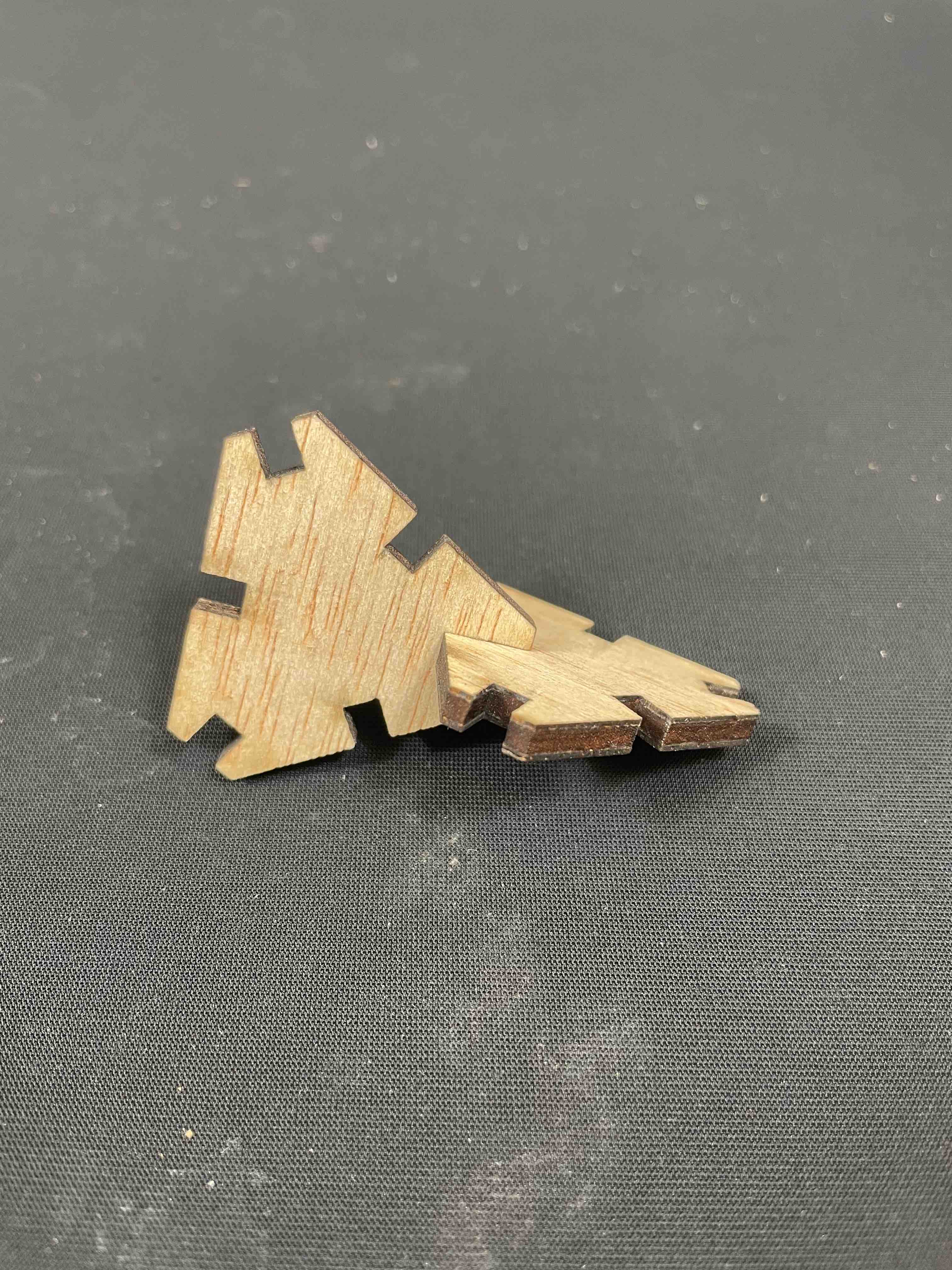
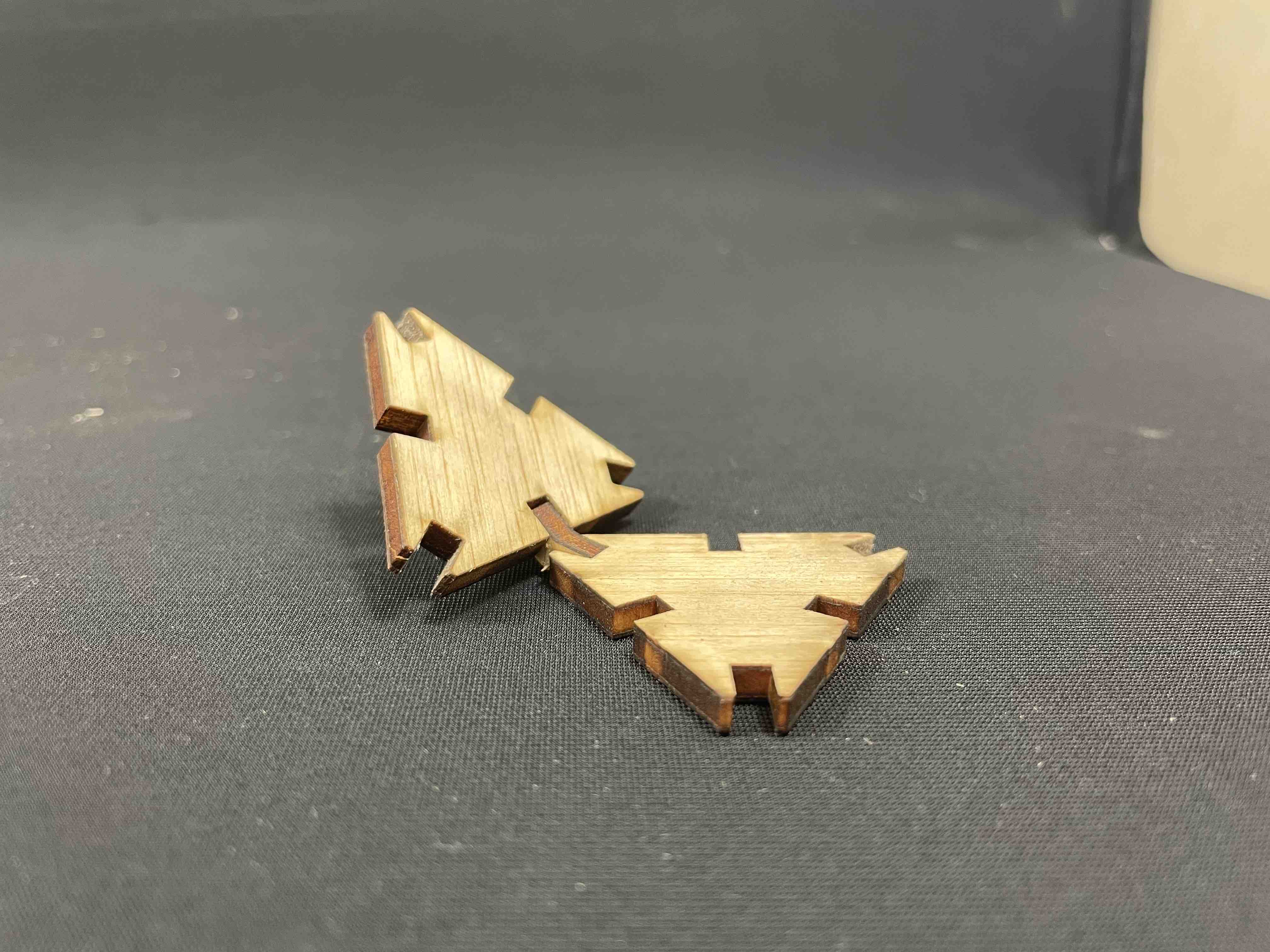
Slot Thickness 3.8mm Joint Thickness 4.2mm
These were found to allow for tight connections between elements.
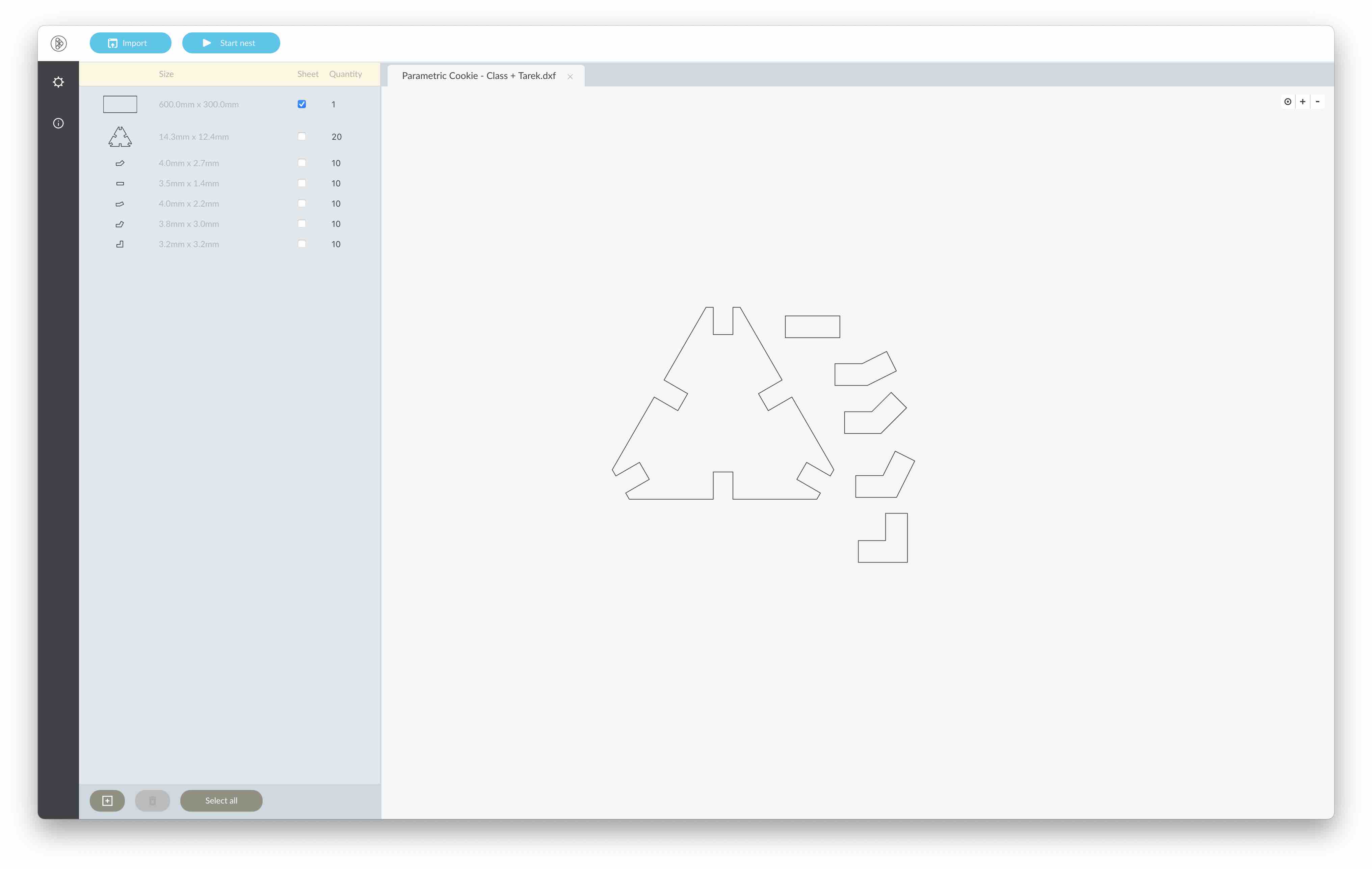
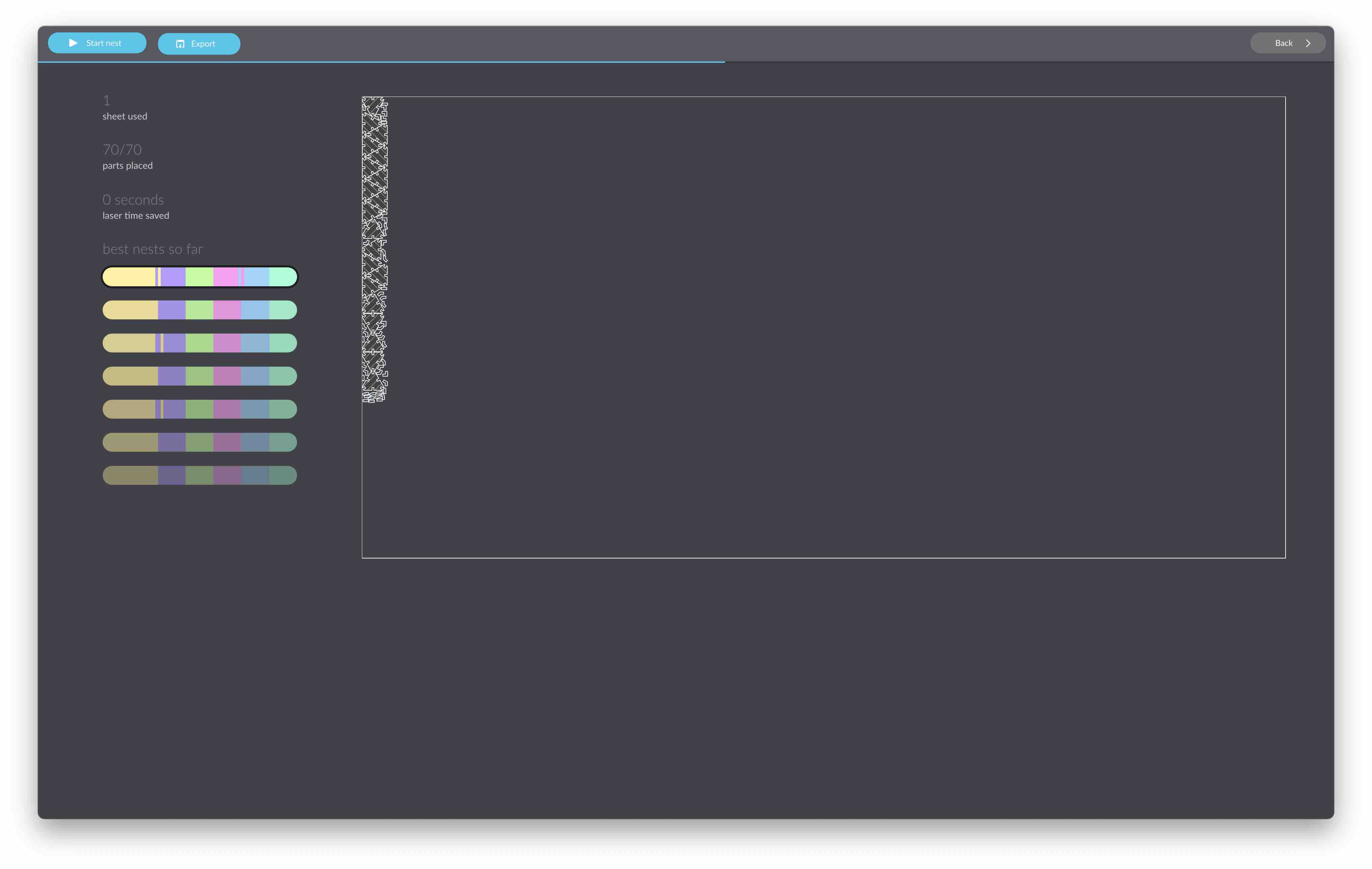
Once All CAD files had been completed, I exported 2D drawings of each elements in .dxf and used deepnest.io to nest these on a 600x300mm plate.
II. Vinyl Cutter - Sticker
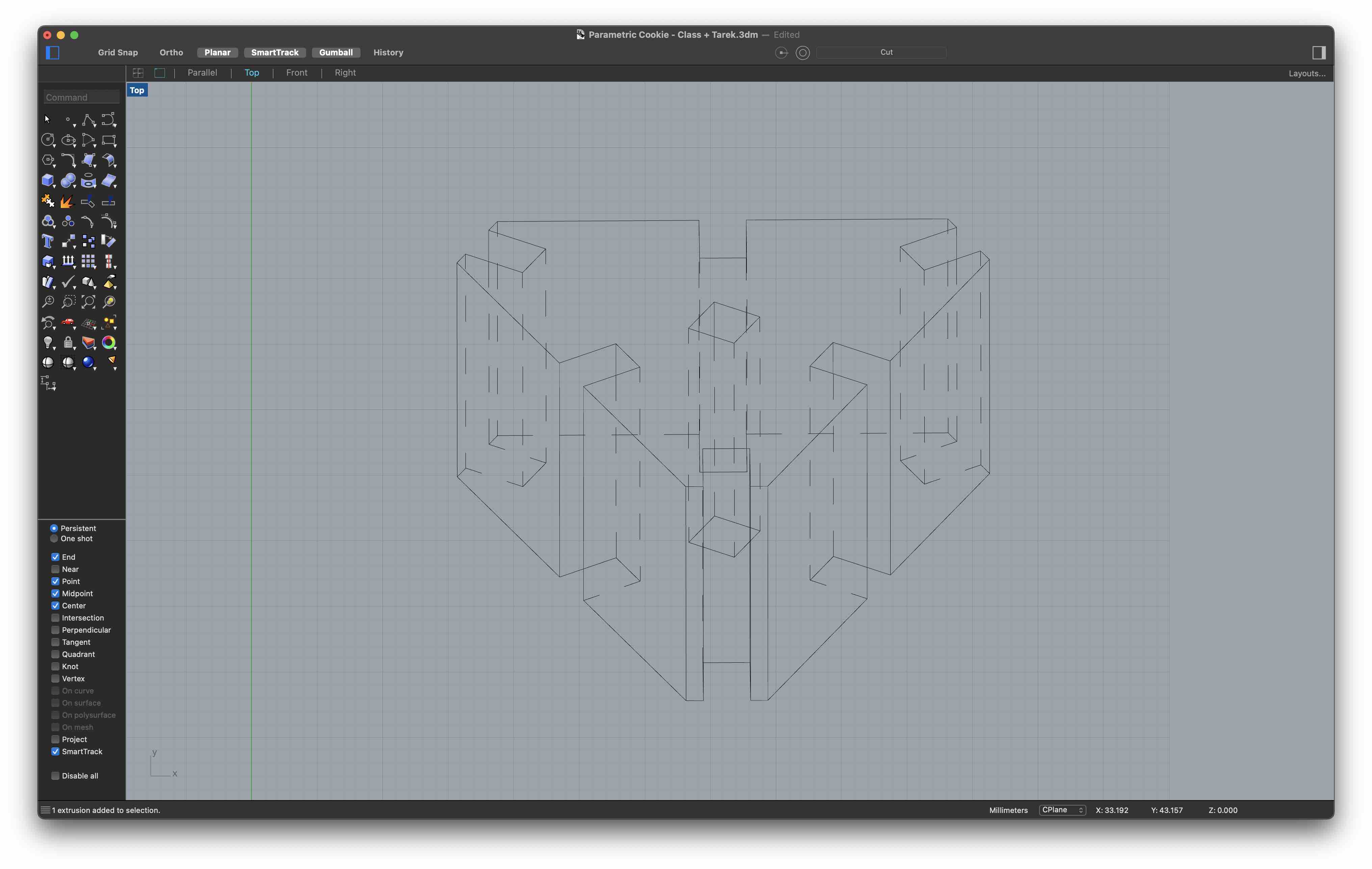
In Rhino, I extruded the triangular element designed for the construction kit. I then oriented the element as follows:
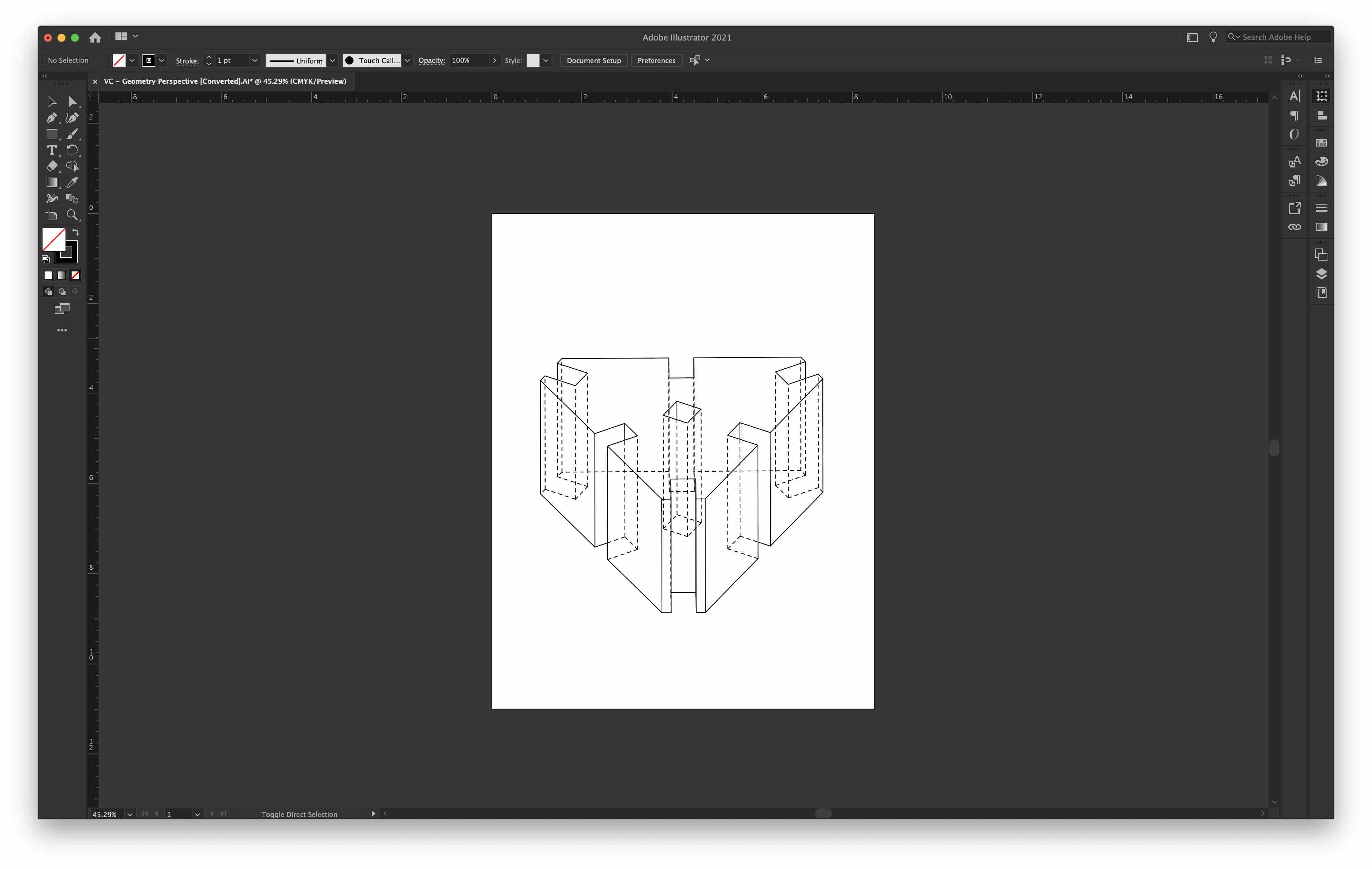
Using the make2D command, I created the following polyline:
I exported the polyline to Illustrator where I edited the lines.
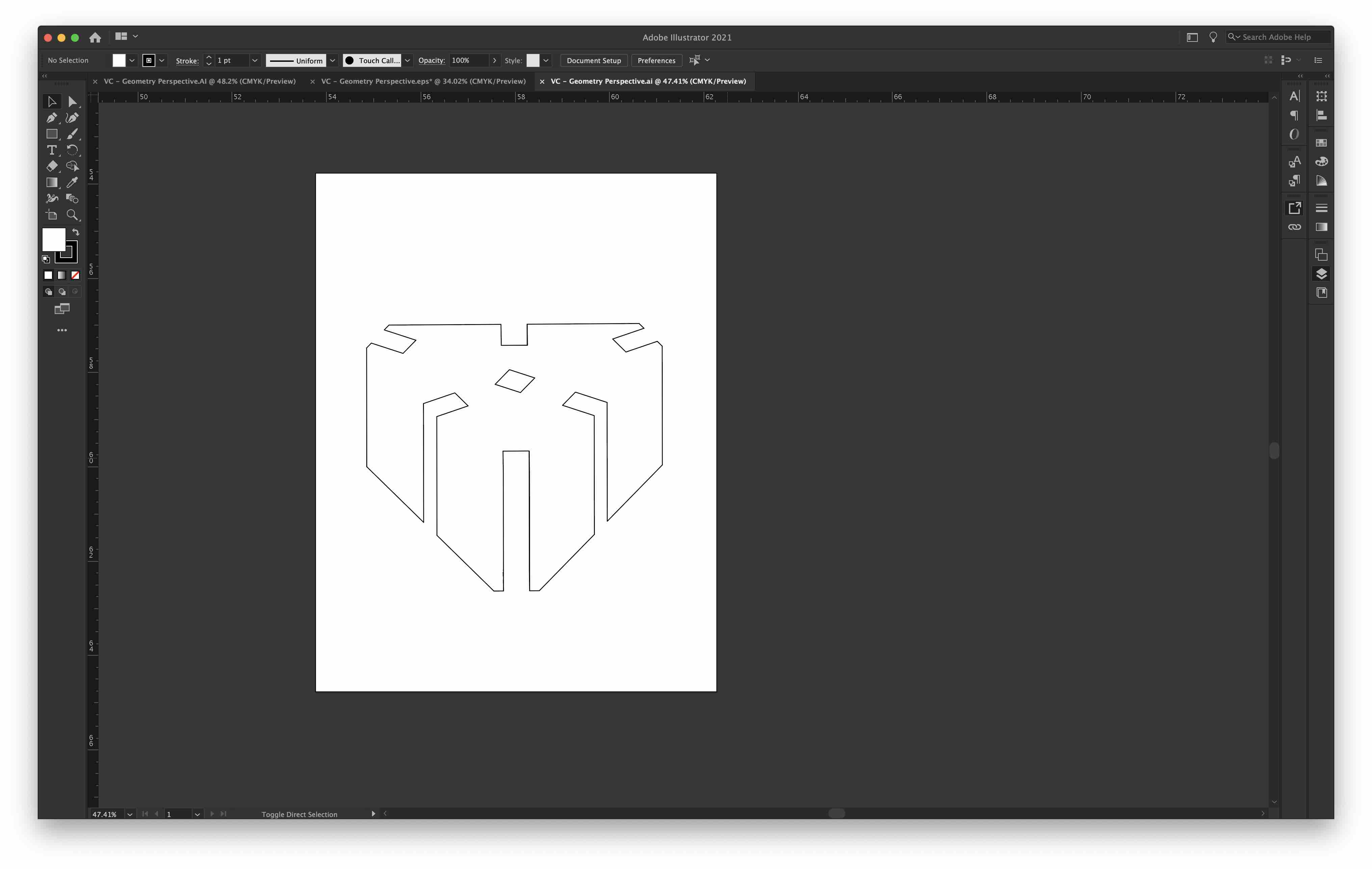
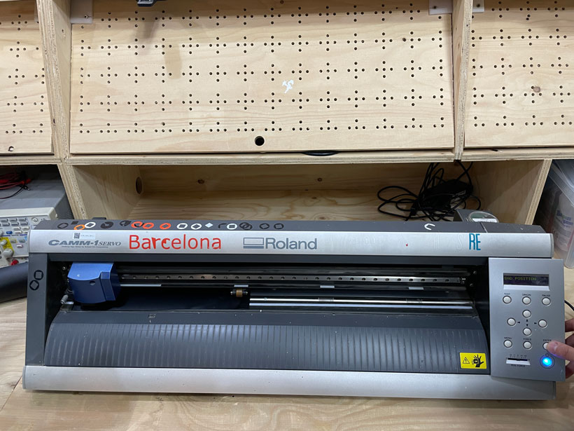
Finally, I cut out the above shape using the Roland GX-24 vinyl cutter available at the Barcelona Lab. For this part of the assignment. I worked with Adrien Laveau and Lynn Dika. We first needed to setup the machine. To do so, we followed the tutorial provided by our Barcelona Fablab.
In summary, we did the following:
-
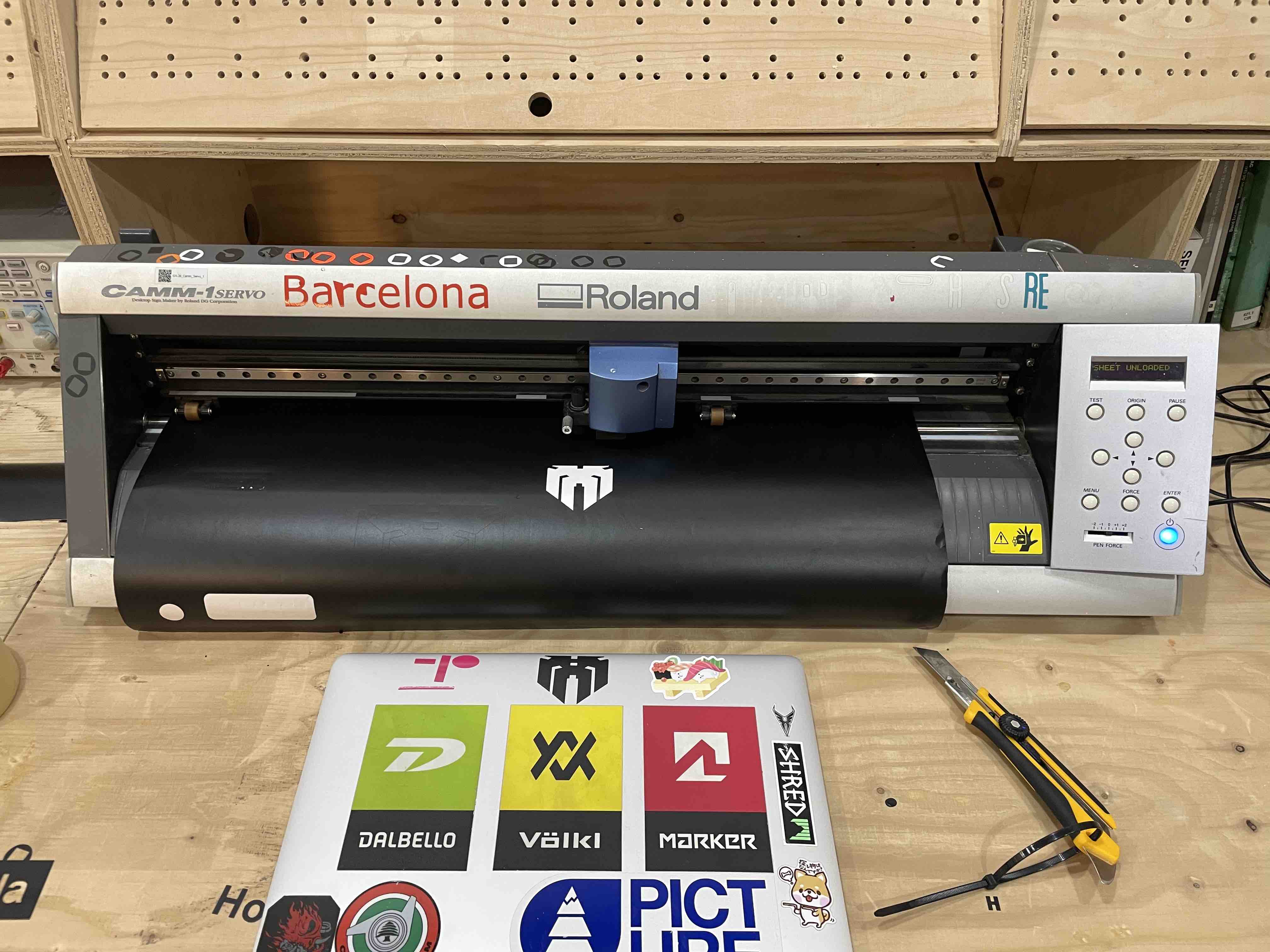
Loaded Material on the cutter by releasing the holding tab from the back.
-
Set the width limit sensor at the correct mark.
-
On the GX24’s interface, set the correct material feed type by clicking. In our case, it was a piece. The other option was roll.
-
Waited for the machine to measure the length of the material.
-
Installed and calibrated the cutting tool.
-
Set the desired cutting speed.
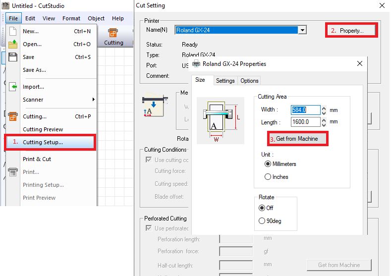
We used CutStudio, a Roland Proprietary softwafre, to send files to the cutter. This also requried for some parameters to be setup before launching cuts.
-
First, set the correct dimensions of the piece of material by heading to File/Cutting Setup/Property/ and clicking on Get from Machine or entering them manually. This sets the canvas dimensions to the material’s dimensions.
-
Import SVG or Legacy Adobe Illustrator files and place them at the desired location on the canvas.
-
Launch Cut
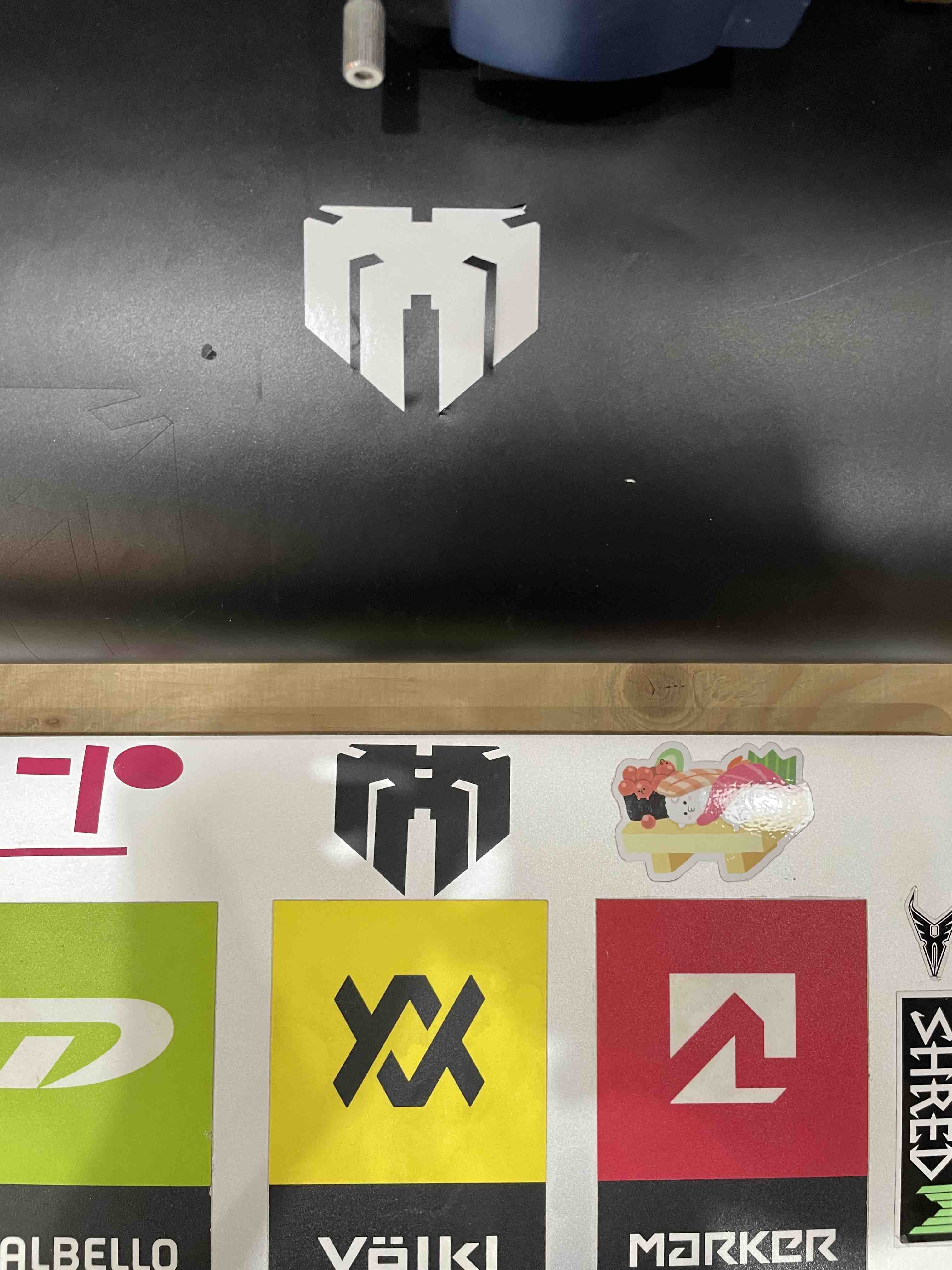
Here’s my vinyl cut sticker on its new home.
C. Summary
What I learned
- How to operate a laser cutter and a vinyl cutter
Notes on Laser cutting
Pros - Great for rapid production. - Even though all cuts are two dimensional 3 Dimensional shapes can be created by stacking cuts, joining them through press-fitting or in waffle structures. - Prototypes can be produced in a very short time.
Cons - Limited choice of compatible materials. - Complex shapes might be hard or even impossible to assemble. - Limited to surfaces at a right angle. - Things can go wrong if the proper steps and security measures are not respected. (Not necessarily a con, but something to keep in mind)
Notes on Vinyl Cutting
Pros - Rapid and efficient. - Precise (for the tasks carried out). - Easy to use
Con - None that I could find from what was done this week.
D. Files
Week 03 Files
All files for week03 in a .zip file
Class Notes
D. Class Notes
Translating 3D Objects into 2D cuts
A. Translation Strategies
-
Unfolding - Decomposing of a 3D model into an assembly of flat surfaces which are spread on a 2D plane. Essentially similar to unfolding.
-
Nesting - Efficient placement of surfaces to be cut within an area representing the surface area of material to be cut from. This aims to limit the amount of unusable material scraps, ensuring a proper use of resources.
B. Assembly Mechanisms
- Press-fit - Pieces are slotted into one another.
- Stacking - Pieces are placed on top of each other.
- Tesselating -
- Waffle
- Bending
- Pattern Assembly
C. Other Concepts
- Kerfing
Lasers
- thermostatic plastics can bend at high temperatures > can be used as a high precision heat-gun.