9. Mechanical & Machine Design
Disclaimer
This page summarises my contribution to this week’s group assignment. The project’s dedicated page can be found here.
I. Mechanical
A. Concept
Our group decided to design a tool similar to a mine flail. Mine flails consists of balls hanging on heavy chains attached to a horizontal, rapidly rotating rotor, mounted on two arms in front of a vehicle. They were used during world war 2 to clear paths from mines by deliberately triggering them.

Mine Flail on a Sherman TankWe started with a concept drawing describing the structure of the tool and its different components.
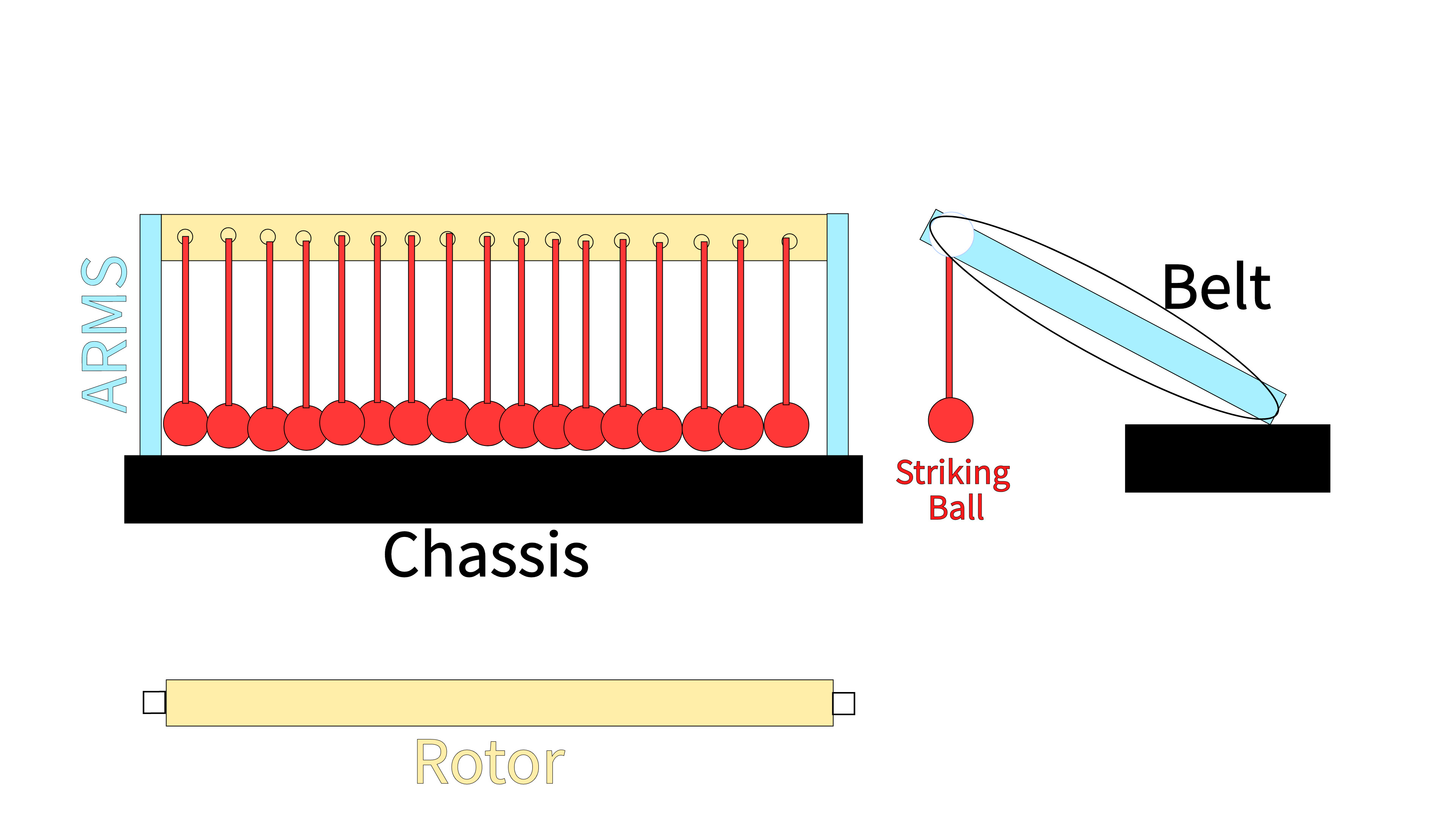
Flail Tool Concept SketchOur tool functions exactly like a mine flail. However, instead of triggering mines, the hanging elements are used to strike the target button. A motor installed on the chassis drives a belt attached to the rotor, driving its rotation.
We split the design of all components in three. Adrian took care of the arms, Lynn of the striking balls, and I designed the rotor.
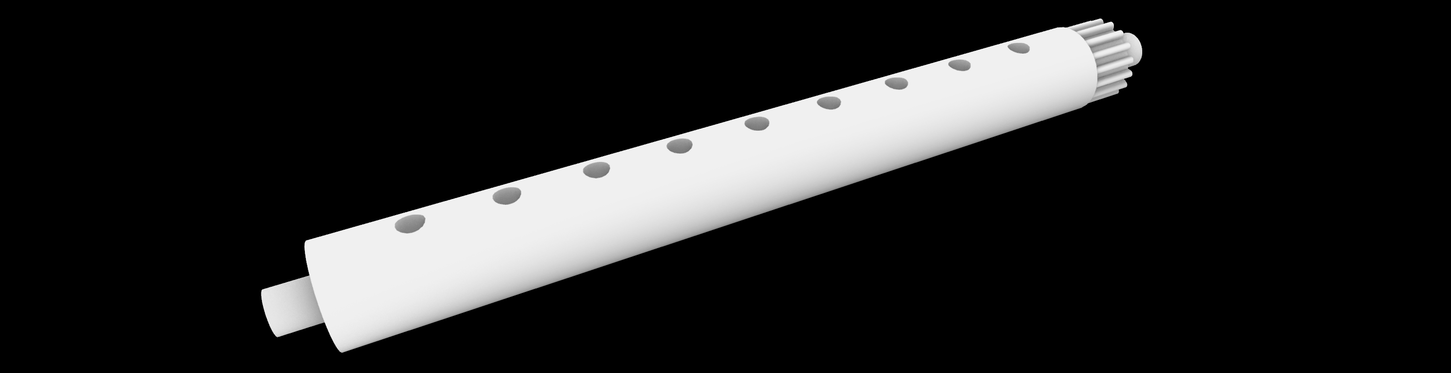
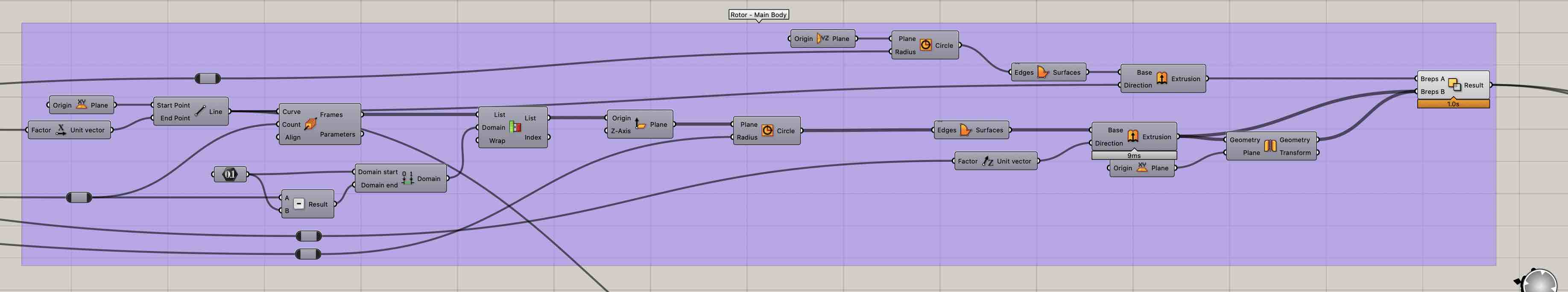
B. Designing the Rotor
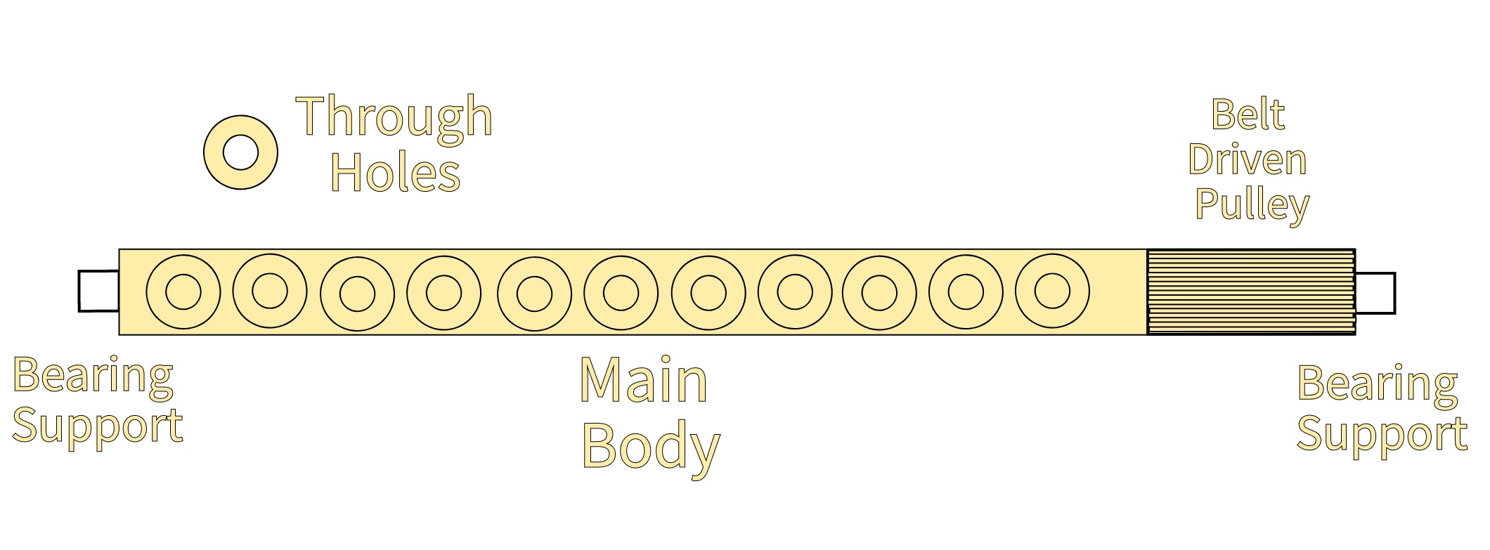
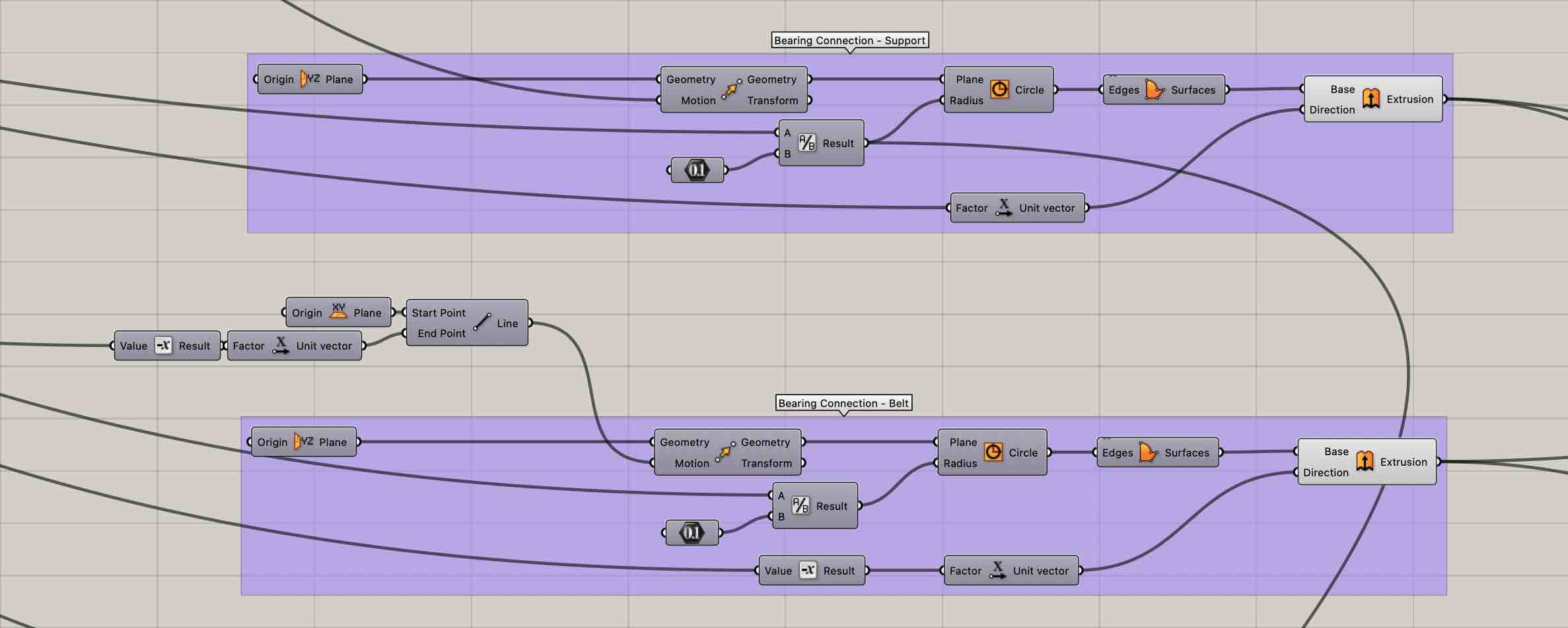
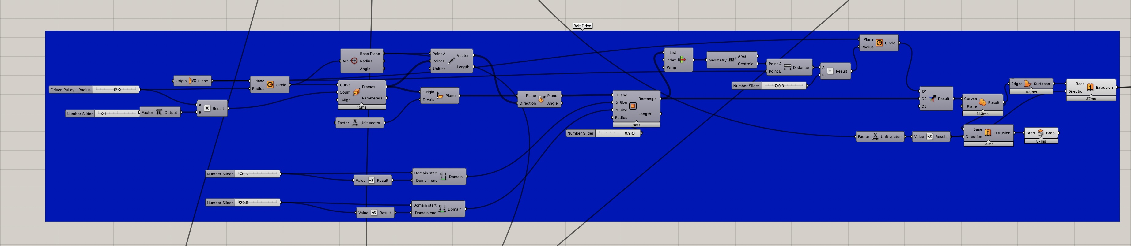
Rotor Concept SketchBuilding on my previous experience with grasshopper, I designed a program that would allow me to easily adjust the dimensions of each part of the rotor.

II. Machine - Power Train
1. Understanding Stepper Motors
a. Brushless DC Motors
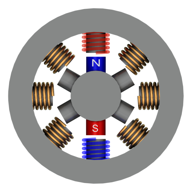
Stepper motors are essentially brushless DC motors (bDC). At the core of a bDC motor is a polarised magnet, known as the rotor, surrounded by windings/coils, acting as electromagnets, and also reffered to as the stator.
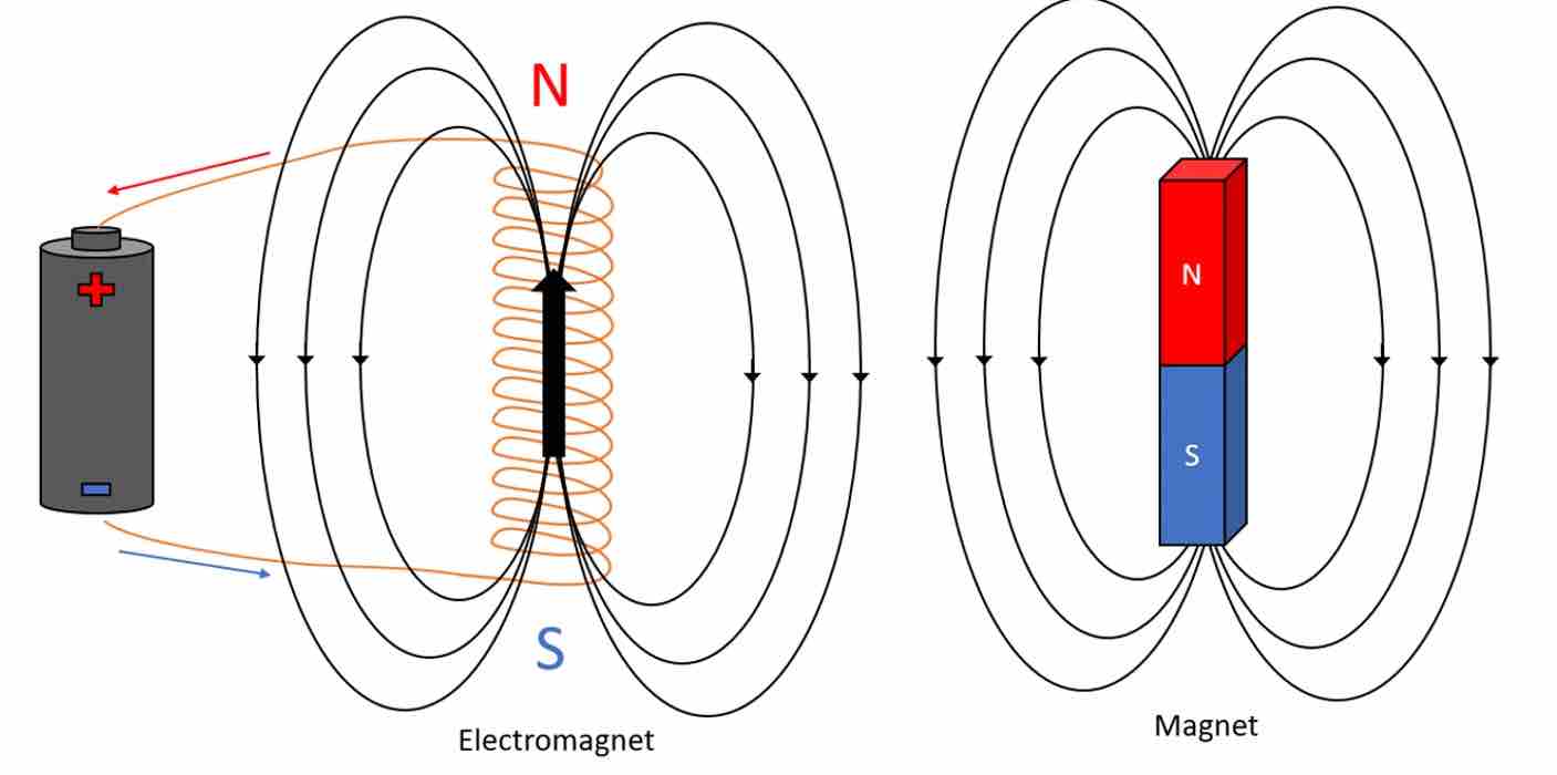
Electromagnet (Left) and Magnet (Right)The stator, as opposed to rotor, is the static element of a motor that actively participates in the production of the output movement. Let us assume the rotor magnet is surrounded by three electromagnets as shown in the below GIF.
Feeding current to a coil in a particular direction generates an electromagnetic field whose poles can be inverted by feeding current in the opposite direction. By feeding current to two coils in opposing directions and opposing sides of the magnet induces the rotor into motion as it attempts to align its poles with those of the electromagnets.
Sequenced Activation of Coils generating a rotary motion of the rotor in a brushless DC motorIn essence, the controllability of bDC motors is limited as it is not possible to know with exact certainty in what position the rotor is. Rotational speed can be manipulated, allowing for estimations to be made. However, this process is not ideal for precise endeavors.
b. Stepper bDC Motors
In contrast to pure bDC motors, stepper motors do allow for position control. This is because of its multi-pole rotor. In short, each magnet, or pole combination, constitutes a specific position. By activating the corresponding electromagnets, the rotor can be moved position by position. While this reduces the resolution by which the rotor moves and thus the “smoothness” of the rotary motion, it offers great positional control and ease of use, as detailed in section 2.
Stepper Motor2. Controlling Stepper motors
The Barcelona lab had a few NEMA standardised stepper motors whose characteristics are listed in the below table. The power train was designed around these.
Motor Characteristics (As listed on Datasheets)
| Motor | Steps(Resolution) | Phases | Dimensions | Holding Torque | Rated Voltage | Current | Operating Temperature | Quantity |
|---|---|---|---|---|---|---|---|---|
| NEMA11 | 200(1.8 degrees) | 4 | 36 mm | 9.1 N.cm | 12V DC | 1.8A @ 4V | -10 to 40 °C | 4 |
| NEMA17 | 200(1.8 degrees) | 4 | 33 mm | 42. N.cm | 12V DC | 1.8A @ 4V | -10 to 40 °C - | 5 |
a. Drivers
The control of our motors requires the generation of a square wave whose frequency is defined by the amount of time the program allows before it changes the state of the signal it outputs. The sample time (time it takes for the wave’s pattern to repeat itself) defines the rotational speed at which the motor operates.

Square WaveController circuits run on low current signals, yet motors need high current signals to operate. Motor drivers are interfaces used to convert low current control signals to high current ones.
b. Arduino Code
Test Code
1 2 3 4 5 6 7 8 9 10 11 12 13 14 15 16 17 18 19 20 21 22 23 24 25 | |
c. Effect of delays
The Arduino abstraction features four seperate commands used to introduce time-based functions. These are defined below.
| Command | Description |
|---|---|
| delay() | Pauses the program for the amount of time (in milliseconds) specified as parameter. (There are 1000 milliseconds in a second.) |
| delayMicroseconds() | Pauses the program for the amount of time (in microseconds) specified by the parameter. There are a thousand microseconds in a millisecond and a million microseconds in a second. |
| millis() | Returns the number of milliseconds passed since the Arduino board began running the current program. This number will overflow (go back to zero), after approximately 50 days. |
| micros() | Returns the number of microseconds since the Arduino board began running the current program. This number will overflow (go back to zero), after approximately 70 minutes. |
As described above, using delay functions pauses the whole program for the defined amount of time. As such detection of inputs will be halted until that amount of time has elapsed, thus preventing control over the system. On the other hand, millis()/micros() returns the amount of time elapsed since the board began running. This value is computed internally, and, depending on how the program is written, can allow for time considerations to be implemented without causing an interruption.
Following the tutorials found in link 3.2, We first came up with the following solution:
1 2 3 4 5 6 7 8 9 10 11 12 | |
Here, a while loop is used to create a time interval between changes in motor state. However, In this sequence, the while loop acts basically as a delay function would. We therefore modified it to the below. The new structure functions around an if loop. If the desired time has elapsed then the state of the motor is changed and the values keeping track of the elapsed time are reset. This means that changes only occur when the specified threshold is met without pausing the program. This is the logic we implemented in our program
1 2 3 4 5 | |
References
References
1. Motors
2. Drivers
3. Test Code
3.1. Arduino documentation and references
3.2. Arduino Programs that do multiple things at the same time
Assignment Files
Mechanical Design Files
Grasshopper Program - Used for the design of the rods and belt driver
STL Files - Used to Setup the printing of all components
GCode Files - Used to print the rods and the 24mm belt driver