Final project
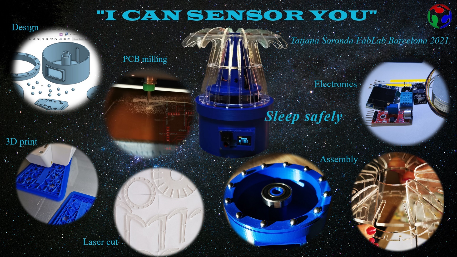
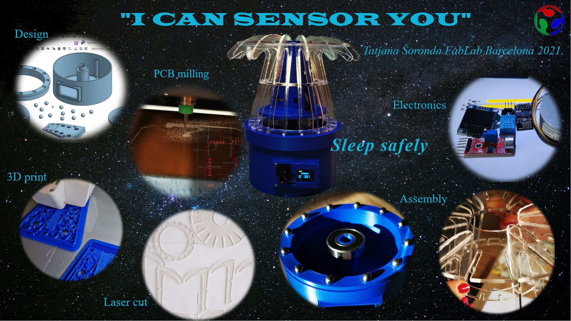
- *I CAN SENSOR YOU*
- DESIGN
- 3D PRINT
- LASER CUTTING
- ELECTRONICS
- PROGRAMMING
- Display of data obtained from sensors and microphones on the OLEd display
- PRESENTATION OF THE FINAL PROJECT
 The idea for my project came from my son’s health condition. With the very beginning of FabLab I had a few ideas,
however after my son suffocated and struggled for air while sleeping I came up with the idea for my project.
Since I had to constantly watch his breathing during the night and I was not allowed to fall asleep I sought the help of technology.
Because he likes the light on during sleep - night light,
I came up with the idea to incorporate light and sensors.
My idea is to make a night lamp that will contain a temperature and humidity sensor and a microphone.
The monitor is connected to the user's phone and sends an alert when it senses a change in temperature or breathing.
It can be useful for people that have sick children or family members and want to be able to keep an eye on them.
The idea for my project came from my son’s health condition. With the very beginning of FabLab I had a few ideas,
however after my son suffocated and struggled for air while sleeping I came up with the idea for my project.
Since I had to constantly watch his breathing during the night and I was not allowed to fall asleep I sought the help of technology.
Because he likes the light on during sleep - night light,
I came up with the idea to incorporate light and sensors.
My idea is to make a night lamp that will contain a temperature and humidity sensor and a microphone.
The monitor is connected to the user's phone and sends an alert when it senses a change in temperature or breathing.
It can be useful for people that have sick children or family members and want to be able to keep an eye on them.
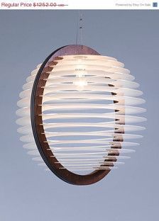
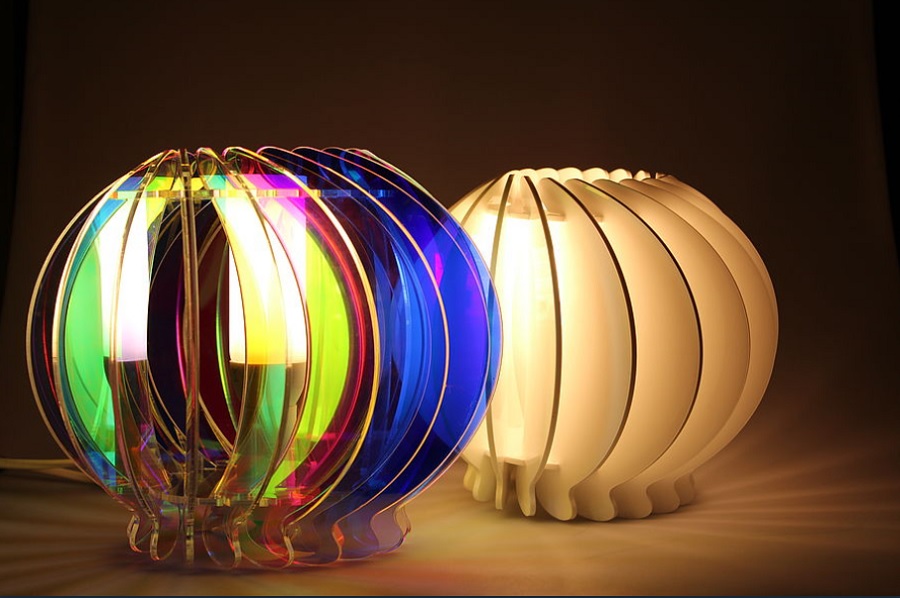 I looked for similar ideas and found a
few ideas similar to mine in appearance
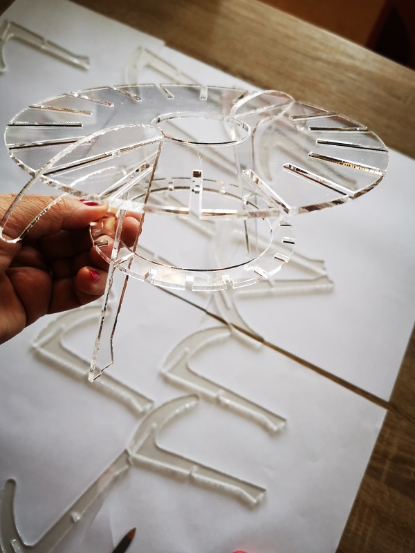
The lamp will be a combination of 3d prints and parts of plexiglass since it will be my son’s lamp.
I looked for similar ideas and found a
few ideas similar to mine in appearance
The lamp will be a combination of 3d prints and parts of plexiglass since it will be my son’s lamp.
Since the diagnosis is sleep apnea plus the primary diagnosis of DS for my son,
that means - a big problem, because it can all cause a heart attack, stroke, etc.
After the diagnosis, I started researching the diagnosis itself, but also help.
Sleep disorder - light
Obstructive-sleep-apnea#risk-factors
Philips - smartsleep
Assistance is in the form of operations that are not currently being performed due to COVID.
The next choice was technology.
Something similar to my project - lamp or sensors:
Abdelrahman Elshakankery
Tin Valetic
Baptiste LARDAIS
Yuki Oka
Noora Nyberg
What will you design?
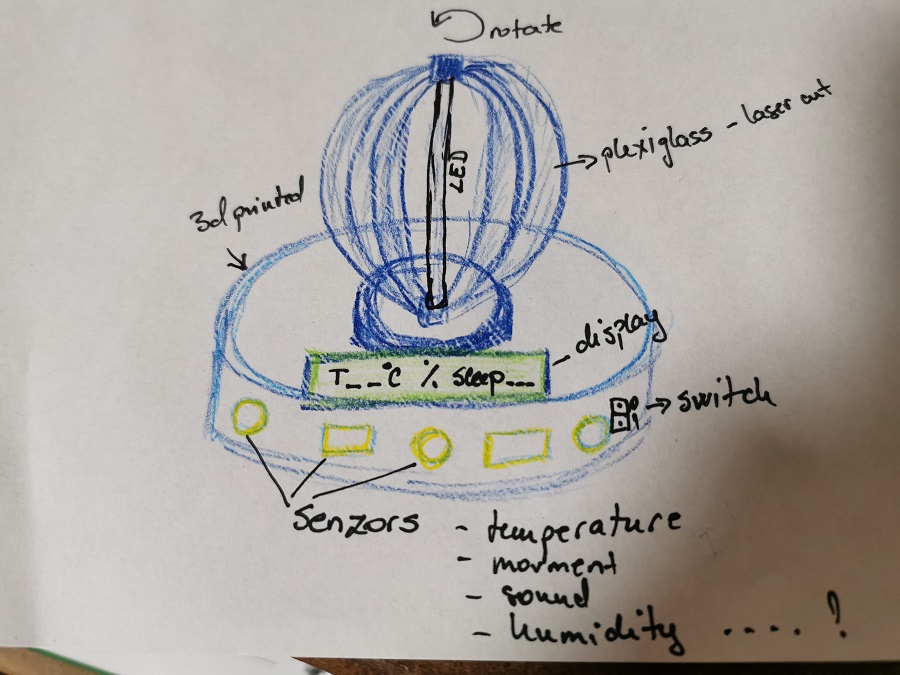
I will design the lamp completely: - the stand, the base where the sensors are located, the motor, and the PCB board, - the rotating mushroom-shaped part made of lamellae, - the upper part where the LEDs are located. Then I will design: - PCB board with which I will control the sensors and an application that monitors the operation of the sensors and informs about the parameters.
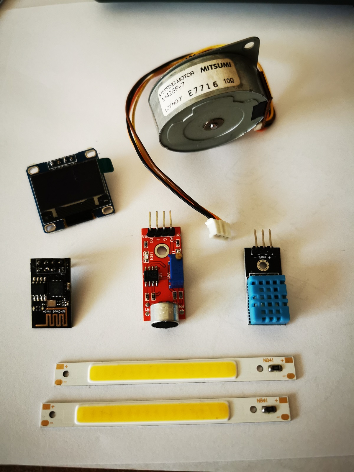
What materials and components will be used?
I will use: - PLA filament 2,85 mm, dark blue, for parts printed on a 3D printer - Plexiglass -3 mm for laser cut parts - Microphone Sensor High Sensitivity Sound Detection Module For Arduino - Mitsumi M35SP-9T Stepping Motor - Arduino Digital Temperature/Relative Humidity Sensor DHT11 Module - Geekcreit® 0.96 Inch 4Pin Blue Yellow IIC I2C OLED Display Module - DC3.7V 3W 80x7.5mm COB LED Strip Bar Light Warm Cold White - MCU AVR 8-Bit 16KB Prog SOIC-14 - AZDelivery esp8266 ESP-01S WiFi Parent module
Where will come from?
I will procure the parts I need from: - marwiol.pl - ebay - Banggood - Amazon and - local stores.
How much will they cost?
- PLA filament 2,85 mm, dark blue - kg €16,50- 0,3 - €4,95 - Microphone Sensor High Sensitivity Sound Detection Module For Arduino - pcs €1,78 -1- €1,78 - Mitsumi M35SP-9T Stepping Motor - pcs €7,00 - 1 - €7,00 - Plexiglass - €28 m2 - 0.3 m2 - € 8.4 - Arduino Digital Temperature/Relative Humidity Sensor DHT11 Module - pcs €1,17 -1- €1,17 - Geekcreit® 0.96 Inch 4Pin Blue Yellow IIC I2C OLED Display Module - pcs €6,13 -1- €6,13 - DC3.7V 3W 80x7.5mm COB LED Strip Bar Light Warm Cold White - pcs €2,54 - 2 -€5,08 - MCU AVR 8-Bit 16KB Prog SOIC-14 - pcs €0,60 - 1 - €0,60 - AZDelivery esp8266 ESP-01S WiFi Parent module - pcs €3,33 - 1 - €3,33 - PCB: don’t know yet the summary cost of the components for my PCB so this one is going to be described on my Final project(link) site - Total - around - €40
What parts and systems will be made?
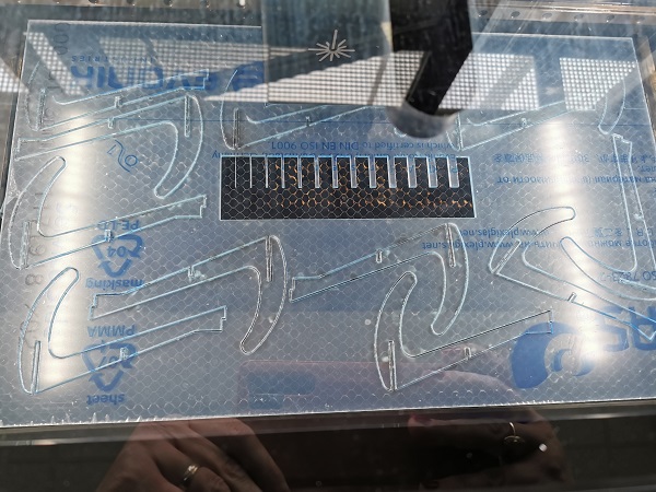
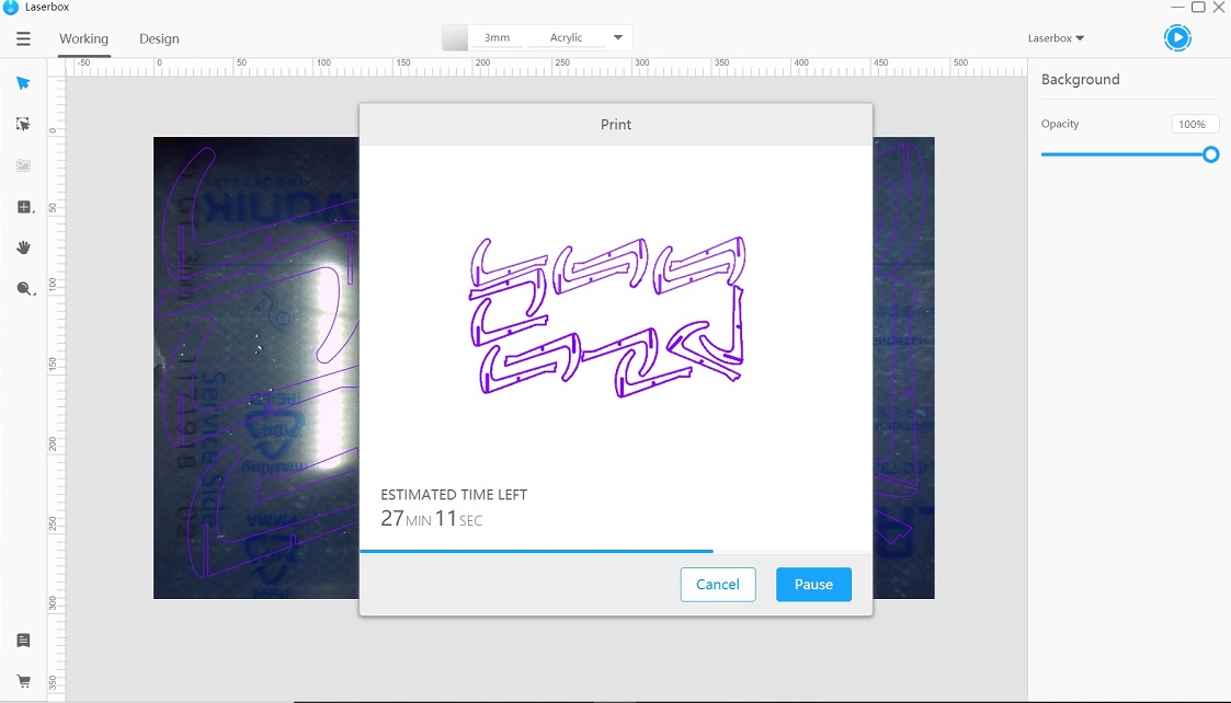
- Housing for electronics, electronics - Lamp base, rotating bracket, LED holders will be printed on a 3D printer, lamp lamellas will be made of Plexiglas and cut with a laser cutter
What processes will be used?
To create my project I used: - to design parts to be cut and printed - Onshape program - I used SketchUp Pro 2021 with addons to make the upper part of the lamp - I used the Ultimaker 3D printer and the Ultimaker Cura program to make 3D parts - I used KiCad to make a schematic representation of the PCB board - I will use a Roland MDX-15 CNC milling machine to make the PCB board - The chip is programmed using Arduino IDE. - I will use Arduino IDE and Blynk application on my mobile phone to create a mobile application.
What questions need to be answered?
Questions I still need to answer: - will the lamp be stable enough ? - will I successfully solder and program all components on the PCB board? - Will I successfully connect the lamp and mobile phone?
How will it be evaluated?
I think that my lamp should be evaluated depending on the success of reading the temperature and humidity in the room and the display on the oled display, reading the noise level - or the absence of the same . The lamp should be able to rotate in one direction after turned on / off from the switch.
BASE design
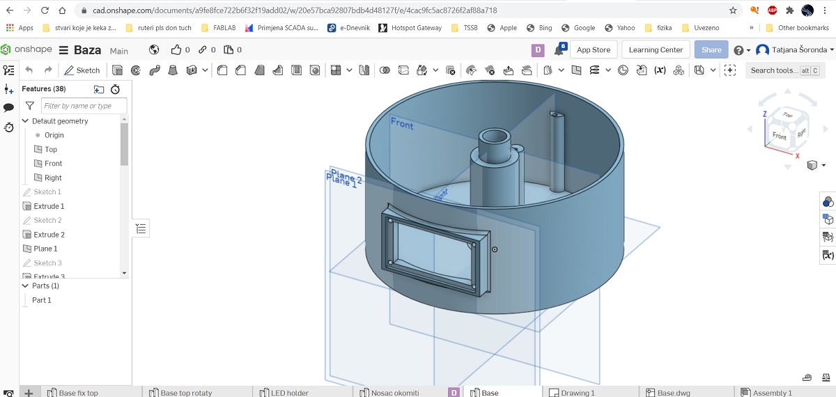
 After deciding how I wanted my lamp to look, I started with 3D Modeling.
I will do 3D modeling using the Onshape program.
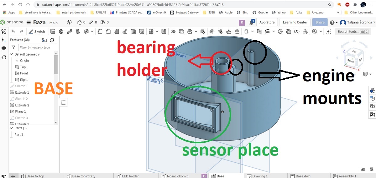
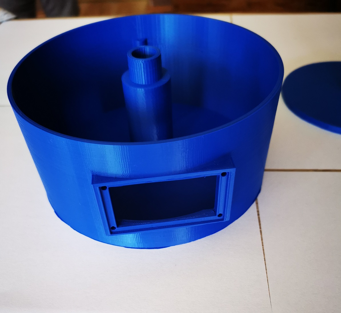
Inside the base will be a motor that rotates the top plate with the slats, a bearing with which to rotate the base of the slats,
a PCB plate with which the sensors and the mobile device will communicate.
There will be sensors on the front.
After deciding how I wanted my lamp to look, I started with 3D Modeling.
I will do 3D modeling using the Onshape program.
Inside the base will be a motor that rotates the top plate with the slats, a bearing with which to rotate the base of the slats,
a PCB plate with which the sensors and the mobile device will communicate.
There will be sensors on the front.
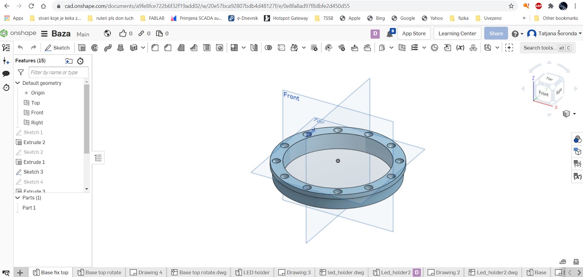
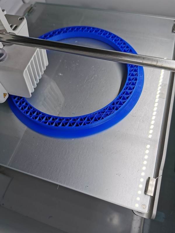
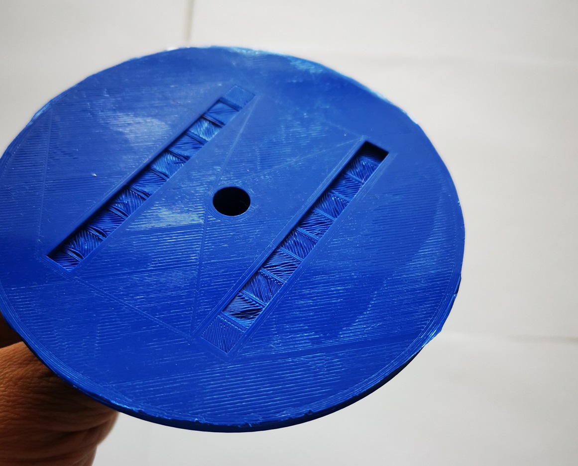
 A - Base top fix - is static part that comes to the base.
It has 12 holes with a diameter of 10 mm. I took them to the van bearing which is not working properly.
A - Base top fix - is static part that comes to the base.
It has 12 holes with a diameter of 10 mm. I took them to the van bearing which is not working properly.
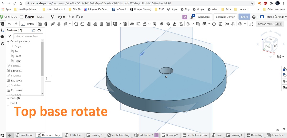
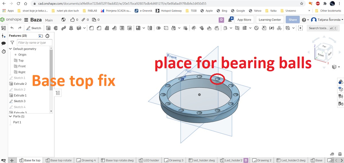
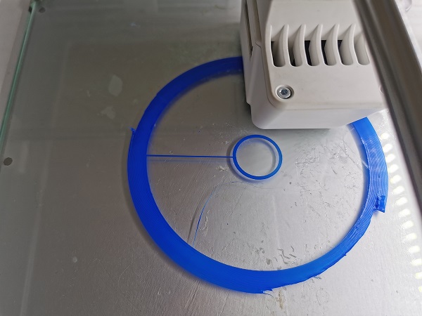
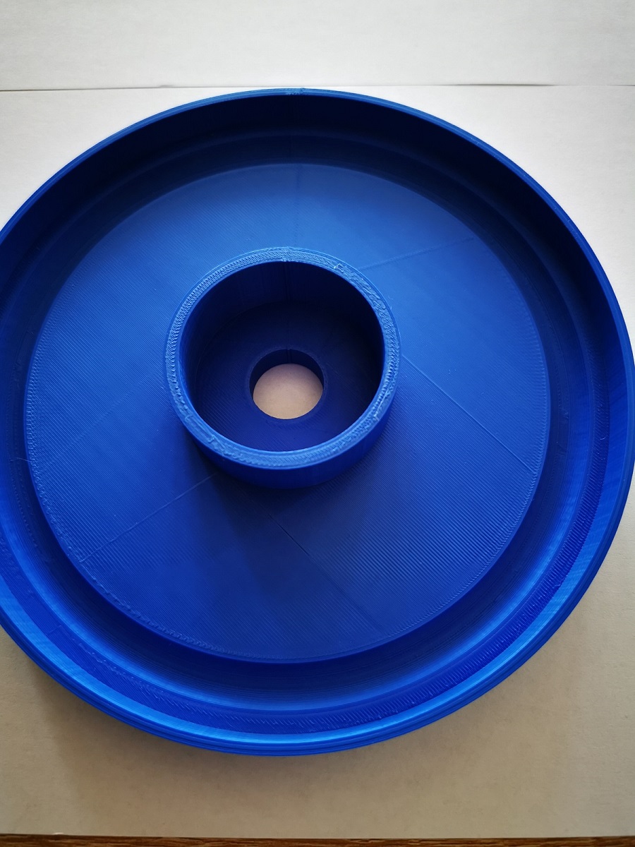
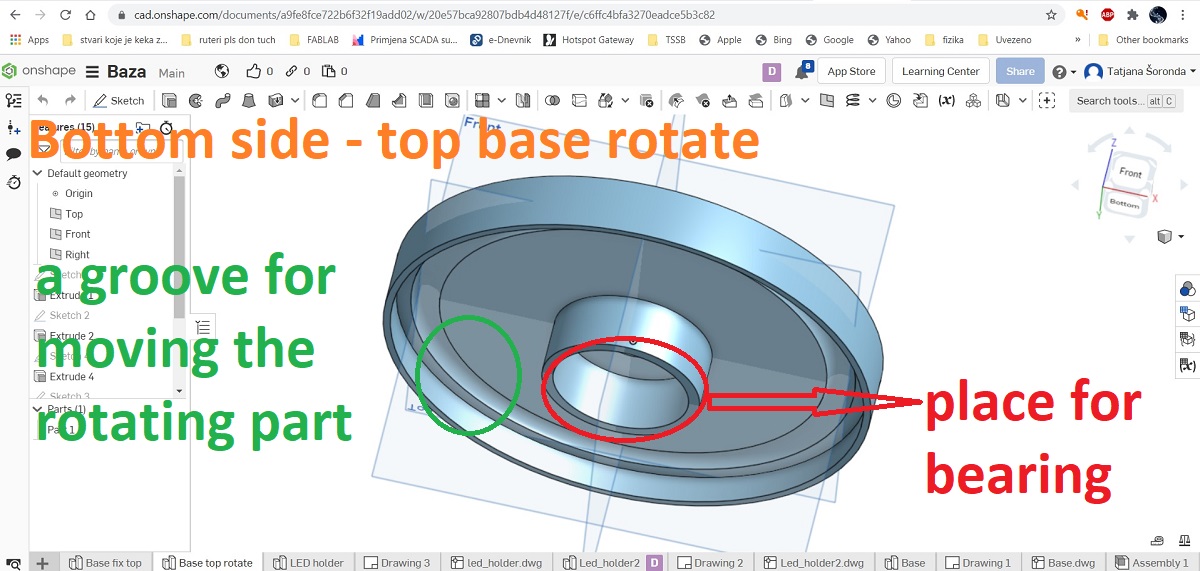 On the stationary part of the base comes the rotating part of the base that comes to the bearing and rotates using
a belt drive via the motor - Mitsumi M35SP-9T Stepping Motor.
The rotating part on the underside has a groove which makes it easier to move over the bearing balls.
On the stationary part of the base comes the rotating part of the base that comes to the bearing and rotates using
a belt drive via the motor - Mitsumi M35SP-9T Stepping Motor.
The rotating part on the underside has a groove which makes it easier to move over the bearing balls.
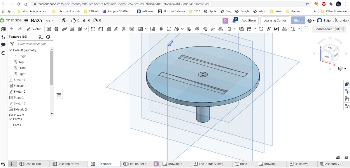
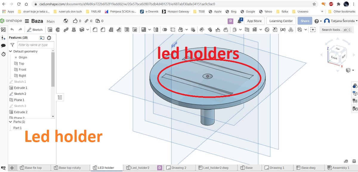 The next part is the LED holder. LEDs or vertical brackets can be placed in the grooves.
Brackets or slots are made for DC3.7V 3W 80x7.5mm COB LED Strip Bar Light Warm Cold White.
The next part is the LED holder. LEDs or vertical brackets can be placed in the grooves.
Brackets or slots are made for DC3.7V 3W 80x7.5mm COB LED Strip Bar Light Warm Cold White.
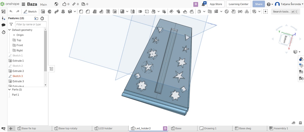
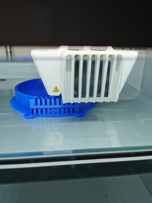
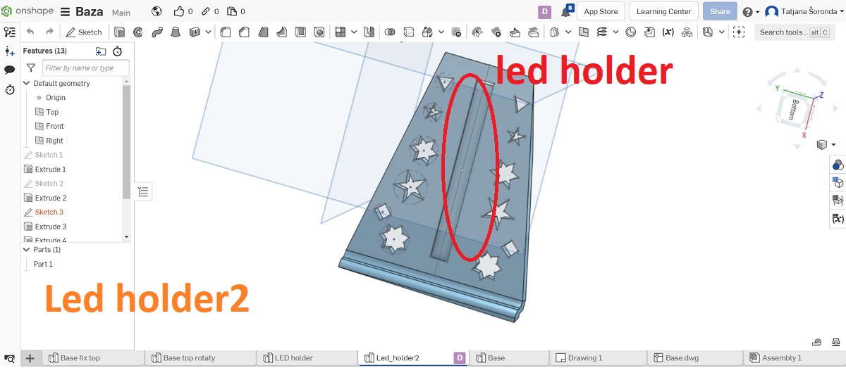 Vertical LED holder.
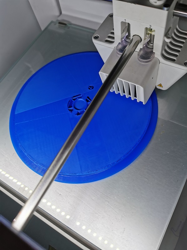 After designing the parts in Onshape, I exported each individual part to a STL file.
I used a Ulitimaker S3 3D printer to make the lamp parts.
I described the working principle of this printer and its characteristics in week 5 - 3D Scanning and Printing.
After designing the parts in Onshape, I exported each individual part to a STL file.
I used a Ulitimaker S3 3D printer to make the lamp parts.
I described the working principle of this printer and its characteristics in week 5 - 3D Scanning and Printing.
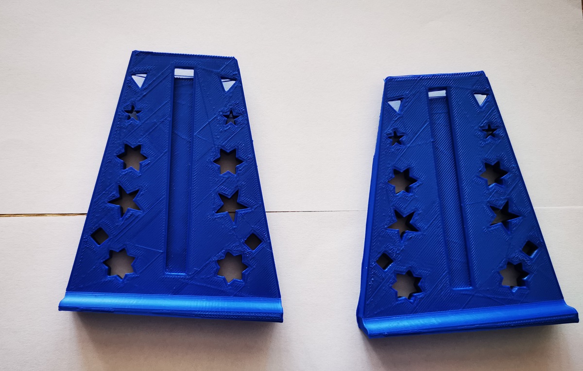
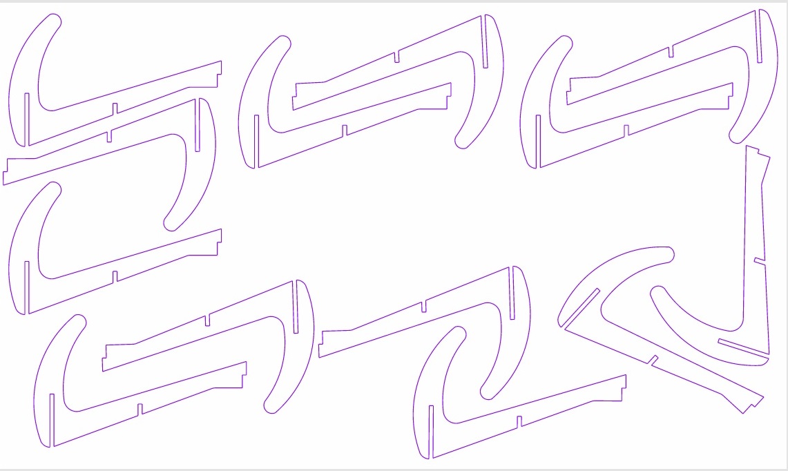
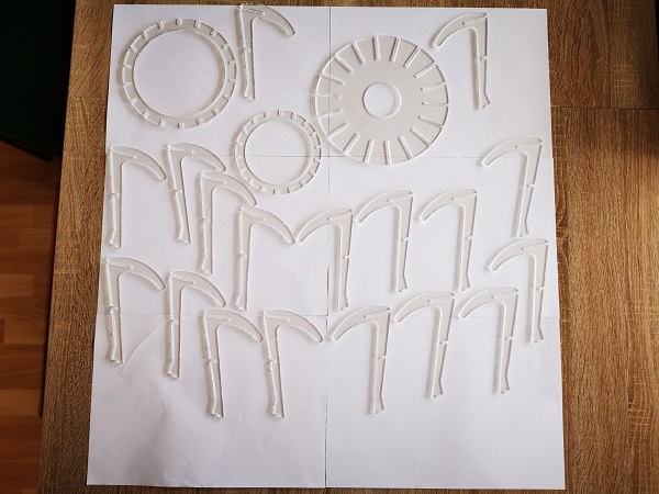
 The upper part of the lamp consists of lamellas.
First I drew that top in onshape and then with the help of Sketch up I made a slice of it
The upper part of the lamp consists of lamellas.
First I drew that top in onshape and then with the help of Sketch up I made a slice of it
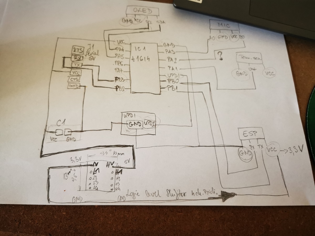
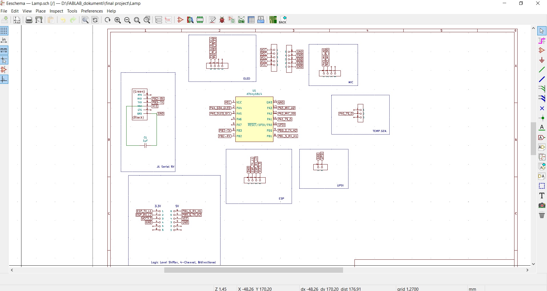
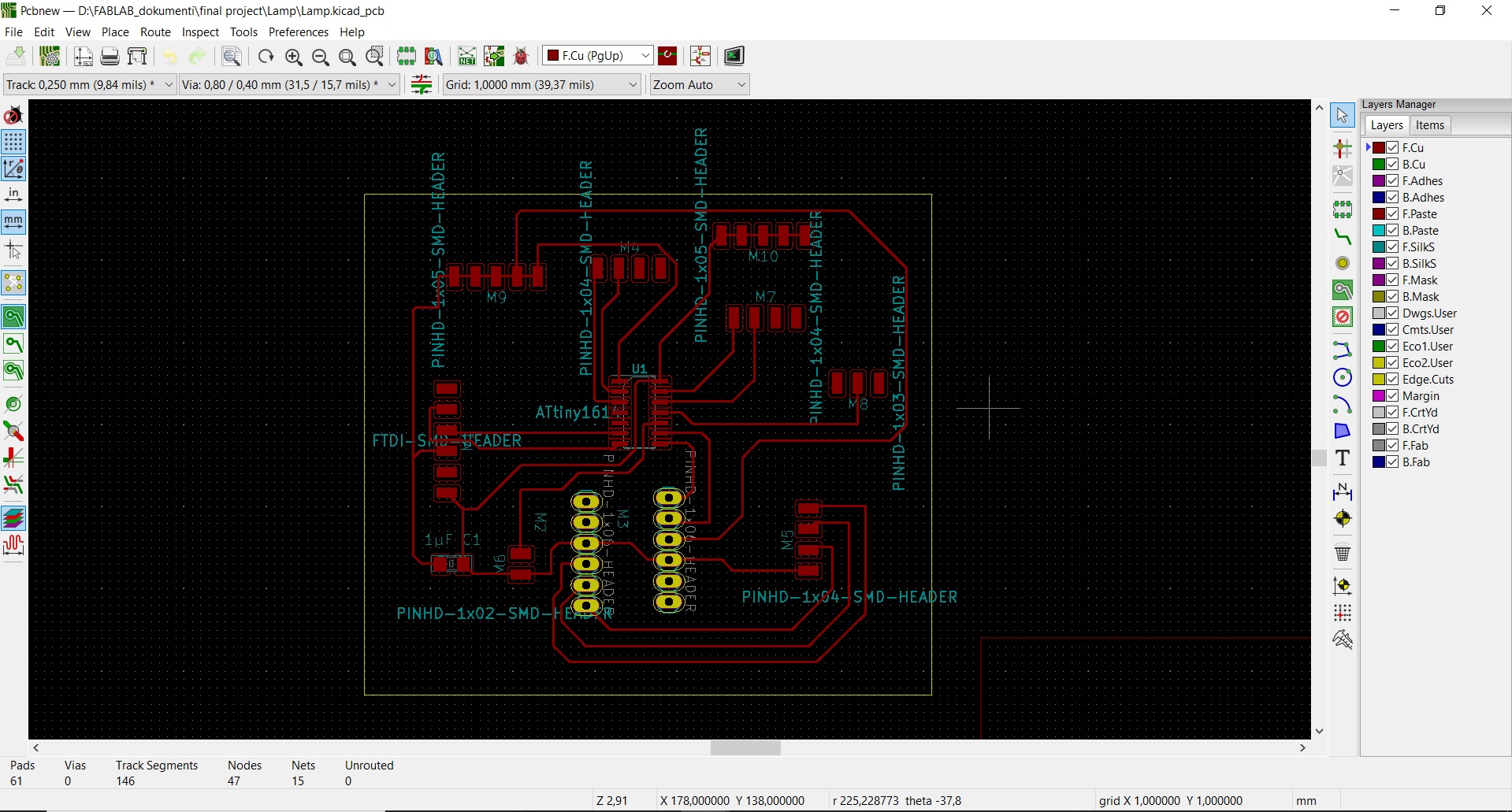
 For the needs of making PCB boards, I used the Kicad program.
I described how to work in this program in week 4-Electronics Production.
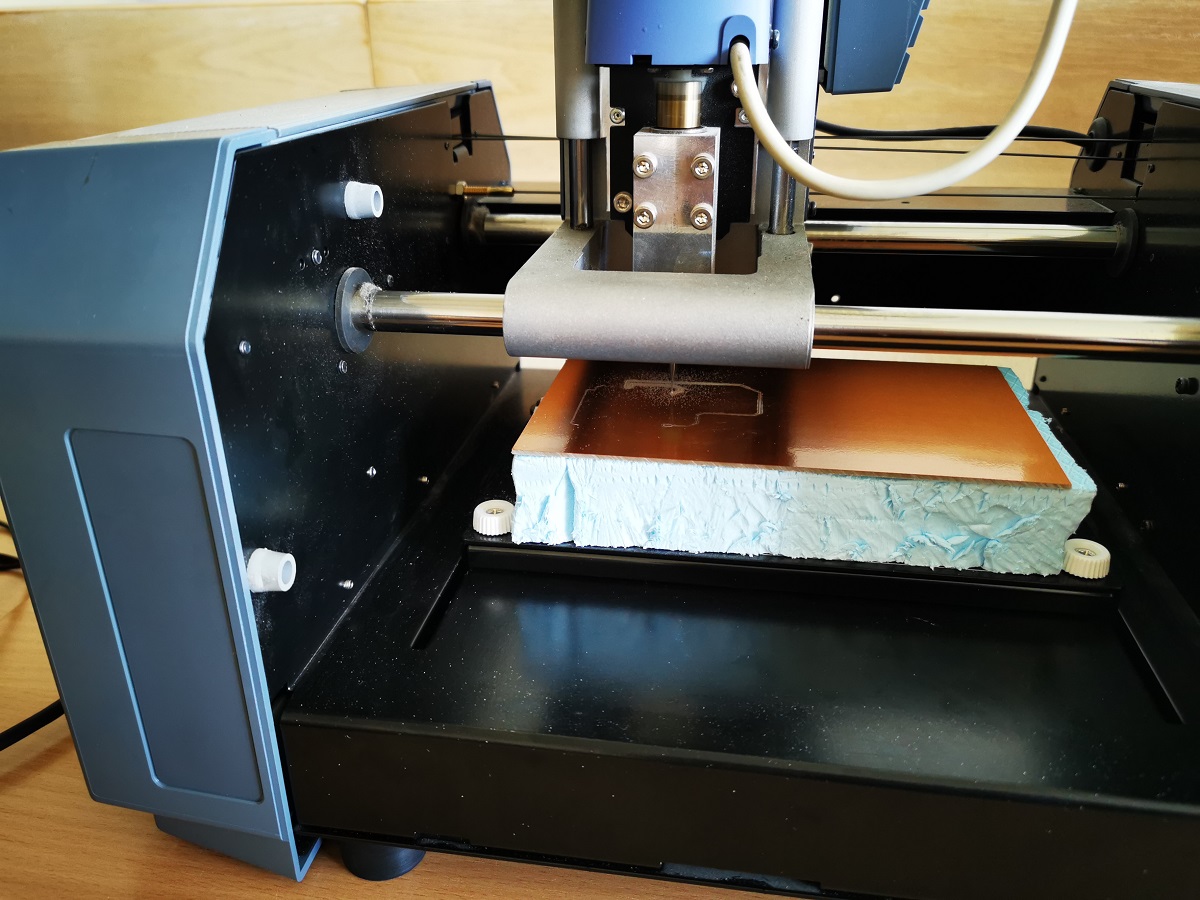
After making the scheme, I made the tile on MDX Roladn-15.
For the needs of making PCB boards, I used the Kicad program.
I described how to work in this program in week 4-Electronics Production.
After making the scheme, I made the tile on MDX Roladn-15.

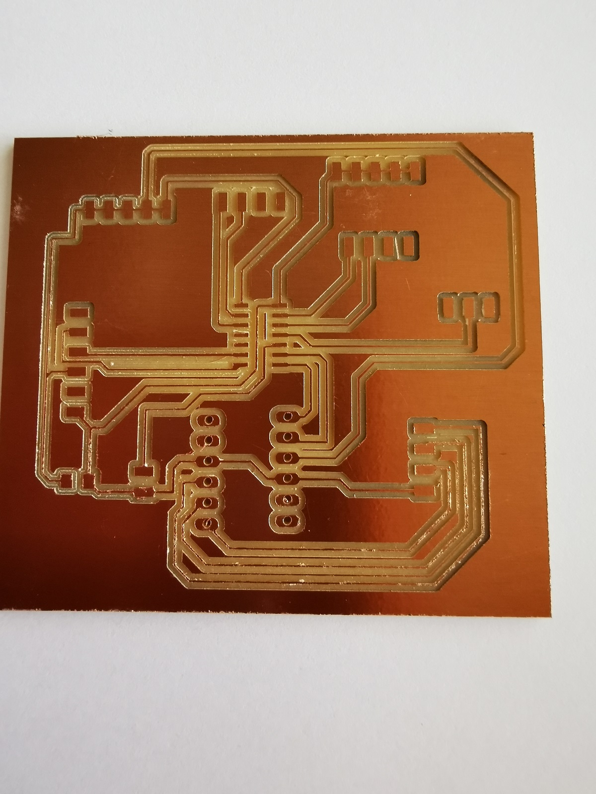 After making the board, it was necessary to solder the necessary components to the PCB board.
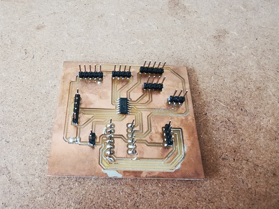
 When I soldered the necessary components to the board, I started programming it.
I programmed using the Arduino IDE.
When I soldered the necessary components to the board, I started programming it.
I programmed using the Arduino IDE.
i = 0;

							//I can sensor You
.
.
.
void sendSensor()
{
  float h = dht.readHumidity();
  float t = dht.readTemperature();
  if (isnan(h) || isnan(t)) {
  Serial.println("Failed to read from DHT sensor!");
    return;
  }
  display.setTextColor(WHITE);
  display.setTextSize(1);
  display.setFont();
  display.setCursor(0, 43);
  display.println("Temp  :");
  display.setCursor(50, 43);
  display.println(t);
  display.setCursor(90, 43);
  display.println("C");
  display.setCursor(0, 56);
  display.println("Hum   :");
  display.setCursor(50, 56);
  display.println(h);
  display.setCursor(90, 56);
  display.println("%");
}
.
.
.

}
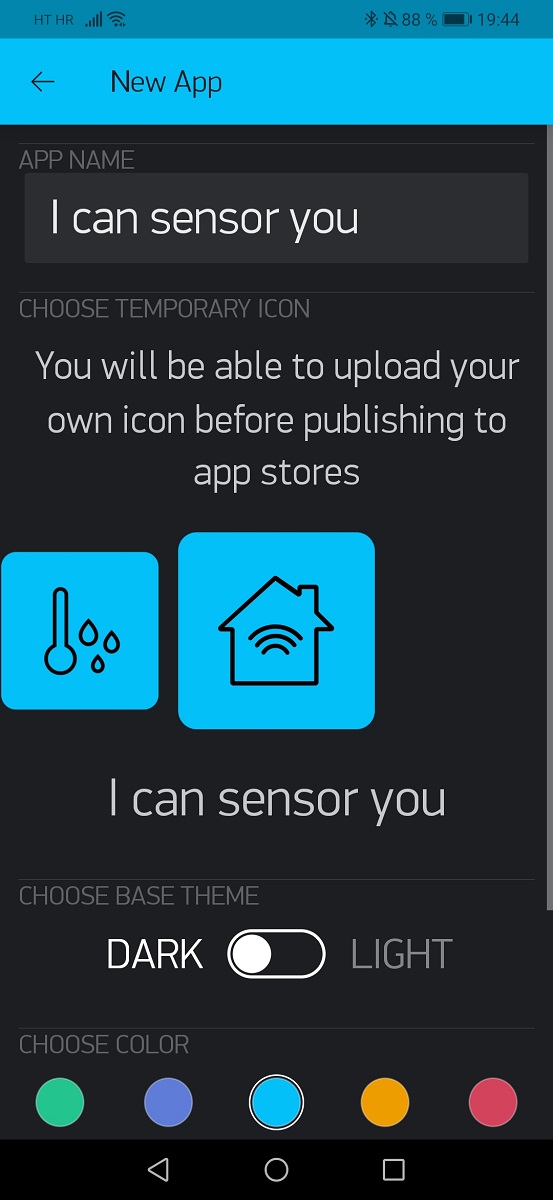
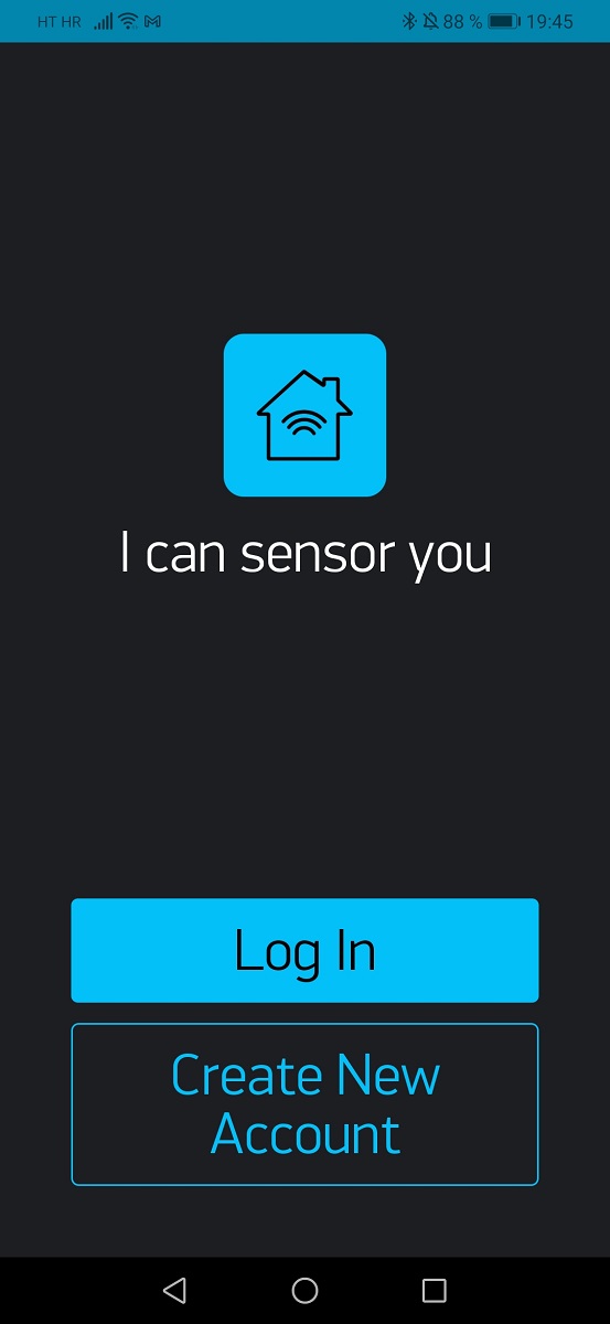 I used the Blynk application and ESP8266 to connect the PCB or the lamp and the mobile device.
I described how to work in this program in week 15Interface and Application Programming.
I used the Blynk application and ESP8266 to connect the PCB or the lamp and the mobile device.
I described how to work in this program in week 15Interface and Application Programming.