8. Embedded programming
Individual assignment
- Read a microcontroller data sheet
- Program your board to do something in as many different programming languages and environments as possible
Reading a data sheet
For this week’s assignment, I decided to use my button board that I had already designed and created during Electronics design week. The most important parts of that board are the ATtiny412 microcontroller, a button, an LED, and a few other necessary parts. When designing this board during Electronics design week, I referenced the data sheet for the ATtiny412.
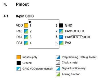
When doing this, I mostly looked at page 13 since that is where the the pinout was described.
The pinout of a chip is a diagram that illustrates what each pin is capable of and its main role and purpose. Using the key below, one could find that pin 1 is the power supply and pin 8 is ground.
Programming the board in different languages & environments
For this aspect of the week’s assignment, I will attempt to replicate the simple button code in as many languages as possible. More details about the board itself and the process of making it can be viewed on my week 6 page.
C++ with Arduino libraries
As mentioned earlier, this was the same board I had designed in week 6. To program this board, I started off by using the Arduino IDE and all of the Arduino libraries that offer intuitive commands such as “digitalWrite()” and “digitalRead()”, both of which I use in this program.
Blinking an LED
Blinking an LED is very simple with the Arduino libraries. This is the code I run for any board to test if it is receiving instructions. The first thing I did was make a variable for the LED pin so that I could just type the name of the variable and not the pin number every time. Then, in the “void setup()”, I assigned the LED pin as an output. In the “Void loop()”, I turned on the LED, waited 1 second, turned off the LED, waited a second, etc.
int led = 0;                  // sets the LED pin

void setup() {
  pinMode(led, OUTPUT);       // sets the pin 0 as an output
}

void loop() {
  digitalWrite(led, HIGH);    // turns on the LED
  delay(1000);                // waits for 1 second

  digitalWrite(led, LOW);     // turn off the LED
  delay(1000);                // wait for 1 second
}
Using a button
The button code is a bit more complex than simply blinking an LED. Like the blinking LED, I will first set some variables for the pins of each device, choosing the names “ledPin” and “buttonPin”. I also have to set a variable called “buttonState” which will be used later in the “if” statement. In “void setup()”, I will designate ledPin as an output device and the buttonPin as in input. I will also initialize the internal pull-up resistor on the button pin. Then, in the “void loop()”, I will start off by redefining the “buttonState” variable as the value of the button. The possible values are 1 (indicating the button is being pressed) or 0 (meaning the button is not pressed). Then, I will make an “if, else” statement. The condition that has to be met is that the “buttonState” variable has a value of 1. If it does, the LED will turn on. If it does not, then the LED will stay off.
const int buttonPin = 1;        // the number of the pushbutton pin
const int ledPin =  0;          // the number of the LED pin
int buttonState = 0;            // variable for reading the pushbutton status

void setup() {
  pinMode(ledPin, OUTPUT);          // sets the LED pin as an output
  pinMode(buttonPin, INPUT);        // sets the button pin as an input
  digitalWrite(buttonPin, HIGH);    // this turns on or activates the internal pull-up resistor on the chip for the button pin
}

void loop() {
  buttonState = digitalRead(buttonPin); // redefines the buttonState variable as a 1 or 0 based on whether the button is pressed or not

  if (buttonState == HIGH) {    // if the button is pressed
    digitalWrite(ledPin, HIGH); // turn on the LED
  }
  else {                       // otherwise ...
    digitalWrite(ledPin, LOW); // turn off the LED
  }
}
C++ with bare metal programming
While the Arduino libraries are very helpful when writing code, there is a tradeoff in terms of storage capacity and overall performance. One of my teachers, Mr. Dubick, shared a document with links to tutorials about “bare metal programming”, a method that can help avoid the use of these libraries. I had never heard of bare metal programming, but the man in this video explains it very well and offers an example of writing a simple blink program in this format. He explains how by directly contacting each port instead of using the commands from the Arduino library, he can run I am by no means an expert in bare metal programming, but I definitely will use it in the future since will be very useful when programs get increasingly more complex. He is using an Arduino Uno, but he references the data sheet to find which ports correspond to which pins which is a technique I used in the exact same way, except for my ATtiny412.
Before actually programming anything, I had to find all the ports that I used and find their correct names. I linked my LED to pin 2 which corresponds to “PA6” and my button is connected to pin 3 which is “PA7”. PA6 stands for “Port A 6”, meaning the LED is on the 6th pin of Port A. The same methodology is used to figure out that the button is connected to the 7th pin of Port A.
Blinking an LED
Since I have never used bare metal programming, I started off by making a simple blink program. Since the “delay()” function is a part of the Arduino library, I have to use a different method for making that delay. To do this, I made a simple “for loop” where it counted from 0 to 2,000,000 and anytime the value was in that range, the LED lit up. Once the counter reaches 2,000,001, the condition is no longer satisfied and it goes to the next part of the loop which is the same thing, but with the LED being turned off instead of on. This basically makes the processor perform an unnecessary action that has no effect on the outcome except for that fact that time is spent satisfying the conditions for the loop. The only aspect of this version of a loop that is not ideal is that this loop gives the processor a certain amount of tasks to complete and not a time frame in which to complete them. As you can see in the video below, the timing is not perfectly 1 second on, 1 second off, 1 second on, 1 second off, etc.
void setup() {
  PORTA.DIR = 64;                                      // 01000000 sets PA6 to output and all others as input
}

void loop() {
  PORTA.OUT = 64;                                      // turns on the LED
  for (long i = 0; i < 2000000; i++){PORTA.OUT = 64;}  // runs a time-consuming loop to maintain the LED as on

  PORTA.OUT = 0;                                      // turns off the LED
  for (long i = 0; i < 2000000; i++){PORTA.OUT = 0;}  // runs a time-consuming loop to maintain the LED as off
}
Using a button
After learning to blink using bare metal programming, I wanted to take it to the next step and use a button to light up the button. Since this code is a bit more complex and I am using an input and output device, I will use “bit masks” to address each bit individually. To address PA6 (where the LED is located), I will use “PIN6_bm”. To address PA7 (where the button is located), I will use “PIN7_bm”. In the “void setup()” I will have to do all the same things as before, set PA6 as an output, set PA7 as an input, and initialize the pull-up resistor for PA7. To set PA6 as an output device, I will use the command “PORTA.DIRSET = PIN6_bm”. To set PA7 as an input, i will use the command “PORTA.DIRCLR = PIN7_bm”. To initialize the pull-up resistor I will use the command “PORTA.PIN7CTRL |= PORT_PULLUPEN_bm”. Then in “void setup()” I will have to make the “if, else” statement like before. I will start off with the conditional “if” statement. The condition will be whether an input is being received from PA7, so I will use the command “if (PORTA.IN & PIN7_bm) { “. Inside that “if” statement, I will set the LED pin to high by using the command “PORTA.OUTSET = PIN6_bm”. In the “else” portion of the statement, I will turn off the LED by using the command “PORTA.OUTCLR = PIN6_bm”.
void setup() {
  PORTA.DIRSET = PIN6_bm;               // sets PA6 as an output (for the LED)
  PORTA.DIRCLR = PIN7_bm;               // sets PA7 as an input (for the button)
  PORTA.PIN7CTRL |= PORT_PULLUPEN_bm;   // initializes the pullup resistor on the button pin
}

void loop() {
  if (PORTA.IN & PIN7_bm) {             // if the button pin is allowing voltage to pass (is pressed) ...
    PORTA.OUTSET = PIN6_bm;             // set the LED pin to 1 (or HIGH)
  }
  else {                                // otherwise ...
    PORTA.OUTCLR = PIN6_bm;             // reset the LED pin to 0 (or LOW)
  }
}
Tinker circuits
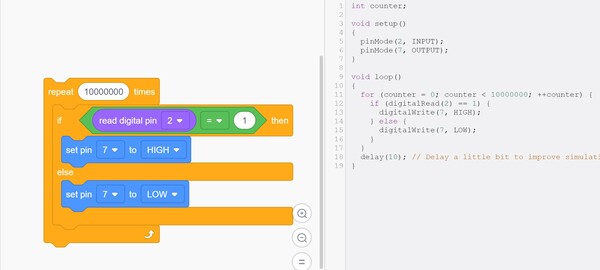
Tinker Circuits is a very easy program to use when making rough prototypes. There are 2 settings for programming a board or arduino: text-based code and block-based code. I decided to use the block-based code since my other languages were all exclusively text-based. This did not take long at all and was overall very easy to make.
All I had to do was take a “repeat” statement which repeats the function a set number of times. I choose the number 10000000, but this is an arbitrary value. Next, there is a basic “if, else” statement which states that if the button is pressed (value = 1), turn on the LED, otherwise keep the LED off.
This is an image of the block code that I used side-by-side with a text-based code that performs the exact same thing. As described in the comments, the delay of 10 milliseconds represented by “delay(10);” is just to make the simulation function more smoothly but has no substantial effect on the simulation itself.
Files
Blink code with Arduino libraries
Button code with Arduino libraries
Group assignment
- Compare the performance and development workflows for other architectures
More details can be viewed at this week’s full page