12. Output devices
- Add an output device to a microcontroller board you designed and program it to do something
Brainstorming and planning
On my final project, I will use 2 motors, one for rotating the sensor used in Input Devices week to find the ball and another for launching the golf ball back to the person practicing. I would only need about 180° of rotation for rotating the sensor and I think I will only need about 90° for the launcher since I am thinking of doing a catapult-type launcher. This means that the only output devices I need are servo motors.
General
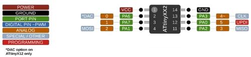
ATtiny412
The microcontroller I will be using for this week’s assignment is an ATtiny412:
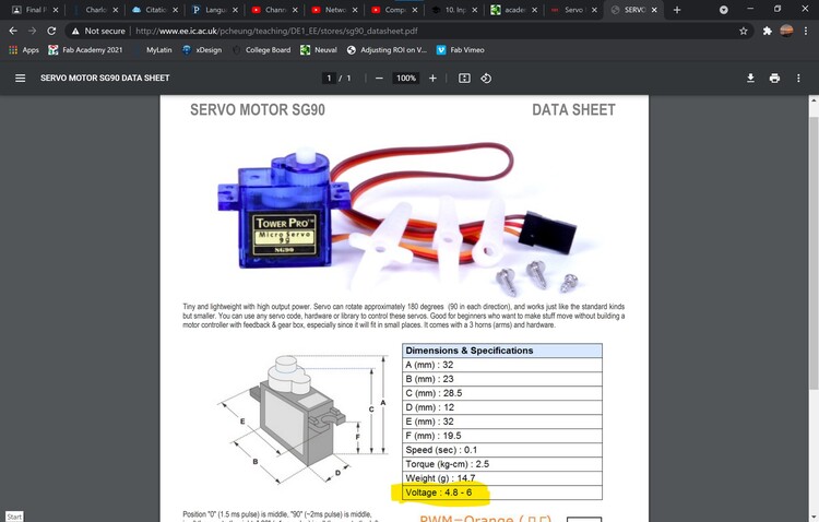
Servo
The servo I am using is a Servo Motor SG-90. The operating range for voltage input for this servo is 4.8 to 6 volts, so I will not a voltage regulator if I draw power from the 5V pin on an Arduino.
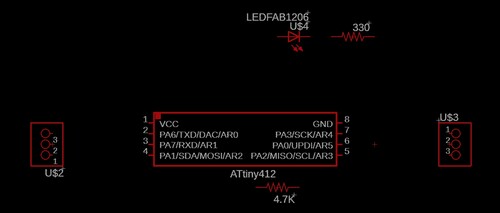
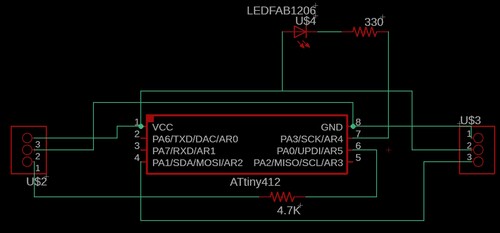
Designing the schematic in EAGLE
For this week’s design, I only had to use the fab_new library to design the schematic.
The only things I need for this schematic are an ATtiny412, a 4.7K Ω resistor (for UPDI), an LED (for testing), a 330 Ω resistor (for the LED), and header pins.
Designing the board in EAGLE
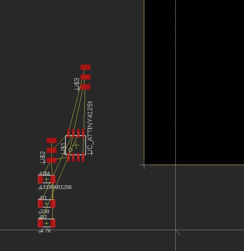
After switching the schematic to a board, my screen looked like this:
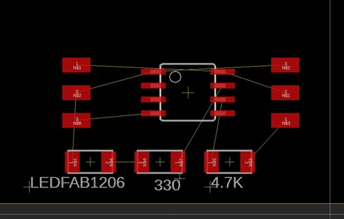
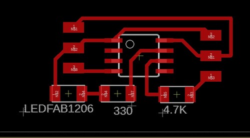
Then I rearranged all the pieces to minimize the wasted space between each component and then I drew the traces by hand with a trace width of 16:
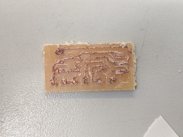
Milling
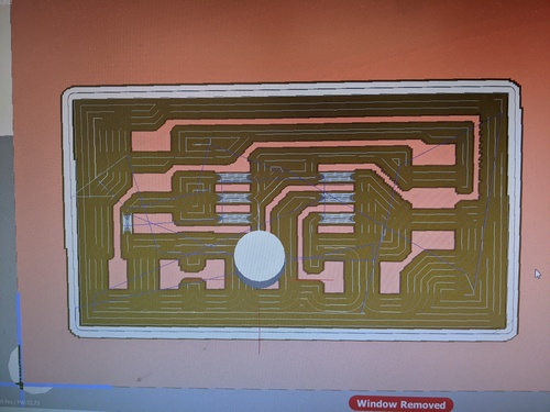
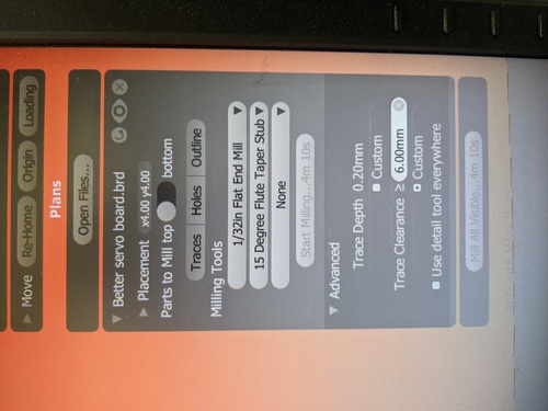
I’d say the only real issue I encountered was during the milling process. The first time I tried milling the servo board I had horrible traces as pictured below. I’m guessing this was a result of either a poor bit, an unlevelled bed, or runout that caused a wobbly and imperfect cutting axis.
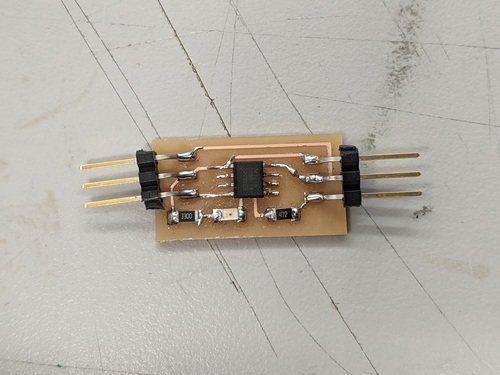
Soldering
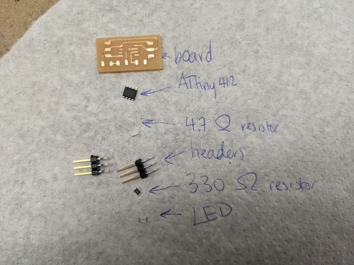
As seen in the board and schematic designs, I do not need many components:
- Board
- ATtiny412
- 4.7K Ω resistor (for UPDI)
- Headers (3 for programming and 3 for the servo)
- LED (for testing)
- 330 Ω resistor (for the LED)
Programming
Blink test
Like with any board, the first thing I want to test out is blinking an LED just to make sure that the board is receiving the program from my computer via the Arduino programmer. As mentioned before, the LED is on pin 4.
void setup() {
  pinMode(4, OUTPUT);
}

void loop() {
  digitalWrite(4, HIGH);
  delay(1000);
  digitalWrite(4, LOW);
  delay(1000);
}
Servo control
The first thing I wanted to do with the servo was just do a simple back and forth program, rotating 180 degrees in each direction. It would travel in the forward direction with a 5 ms delay between each step and move back with a 15 ms delay. This means the servo travels 3 times faster in the forward direction than in the backwards direction. This was a generic servo control code that I found on the Arduino website at this link
#include <Servo.h>

Servo myservo;  // create servo object to control a servo

int pos = 0;    // variable to store the servo position

void setup() {
  myservo.attach(9);  // sets the servo pin

}

void loop() {
  for (pos = 0; pos <= 180; pos += 1) { // Go from 0 degrees to 180 degrees w/ 5 ms delay
    myservo.write(pos);
    delay(5);
  }

  for (pos = 180; pos >= 0; pos -= 1) { // Go from 180 degrees to 0 degrees w/ 15 ms delay
    myservo.write(pos);
    delay(15);
  }

}
After I had that very simple back and forth code, I decided to make it a bit more complex to showcase my understanding of the code. This next version has a 90° turn with 5 ms delay, then 90° back (also with 5 ms delay). Then, the servo rotates 180° with a 15 ms delay between each step. Then the servo travels 90° towards the middle and then 90° back (both with the 5 ms delay). Then the servo goes moves back to 0° position and then repeats all those steps. This is similar to the first example code, except that the threshold for each “if” statement are changed and the delay between each step is changed depending on which state of the program the servo is completing.
#include <Servo.h>

Servo myservo;  // create servo object to control a servo

int pos = 0;    // variable to store the servo position

void setup() {
  myservo.attach(2);  // sets the servo pin

}

void loop() {
  for (pos = 0; pos <= 90; pos += 1) { // Go from 0 to 90 w/ 5 ms delay between each step
    myservo.write(pos);
    delay(5);
  }

  for (pos = 90; pos >= 0; pos -= 1) { // Go from 90 to 0 w/ 5 ms delay between each step
    myservo.write(pos);
    delay(5);
  }

  for (pos = 0; pos <= 180; pos += 1) { // Go from 0 to 180 w/ 15 ms delay between each step
    myservo.write(pos);
    delay(15);
  }

  for (pos = 180; pos >= 90; pos -= 1) { // Go from 180 to 90 w/ 5 ms delay between each step
    myservo.write(pos);
    delay(5);
  }

  for (pos = 90; pos <= 180; pos += 1) { // Go from 90 to 180 w/ 5 ms delay between each step
    myservo.write(pos);
    delay(5);
  }

  for (pos = 180; pos >= 0; pos -= 1) { // Go from 180 to 0 w/ 15 ms delay between each step
    myservo.write(pos);
    delay(15);
  }

}
Files
Group work
This week’s group assignment was to test the power consumption of an output device. The device that was tested was a 9V DC motor. To learn more about the group assignment, go to this page