Week 2: Computer-Aided Design
This week will be different from last week, as I’m proficient with 3D CAD and vector-based design software, so I’ll be trying to push the limits of my knowledge. I learned CAD in Fusion 360, and feel fairly confident with my skills in that program, but I have never used Solidworks, so I would definitely like to take this opportunity to gain a proficiency with a new program. I’ve done a decent amount of work in Adobe Illustrator, but I still feel like their are gaps in my knowledge with using the software, so this week I’m going to try to learn to use some tools that I don’t normally use. If this all goes well, I’ll play around with GIMP to do some pixel-based design, and Blender to do some more advanced animations.
Feb 3
I learned today that Solidworks doesn’t run on Mac OS, but my only computer is a Mac. This means that I’ll need to find a way to install Windows on my Macbook in order to download and use Solidworks. After some research, it looks like Apple does provide a relatively straightforward way to do this in the form of Boot Camp, which lets you partition your hard drive so you can run multiple operating systems on the same computer, and decide which one to run at the time of boot. Basically, I’ll need to download the Windows 10 disk image, then run the Boot Camp Assistant program on Mac OS to create a partition in my hard drive, then load the downloaded Windows 10 disk image onto it. Once I reboot the computer in Windows, I can register with a software key, download Solidworks, and register with the credentials provided to me by the 3D Experience Lab. While this does all seem simple enough, my hard drive is relatively small at 250 GB, and I am running very low on free space, so I will need to clear space on my hard drive before I can proceed with this process.
Feb 6
As mentioned above, I wanted to take some time to further my skills with vector based design software. I did this by recreating the sketch I made of my final project in Adobe Illustrator. I added an additional tool to my tool belt by incorporating gradients into the design to give a sense of depth. The gradient was not very difficult to get the hang of once I started experimenting with it. I added a circular gradient to the circle representing the well that holds the pills for one day. This gradient on the sides of the container gives the appearance that the well has depth, and the pill is not simply resting on the surface of the pill case. I also used the linear gradient tool to shade the pill itself.
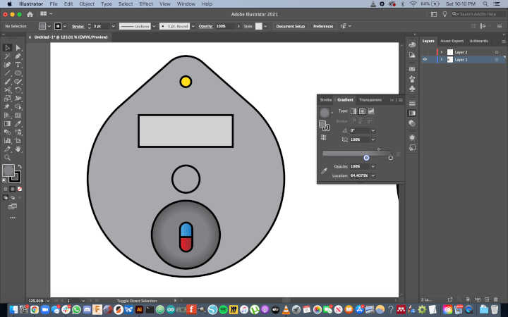
To give the suggestion of light emanating from the LED, I used the line tool to create one “ray of light”, then used the rotate tool to duplicate that line by selecting the circle representing to LED as the center point to rotate around.

To demonstrate that the button on the front face of the pill case would be a fingerprint sensor, I wanted to add a little finger print icon to the schematic. Rather than create the icon from scratch, I downloaded a free vector from Vecteezy.com
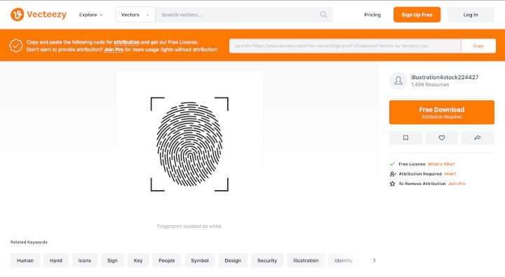
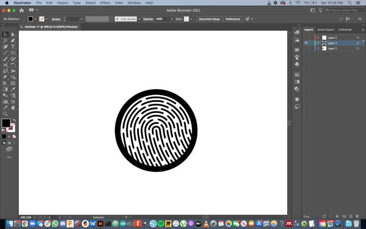
I then imported this vector into my schematic file, ungrouped the lines so I could select them individually, and used the circle representing the button as a guide to crop the lines of the fingerprint vector.
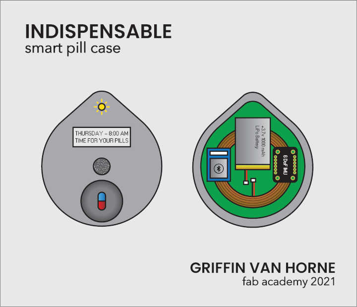
Overall, I’m very proud of how it turned out!
Pill Case Files:
Feb 9
While I was able to work in vector editing software this week, I ran out of time before I could model my final project in Solidworks. While much of this had to do with the unexpected complexity of clearing out and partitioning my hard drive, I was also limited in what I was able to accomplish because of other responsibilities I had to manage. I’m serving as a Teaching Fellow for Prof. Beth Altringer‘s Product and Experience Design for Desirability, a course cross-listed in Harvard’s SEAS and GSD. This week, it was coincidentally my responsibility to give the students an introductory tutorial in CAD, and help develop a design challenge to help the students put these new skills to work. This was the first time I’ve ever taught a CAD tutorial or developed a design challenge, so it did take me a significant amount of time to generate and edit the materials. While this did prevent me from diving into Solidworks, I feel that this was a very valuable experience.
The design challenge was centered around coffee mugs. Mugs are approachable and relatable. They’re common household objects that most people interact with on a daily basis. From a CAD perspective, a basic cylindrical mug can be modeled in a number of ways, using any of the four main tools that turn 2D sketches into 3D bodies (extrude, revolve, loft, and sweep). From a manufacturing standpoint, mugs aren’t very large, so once we decide the winner of the mug design challenge, we can get the mug printed in ceramic material on an SLS 3D printer through Kwambio. In order to prepare for this design challenge, I created a document highlighting the history of mugs, and included a case study on one of my favorite designed objects: the coffee cup lid. Here is an excerpt:

Since 7-Eleven started selling fresh hot coffee to go in 1964, Americans have been drinking coffee during their commute, but the experience wasn’t always ideal. It was 11 years before the first lid that could be peeled back and attached to itself, and it wasn’t until 1984 that the iconic Solo Traveler lid was invented. Today, somewhere around four billion cups of coffee are served per year between Starbucks, Dunkin’ Donuts, and McDonalds alone.
Coffee cup lids are a great example of products that are so ubiquitous that they’ve become invisible to consumers until they’re designed poorly. There are dozens of patents on coffee cup lids, all claiming to improve on design flaws of their predecessors, but the average person probably can’t tell them apart. But bad designs are everywhere, and one poorly designed lid can ruin a shirt or a laptop, and change a consumer’s future behavior. With the insane scale of modern manufacturing, billions of Starbucks’ new “straw-free” lids will be made every year. Poor execution of this design process could have had a massive negative impact on the company’s brand, their profits, and the environment.
Coffee cup lids are just one example of the subtly, and sometimes poorly, designed world around us. If we can think like a designer rather than a consumer, then we can observe and shape this world, improving the lives of those who live in it without some of them even noticing.
For the CAD tutorial itself, I spent a long time trying to distill the UI, core workflow, and key tools into a digestible format. I felt like I struggled to balance giving the students a solid base to grow from without overwhelming them. There are a number of shortcuts that I could’ve used to get them making simple objects faster, but when it comes time to make more complex objects, these shortcuts won’t do them any good, and they’ll need to learn the fundamentals anyway. One area where I could definitely improve for next time is with time management. I was hoping to go through some of the example models faster to provide more time for questions, but I got too buried in the details at certain points of the tutorial, and time slipped away from me. Luckily the tutorial was recorded, so I can look back at the video to analyze my performance. Here are the slides I created for the tutorial, and a Dropbox link to the video can be found here.
Apr 4
After spending a long time trying to sort out getting Solidworks up and running on my computer, it looks like I’ll need to install a new SSD in order to partition my disk and load Windows onto my laptop. Rather than waiting for this upgrade, I’m going to document one of my most recent CAD projects, using Autodesk Fusion 360 and Autodesk MeshMixer. The project I’ll be highlighting is a drinking vessel designed to be manufactured using Kwambio’s ceramic 3D printing service. I wanted to design a form that would be impossible to replicate using traditional manufacturing techniques, in order to highlight the benefits of additive manufacturing. To achieve this goal, I utilized voronoi patterns to achieve an organic form.
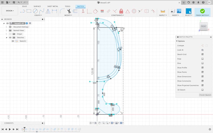
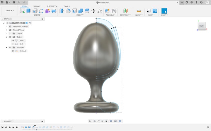
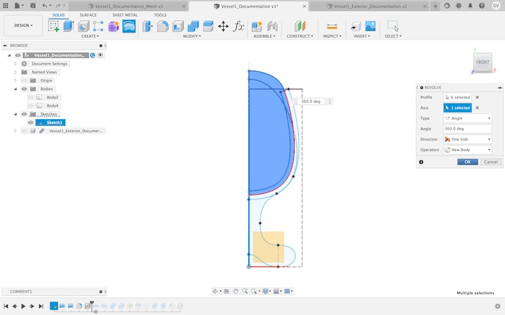
I first created a sketch and used splines to create the profile of the vessel.
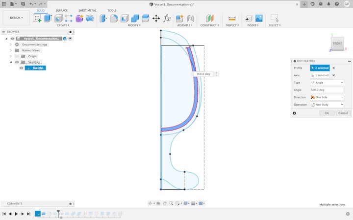
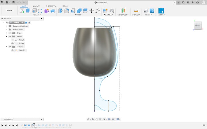
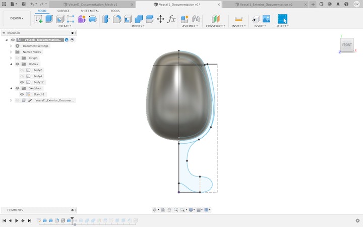
I then used the revolve tool to create the upper section of the vessel and a body that will be turned into the lower section.
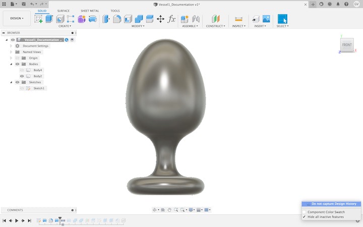
In order to apply a voronoi pattern to the lower body, I first had to convert it into a mesh. While the Model workspace lets you create and modify solid “B Rep” bodies, you cannot create or modify hollow “mesh” bodies unless you enter the Mesh workspace. The problem is that you cannot access this workspace unless you turn off the “Capture Design History” option, which prevents you from being able to access the timeline. For this reason, it’s important to save the file before you stop capturing design history, and save the file under another name once you start editing mesh, so you will still have the ability to easily modify the core design through the timeline.
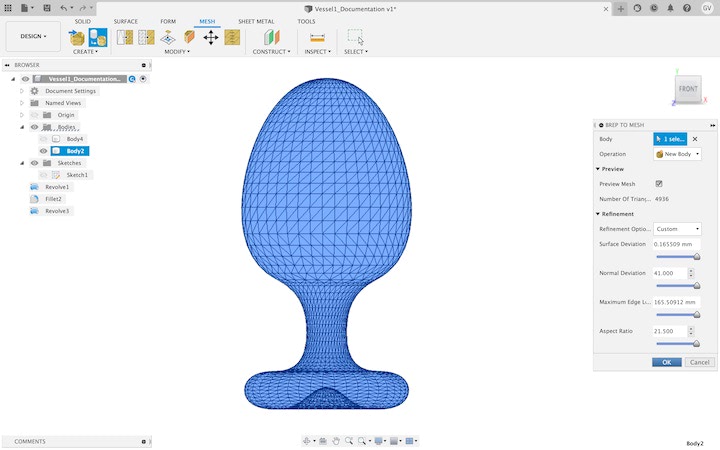
Once the “Capture Design History” option has been turned off, I entered the “Mesh” environment using the workspace selection tool at the top left corner of the screen. I then selected “B Rep to Mesh” in order to convert the model from a solid B Rep into a hollow mesh of triangles that represent the surface of the body.
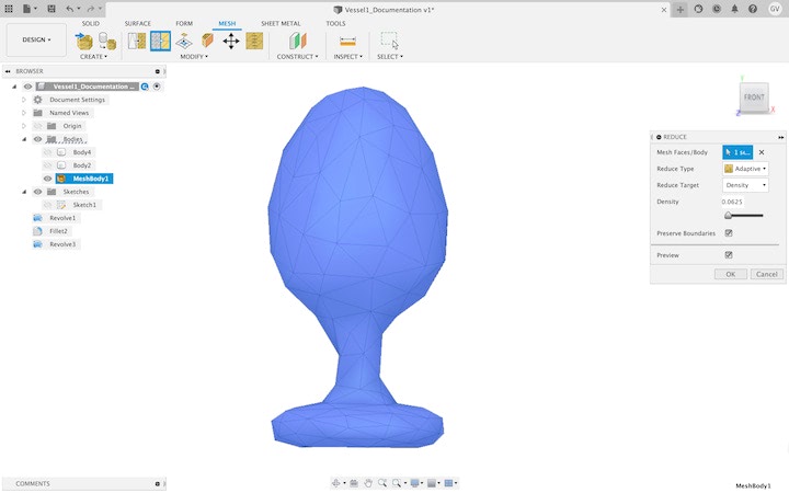
The number of voronoi cells will correspond to the number of faces that make up the mesh, so the next step was to reduce this down to a manageable number. In the “Reduce Mesh” panel, there is an option to preview the resultant mesh before finalizing the operation.
Once the number of faces was reduced, I selected “Tools” at the top of the screen, then clicked “3D Print,” selected the mesh body, and selected the “Send to 3D Print Utility” option.
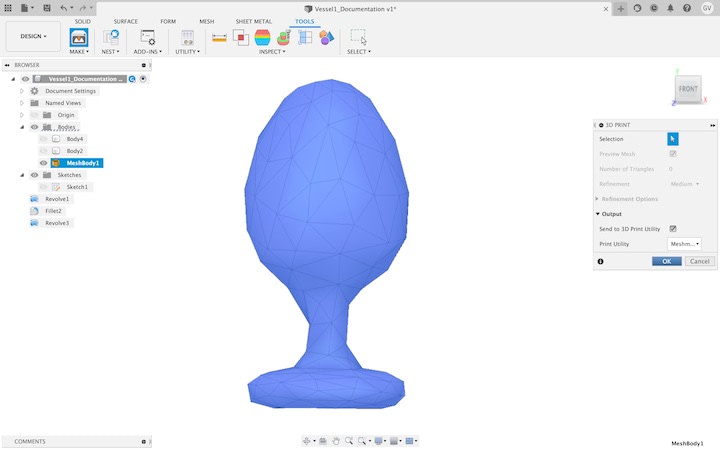
Once “OK” was pressed, Fusion 360 exported the model as a .STL file, and opened it in Autodesk Meshmixer.
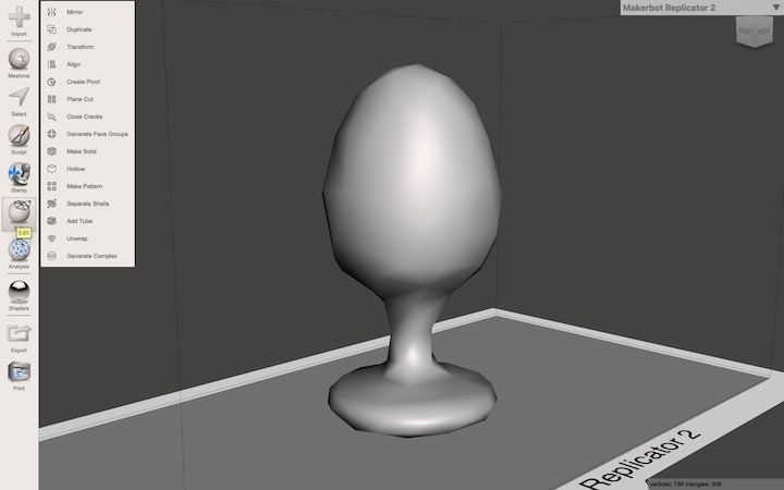
Once opened in Meshmixer, I clicked on the “Edit” icon on the toolbar on the left of the screen, then selected “Make Pattern.”
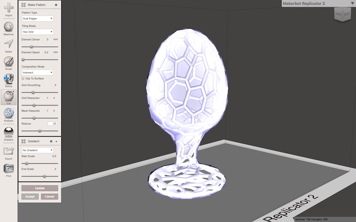
In the “Make Pattern” window, I selected the “Dual Edges” pattern type, the “Hex Grid” tiling mode, and the “Intersect” composition mode. I set the “Element Dimensions” to be 3 mm to match the wall thickness of the upper part of the drinking vessel, the “Grid Smoothing” to 2 to slightly smooth out the vertices where the elements meet, and the “Reduce” to 25. All other options were left at their default settings.
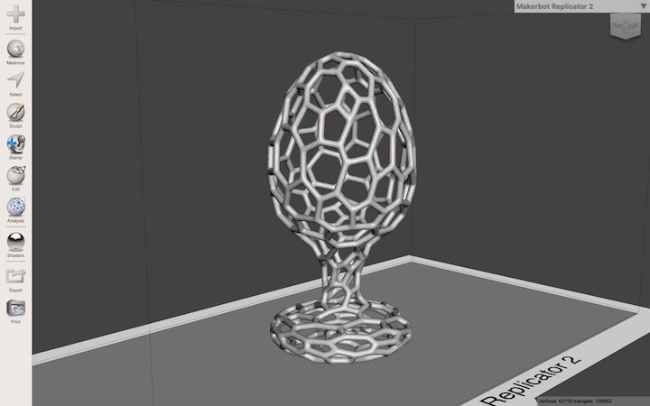
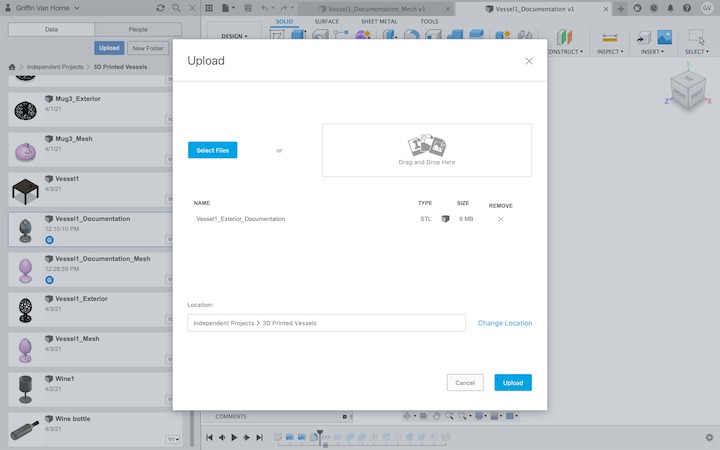
I was pleased with the result, so I exported the model as a .STL file and reopened Fusion 360. I then uploaded the new mesh file into Fusion 360 using the upload button in the Data Panel.
Once uploaded, I reduced the number of faces on mesh using the same process as detailed above.
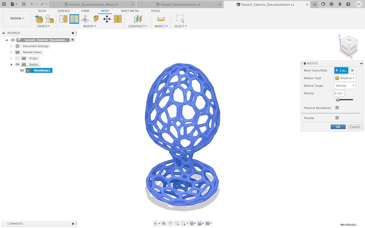
This step is important, as you will be unable to convert the mesh back to a B Rep if it has too many faces.
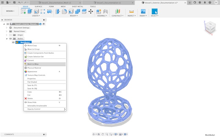
I then reentered the Model workspace, right-clicked on the model in the Browser, and selected “Mesh to B Rep.”
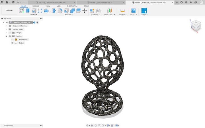
I now had a solid body that could be inserted into the original design file and modified in the Model workspace. In order to do this, I opened the original file, opened the Data Panel, then right clicked on the thumbnail for the solid voronoi model file and selected “Insert Into Current Design.”
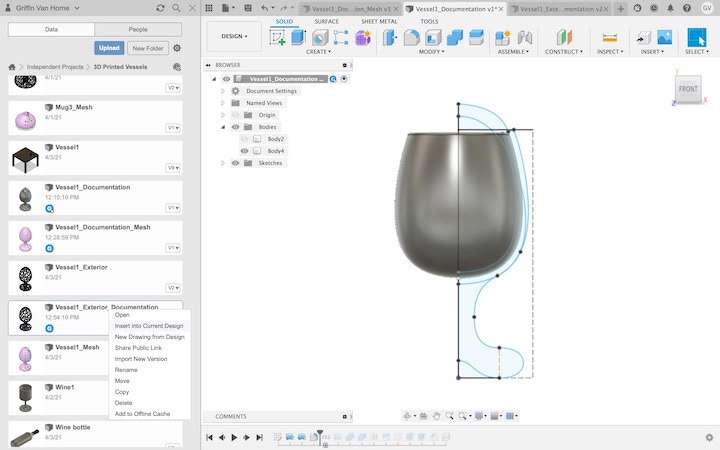
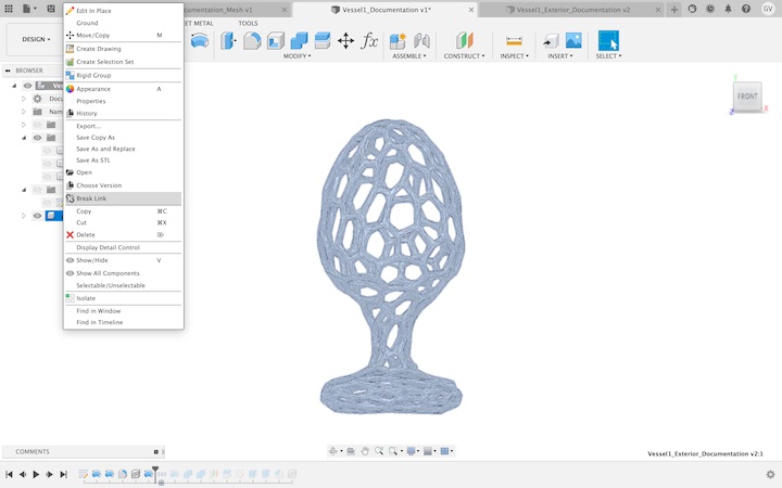
Once the model was inserted, I repositioned it to be in the correct position relative to the upper part of the drinking vessel. I then right clicked on the solid voronoi model in the Browser and selected “Break Link” so I could modify the model in the file I had just inserted it into.
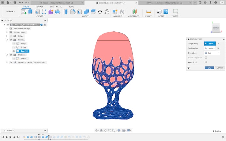
I then used the revolve tool to create a body that would serve as a tool I could use to cut away the section of the voronoi body that I wanted to get rid of.
Once this body was created, I used the Combine tool, selecting the voronoi solid body as the target, and the new body as the tool, and setting the operation to “Cut.”
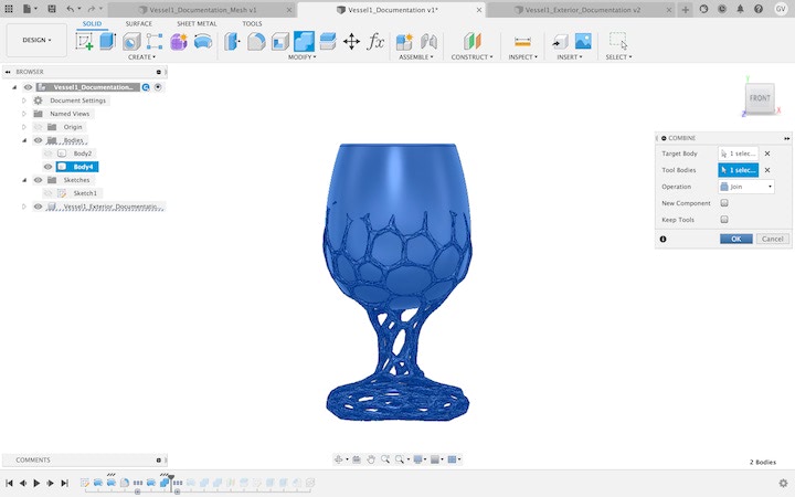
I then used the same tool to combine the modified voronoi body with the upper vessel body by setting the operation to “Join.”
With that, the model was complete! For the sake of improved documentation, I decided to create a rendering of the model. A great way to add some flare to a simple rendering is to model a very basic table beneath the object to give a little contrast and sense of scale.
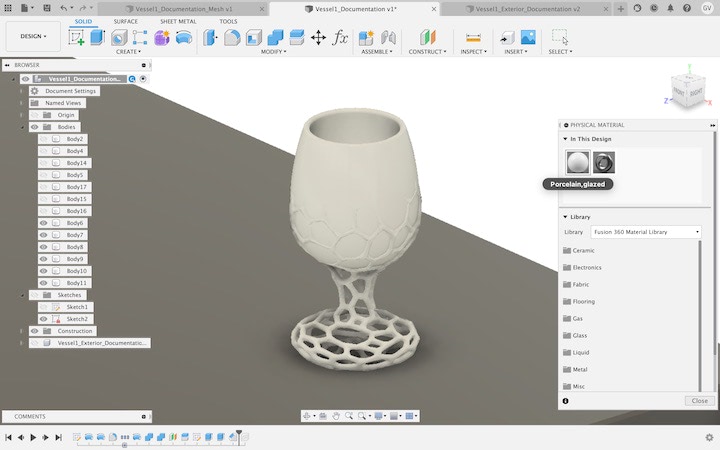
I used the Physical Materials tool to apply the “Glazed Porcelain” material to the drinking vessel, giving the model the appearance it would have if it were to be 3D printed by Kwambio.
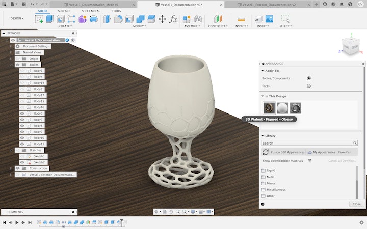
I also used the Appearance tool to apply the “3D Walnut - Figured - Glossy” appearance to the table. While there is a category of “Wood” appearances that cover each face in an identical wood grain pattern, I highly recommend using the “3D Wood” category of appearances that have a three-dimensional grain that give the model the appearance of being carved from one piece of wood. Once the appearance was applied, I entered the Render workspace, and selected the “Scene Settings” menu from the toolbar.
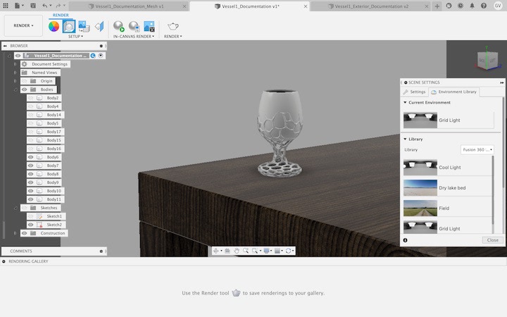
After I found lighting settings that looked good with my model, I clicked the “In-Canvas Render” button on the toolbar.

While the render looks decent after a couple minutes, it will look much better if you let it run for fifteen to twenty minutes. This is a very computing-intensive process if you don’t have a dedicated GPU, so if you’re using a laptop I suggest closing every other application while you’re performing in-canvas rendering in Fusion 360.
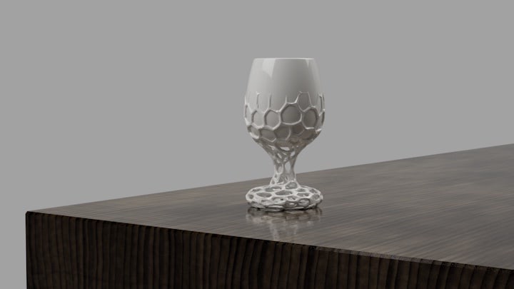
This finished render tells much more of a story than a screenshot of the CAD model, which will improve the quality of feedback I can receive from sharing it, and ultimately help achieve a finished design more quickly. While there are definitely things that I would change about the current design, I feel that it is a very good starting point, and I’m excited to see how the development process continues.