Week 4: Electronics Production
I was pretty excited at the beginning of this week, as I was entering uncharted territory. While I’ve worked extensively with other CNC machines in the past, in the form of 3D printers and laser cutters, I’ve never used a CNC milling or routing machine before. There’s something more intimidating about subtractive manufacturing, as you start with something pristine, and your job is to destroy it just the right amount.
Feb 17
The lecture served as a general overview of manufacturing and soldering circuit boards, but I still felt fairly unclear about what our goal was, and how we would go about accomplishing it. After Neil finished calling on students via the random name generator, I volunteered to share my experience throughout week 3. I was excited to do this in order to share my experience with designing the 3018 CNC enclosure during Week 3, and to see if any other students were working on similar projects.
Feb 18
Spencer and Luciano did a great job of explaining the what, why, and how of this week’s assignment. There were several programmers highlighted during Neil’s lecture, but Spencer suggested that we start by milling the SAMD11C14 UART/UPDI programmer. We would load the .png files into the Mods, where we can determine our speeds & feeds and other settings, then export the g-code file to Universal G-Code Sender (UGS), which will let us visualize the g-code, manually control the CNC mill, set our “zero” position, and start the milling operation.
Our home kits came with four types of milling bits: ten 20-degree “v” bits, ten generic 1/64” end mills, two Carbi-Universal 1/64” 2-fluted, square-end, AlTiN-plated end mills, and ten generic 1/32” end mills. The v bits and 1/64” end mills were intended to be used to cut the traces of the PCBs, and the 1/32” end mills were meant for cutting the perimeters. Spencer said that the v bits don’t provide the same level of quality that the square-end end mills do, but they are cheaper and sturdier, so it’s a good idea to a hang of the workflow with the v bits before switching to the 1/64” end mills.

To do this testing, there is a file on the CBA website that consists of an array of lines of varying thickness, ranging from 0.001” (one thousandth of an inch, or “thou”) to 0.020”. Cutting this file will quickly provide an indication of what level of detail is capable with the given tool and settings.
One of the most important steps of the entire process is setting an accurate “zero” position for the tool to start the milling operation. While alignment in the XY plane can be achieved relatively easily, Z axis alignment is much more difficult, and much more important to the success of the milling operation. Spencer described a process where he uses the manual “jog” controls in UGS to lower the tool until it is in contact with a piece of paper laying flat on top of the PCB blank. He then removes the paper and measures it with calipers, then sets the “z-axis step size” equal to the thickness of the piece of paper, and lowers by one step. This insures that the tool is as close to the surface of the PCB blank as possible without plunging into it and breaking.
Feb 19
My classmate, Nick Anastasia, was able to start milling his PCBs on Friday. He shared his successes and failures in our node’s WhatsApp chat, and I compiled the settings he used, along with the insights from our TA, Spencer, into a spreadsheet to document what worked, and what didn’t. This was a very useful tool for me, as I was able to easily analyze individual factors across all tests, which informed my settings before I even began to test with my own router.
Feb 20
Once the I had downloaded the “traces” and “outline” .png files for the UART/UPDI connector, it was time to open them in Mods. I right clicked to open the menu, click “programs,” “open program,” and select “mill 2D PCB” in the G-code section.
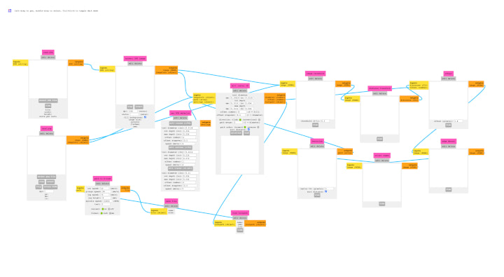
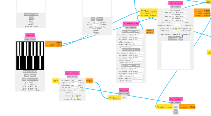
The modular nature of the program makes the user interface appear fairly cluttered on first glance, but it is fairly easy to work with once you get the hang of it. First, we’ll upload a .png file into the “read png” module in the lower left.

Once the file is open, we can set the parameters for the milling operation. Moving forward, we can disregard the modules on the right of the screen, focusing on the “path to g-code,” “set PCB defaults,” and “mill raster 2D” modules. Once we set the cut speed, plunge speed, jog height, and spindle speed, we can either choose tools settings from one of the defaults in the “set PCB defaults” module or use the “mill raster 2D” module to manually set the tool diameter, cut depth, max depth, offset number, and offset step over.
Once all these settings were determined, I pressed the “calculate” button in the “mill raster 2D” module to generate the tool paths.

Once Mods generated the .nc file, I changed its name to include the feed rate, plunge rate, and cutting depth, so I could easily identify it next to other files with different cutting settings. I also opened the file in TextEditor, removed the “T1M06” command from the code, and saved the file.

I’m not exactly sure what this g-code command does, but Spencer informed is that we would get an error in UGS if we didn’t remove it.
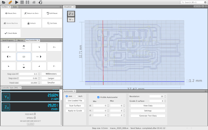
I then opened UGS. The file icon in the top left allows you to open the .nc file you’d like to mill. While you can visualize the tool paths in the “visualizer” window, much of the UI is greyed out until you connect your computer to the CNC router.

In order to do this, you must plug the USB cable attached to the touter’s main board to your computer, select the correct USB port at the top of the UGS window, select the appropriate firmware (GRBL, for my router), select the appropriate baud rate (115200), then press the plug icon to connect your computer to the router. Once the router is properly connected, you will be able to interact with the Toolbox and Jog Controller, and the Controller State (DRO) and Console will populate with information.
Once the file was uploaded to UGS and the CNC router was connected to the computer, I had to set the “zero” position, which serves as a reference point in three-dimensional space for the origin of the milling operation. In order to determine this location, I fixed my copper-clad FR1 board to the router’s “waste board” with double-sided tape, and used the “jog” controls in UGS to position the cutting tool (the 20-degree v bit) in the lower left corner of the area I wanted to mill. While it is relatively simple to set the origin in the X and Y axes, setting the origin in the Z axis requires more precision. For the router to cut the material at the proper depth, the Z axis coordinate of the “zero” position must be precisely on the surface of the material. If this position is too high, the tool will not cut deep enough into the material. If the position is too low, the tool will crash into the material and break.
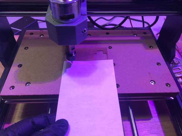
I set the zero position by jogging the z axis down so the tip of the cutting tool was about 1 mm above the surface of the material. I then placed a piece of paper on top of the material and turned the “step size” down to 0.05 mm so each click of the “-Z” button in the jog controller only lowered the Z axis 0.05mm. I moved around the paper as I clicked the -Z button until I could feel that the cutting tool was in contact with the paper. I then removed the paper, used my calipers to measure its thickness, set the step size equal to the thickness (0.06mm), and clicked “-Z” in the jog controller so the nozzle was almost perfectly in contact with the surface of the FR1 material. Finally, I pressed “Reset Zero” to set the tool’s current location as the zero position for the cutting operation.
The first file I attempted to cut was the line test file with the 20-degree v bit. The standard “2D PCB” Mods program does not include a tool profile for a v bit, but Spencer reported that he had reasonable success with the 1/64” end mill profile. Jacopo Di Matteo did develop a Mods module for v bits, but his results weren’t perfect. I adjusted the default cutting speed to 45 mm/min and the default plunge speed to 30 mm/min. The file took about 45 minutes to cut.
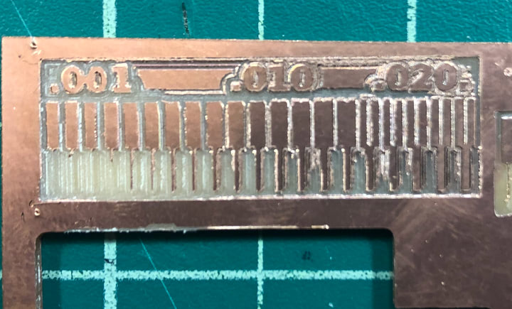
As you can see, there are two things going on here. First, the thinnest trace that was preserved was the fifth from the left, the 0.05”. If our design has traces thinner than 0.05”, they would not be preserved if it was cut with the current tool and settings. Second, some of the copper layer was not fully milled away on the right side of the design. This is due to curvature on the surface of the board: the right side of the board was lower in the z axis relative to the cutting tool.
While the line test file is very useful, it took a decent amount of time to fully cut. To distill the essence of the test, I used GIMP to isolate the 0.005”, 0.010”, 0.015”, and 0.20” traces to get a file that could help characterize my cutting tools and dial in settings in a fraction of the time.

I imported this file into Mods and began to dial in the settings for my 1/64” end mills. With the default cutting speed and plunging speed, the first bit snapped immediately. I cut both of these values in half and was able to successfully cut my modified test file. I used these same settings to cut out this modified test file with the Carbi-Universal 1/64” end mill. While these bits were able to cut twice as fast as generic 1/64” bits, I unfortunately broke both of my Carbi-Universal bits, so I was forced to use the generic bits to continue with my experimentation.
The first of my Carbi-Univeral bits broke when accidentally jogging my CNC mill in the X-Y plane after I stopped in the middle of a cutting operation. This meant that the bit was already beneath the surface of the material, so the bit snapped when it ran into the material. The second of my Carbi-Universal bit broke when I was attempting to zero the z-axis. I was holding down the “-Z” button in the jog controller, and when I let go, the axis came to a full stop before it began to move in the same direction without any input. As the bit was only a few millimeters above the material when I let go of the jog controller, I didn’t have enough time to reach the “stop” button before the bit crashed into the surface of the FR1 board. I’m unsure whether this issue stemmed from my computer or UGS, but it has happened when jogging the router in other axes as well. While this can happen in other directions without much risk to the machine, if this happens in the -Z direction, there is a large possibility that expensive bits can be destroyed.
While I continued to push on with the less resilient, generic bits, I ordered some more high quality bits so I could push the limits of my machine in the future. I ordered two of the Carbi-Universal 1/64” 2-fluted, square-end, AlTiN-plated end mills, and two PreciseBits 0.0150” Tapered-stub end-mill at the suggestion of Daniel Meyer. Daniel’s documentation goes into depth characterizing these bits, and on minimizing runout with desktop CNCs, which is a large factor that mitigates the quality of the results they can produce. He also discusses calculations he used to determine the “speeds and feeds” of this bit, which are very helpful to know, but I felt like I was in a bit over my head. I rewatched a video on the subject on Winston Moy’s YouTube Channel, which was very helpful in getting me up to speed on the topic.
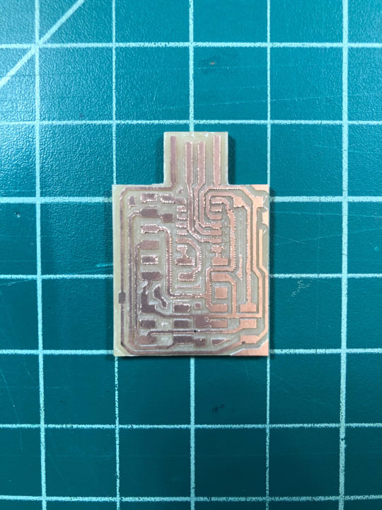
While I was waiting for these new bits to arrive, I milled out the traces of the programmer using the cutting settings that I had previously determined to be best for the generic 1/64” end mills. This job took about four hours, but was ultimately without incident. I then used the 1/32” end mill to cut out the perimeter of the board. While this also went well, this was actually the first time I had cut with the 1/32” bit, and it would have been a smart decision to characterize this bit before using it on a job that was already four hours in, rather than just using the default settings and crossing my fingers. Once I removed this part from the waste board, I noticed a major flaw: the trace operation and the perimeter operation were out of alignment, so the USB port on the board was off-center, and wouldn’t function properly. I realized that this was due to the fact that I rotated both of these files 90 degrees clockwise in UGS in order to have the design fit on the material, without having to remove it from the waste board and manually reposition it. This was frustrating, but it was a good lesson to learn on a relatively low-stakes part. Thanks to the suggestion of Spencer, I was able to salvage this part with an X-acto knife and a steady hand.
Feb 21
Still frustrated with my last experience with the generic bits, I ran some more small scale tests to see how hard I could push them before they meet their eventual demise. The first test ran at 15 mm/min cutting speed, and 15 mm/min plunging speed. I noticed that the heaviest vibrations occurred during the plunging, with relatively minimal “chatter” during the cutting, so I ran the next two tests at progressively faster cutting speeds, and progressively slower plunging speeds. The YouTube channel “Breaking Taps” posted a great video showing end mill chatter in slow-motion.
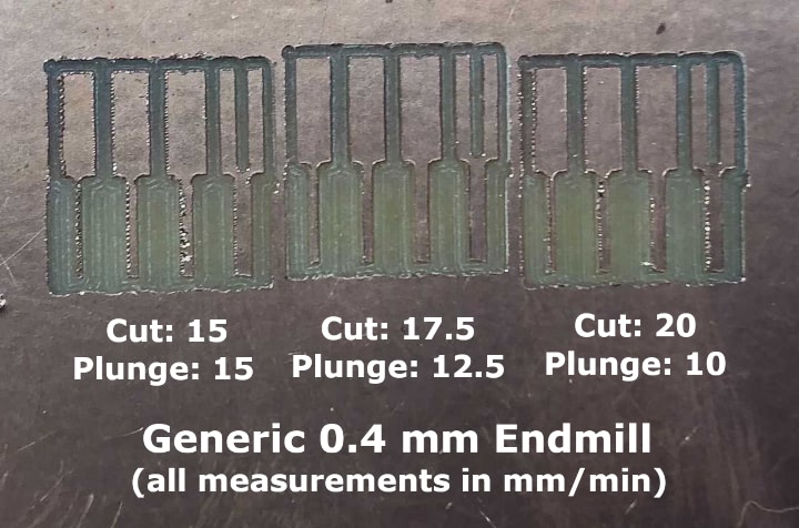
This picture shows the results of the three tests. I then attempted to cut the UDPI programmer using the plunge speed that resulted in the lowest chatter, and the cutting speed that resulted in the least burring. Unfortunately, due to the waste board not being perfectly level, the endmill did not cut entirely through the copper layer on the corner of the design that was farthest away from the origin of the design, where the tool was zeroed. In an attempt to salvage the part, I increased the depth of cut, but this resulted in two endmills breaking, and I abandoned the job. While this problem could have been saved by the autolevelling module in UGS, I received a disheartening error message when attempting to use the feature. Adrian’s CNC Home Lab documentation discusses using an autolevelling feature in the Candle software, and Nick Anastasia sent me the link to a Github issue page detailing how to set up Candle on Mac OSX. The lack of ability to autolevel, plus the issue I described previously with the jogging controller, are large enough issues that I will probably switch to another g-code sender moving forward, and Candle seems like the best candidate so far.
Feb 23
The high-quality end mills arrived, and it was time to put them to the test. I ran some more small scale tests based on some previous experiments Nick had performed, and I pushed the Carbi-Universal end mill all the way up to 150 mm/min cutting speed, but kept the plunging speed at 25 mm/min throughout all three tests.
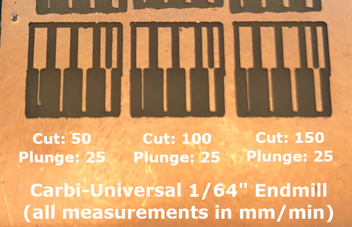
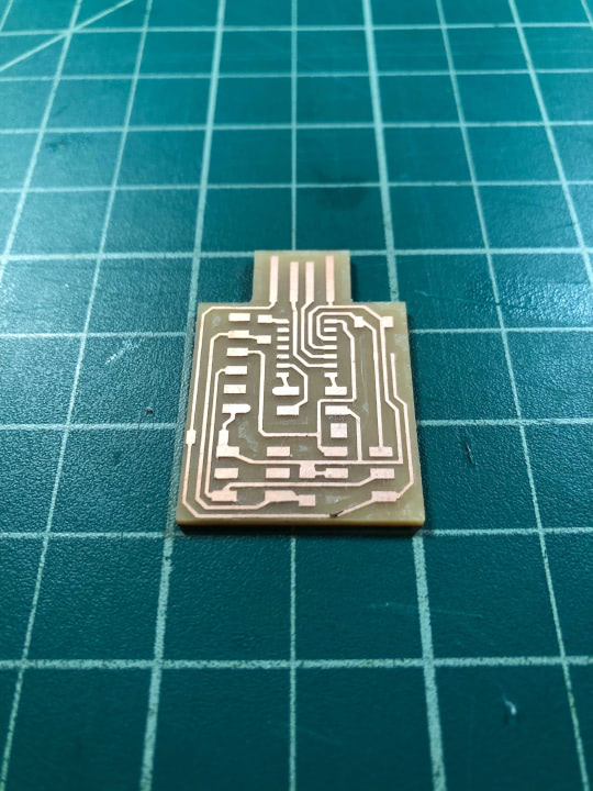
This picture shows the results of the tests. Even though the highest speed tests had zero burring, I decided to be slightly conservative, milling out the UDPI programmer at 100 mm/min cutting speed and 25 mm/min plunging speed. The trace milling operation and the perimeter cutting operation were finished in a combined 28 minutes and 26 seconds, and turned out beautifully.
Feb 24
I do have a fair amount of experience soldering SMD components on professionally produced circuit boards, but I have never soldered them onto a milled FR1 board. The main difference with these boards is that the board I milled has no solder mask, meaning the traces are exposed and potentially have a greater chance to bridge if I’m not careful when soldering, and that the copper is potentially more likely to delaminate from the substrate during desoldering.
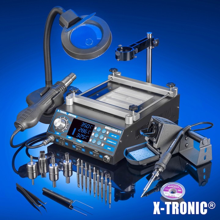
To solder the UDPI programmer, I used the X-Tronic 5000 soldering station that I use for all of the soldering work I do for Traintrackr. There are a couple less standard tools that I swear by, pictured below.
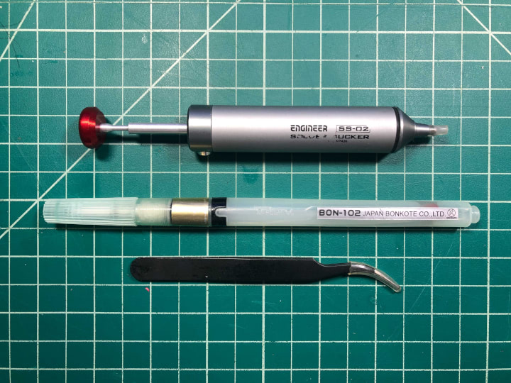
The first is the Engineer SS-02 Solder Sucker. This solder sucker is lightyears ahead of generic solder suckers, partly because of its all-metal body, but mainly because of its replaceable silicone tip which allows you to get right on top of SMD components in tight places to form a solid seal, and get your soldering iron against the tip of the sucker without melting it. The other tool I love is the Bonkote 102 Flux Pen. This pen has a refillable reservoir and a fine-point brush tip, which allows you to get into much tighter spaces than the larger-tipped flux pens can fit.
While Quentin Bolsee’s original post I was referencing during assembly of the SAMD11C14 UART/UPDI programmer had no BOM, Nick included a BOM in his Week 4 Documentation. One issue that I did have was determining the orientation of the ATSAMD11C14 IC. Many ICs I’ve worked with in the past have a much more noticeable small circle to match with a small circle on the circuit diagram, but it took me a while to identify the circle in the schematic or on the IC. Once I identified these, I was able to match them up and solder the ATSAMD11C14 in the proper orientation.
One technique that was very helpful during the soldering process was wetting the first pad with solder before the component was on the board, so I could easily tack it down while holding the tweezers in one hand and the iron in my right hand. I used this technique for pretty much every component on the board that had more than two pads. With this, my programmer was finished, and I could move on to testing it.
Quentin’s documentation detailed using the Particle Debugger, which I borrowed from my classmate, Xiaolin. I referenced the Particle Argon datasheet to find the pinout from the header, and referenced Quentin’s documentation to match it to the JTAG headers.
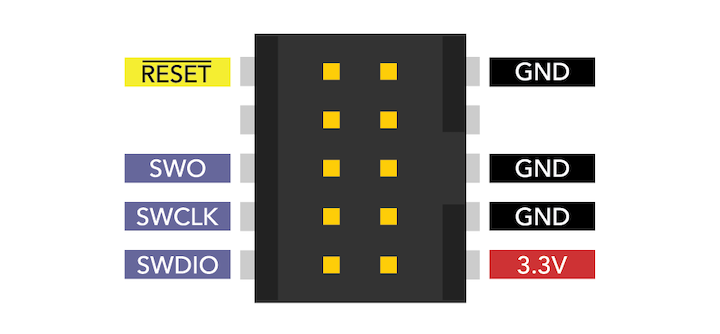
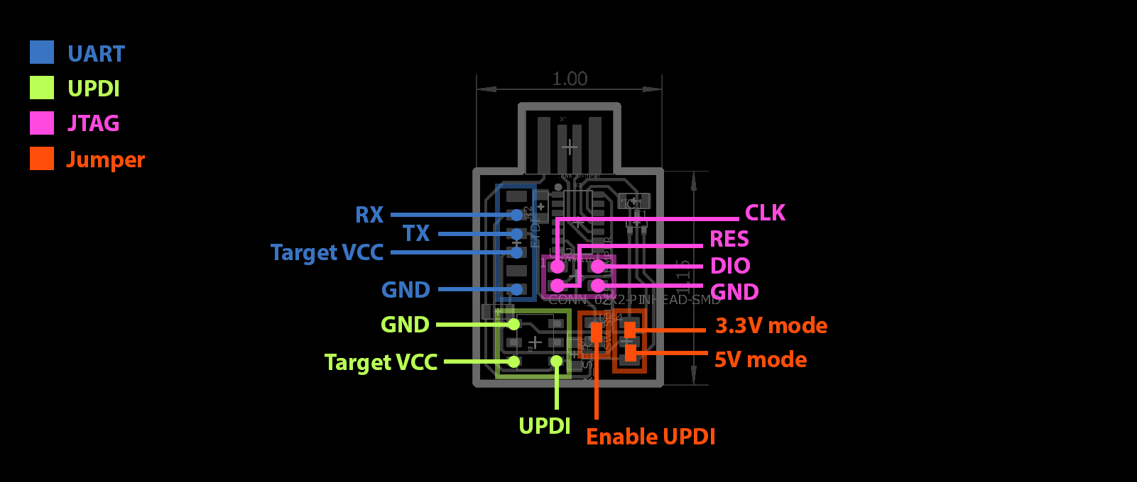
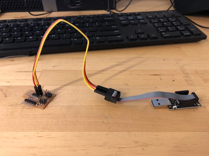
With the pinout files documented, I was able to connect the JTAG programmer to the Particle Debugger using the included connector cable and some jumper wires.
I then downloaded the .bin file listed by Quentin and a release of EDBG that can run on Mac OSX. Reading the EDBG readme file, I saw that I needed the hidapi library, but was unable to get it up and running. I referenced this article that suggested I run a command to install Homebrew, but I couldn’t get it to install.
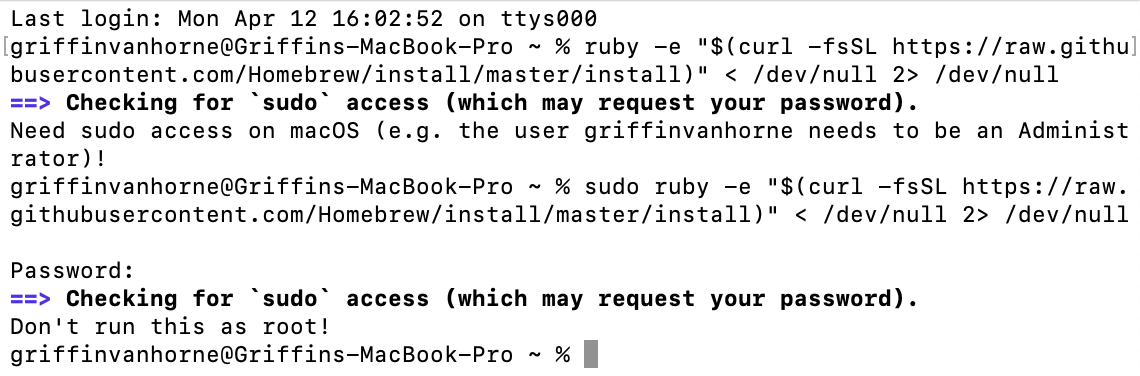
I tried downloading Homebrew directly, but couldn’t get that to run either. At this point, I shifted my efforts to using the J-Link EDU Mini debugger. I referenced Maryam Ali’s documentation, which seemed fairly straightforward, but required Atmel Studio 7, which can only run on Windows.
Jun 20
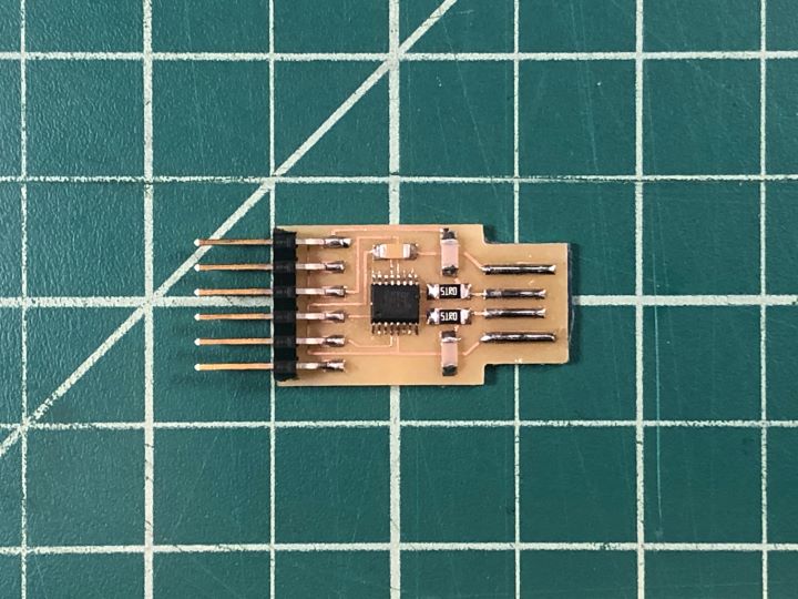
It was finally time to revisit this assignment, as everything else was complete. I changed tactics, this time creating an FTDI programmer with the FT230XS chip. I used Neil’s [Embedded Programming week documentation], downloading the trace and “interior” files, and referenced the annotated schematic and completed board image.
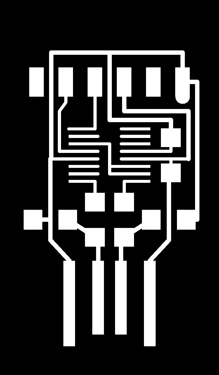
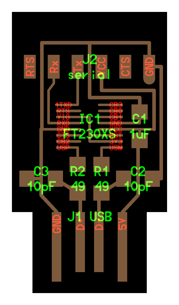
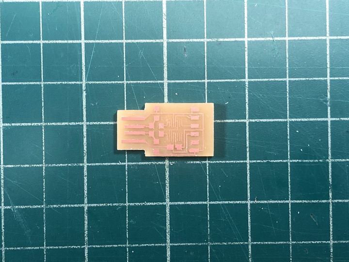
First, I imported the board files to Mods, then used the same parameters that I detail elsewhere in my documentation to generate the g-code. I imported this g-code to UGS and milled out the board on my 3018 PCB mill.
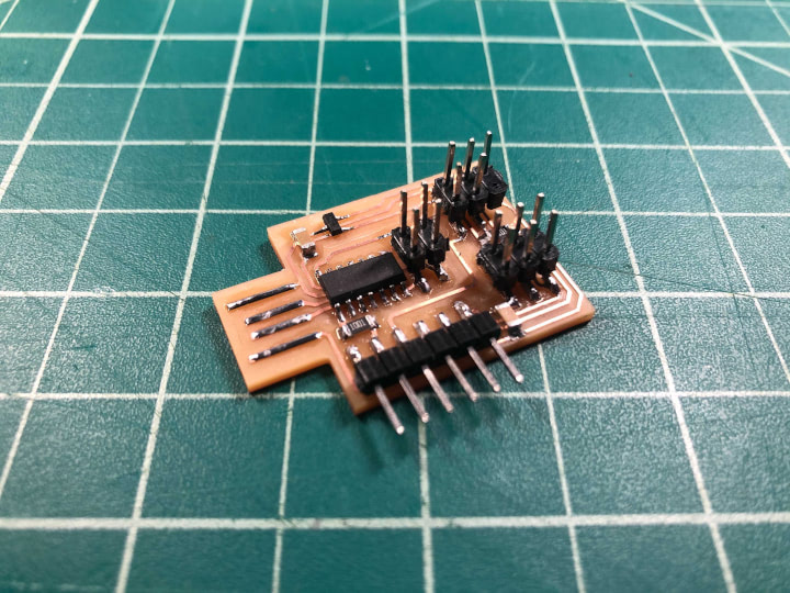
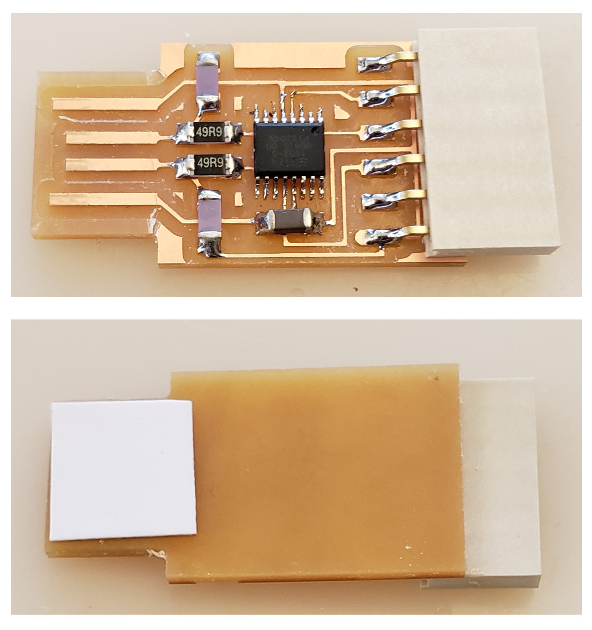
The traces for the FT230XS chip were very thin, and the pitch was small, so this took a couple of attempts to get a functional board. In the future, it could be interesting to experiment with using multiple end mills with different diameters to cut out different traces on the same board. Once I had a fully intact board, I then soldered all of the components. As the pitch between the pads is very small, I did experience some bridging between pins. I found success with using the soldering iron to heat up one of the pads, then gently sliding an X-acto knife between the pads until the solder cools.
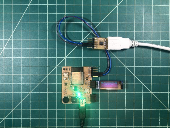
I noticed that when I attempted to power the ESP32 board using the FTDI programmer, the power indicator LED on the board and the MPU6050 breakout board would turn on, but the RGB LED and the OLED would not turn on. This being the case, I plugged the TX and RX pins from the FTDI programmer into the EPS32 board with jumper wires, and powered the board with the Mini USB cable.
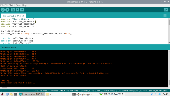
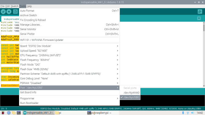
With the board powered on properly, and the programmer appeared in the list of ports in the Arduino IDE as “USB0.”
I then used the FTDI programmer to program the ESP32 board as I would with any other FTDI programmer, and it worked!
I uploaded the final code used on my final project. For the full code, please see my final project page.