Week 5: 3D Printing & Scanning
This week was slightly disappointing, as I have a lot of experience with 3D printing and was looking to push the envelope, but I became swamped with work from my day job right at the beginning of the week, and unfortunately had to limit my experimentation accordingly.
Feb 24
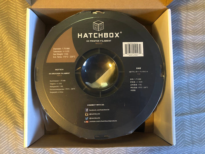
During the lecture, I asked Neil if he thought G-code was outdated, and what its successor would be. He essentially said that there wouldn’t be a successor, as the solution is to simply bypass G-code, and have the computer performing the slicing directly network with the printer. I also informed the chat that I would giving a brief talk on the current state and future trajectory of FDM 3D printing on Tuesday, 3/2, as part of the Cambridge Hackspace Virtual Project Night. Neil asked if I had worked with wooden filament, which I had not. I hadn’t seen Neil excited about something in that way before, so I promptly ordered some Hatchbox Wood PLA filament.
Feb 26
The wood filament arrived, and it was time to test it out.
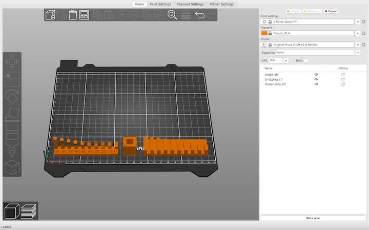
I downloaded some of the test “coupon” .stl files from the 3D Scanning and Printing page on the Fab Academy site. I opened these files up in PrusaSlicer, set the filament profile to Generic PLA, and set the layer height to 0.15 mm.
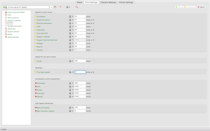
I also went into the Print Setings” tab, clicked the “Speed” option, and changed “First layer speed” from 20 mm/s to 10 mm/s. Lowering the first layer speed minimizes the chance that the first layer will peel away from the build plate, and increases the chances of success.
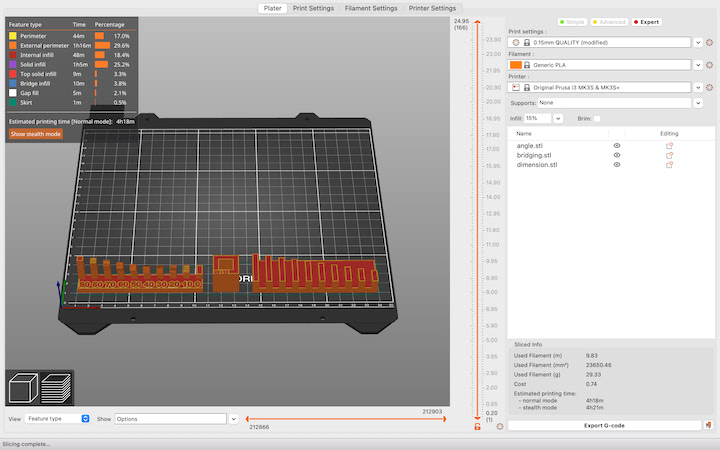
I then went back to the “Plater” tab and pressed “Slice.” Once the model is sliced, a g-code visualizer appears. This shows all of the movements the printer will make. Reviewing this preview is an important step, as small features may not appear in the print with a given nozzle diameter and layer height. For this specific print, I checked to ensure that there were no supports beneath the overhangs on the overhang test coupon. Once I confirmed that this was the case, I clicked “Export G-code” and loaded the resultant file on to a SD card.
I inserted the SD card into my Prusa i3 Mk3, which I have named “Printcess,” and selected the file from the “Print from SD” menu. After about 30 minutes of printing, I noticed that one corner of one of the parts in the print was curling away from the bed.
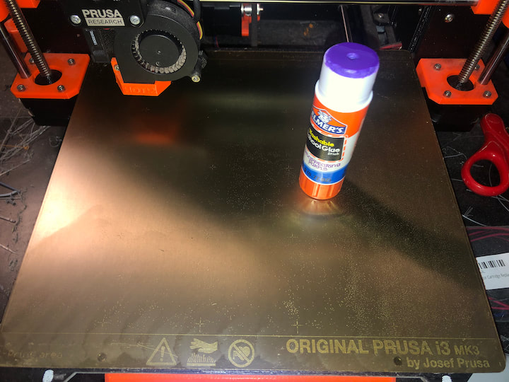
This poor adhesion could be due to a number of reasons, but in this case, I believe it was due to low temperature in the roomI was printing in. I turned on the space heater next to the printer, laid down a layer of Elmer’s glue, and started the print again.
While the print was ultimately successful, there was still some degree of curling in the same corner of the same part. In the future, I’d like to make an enclosure to house the printer to ensure proper ambient temperature throughout the year.
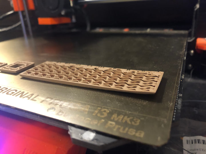
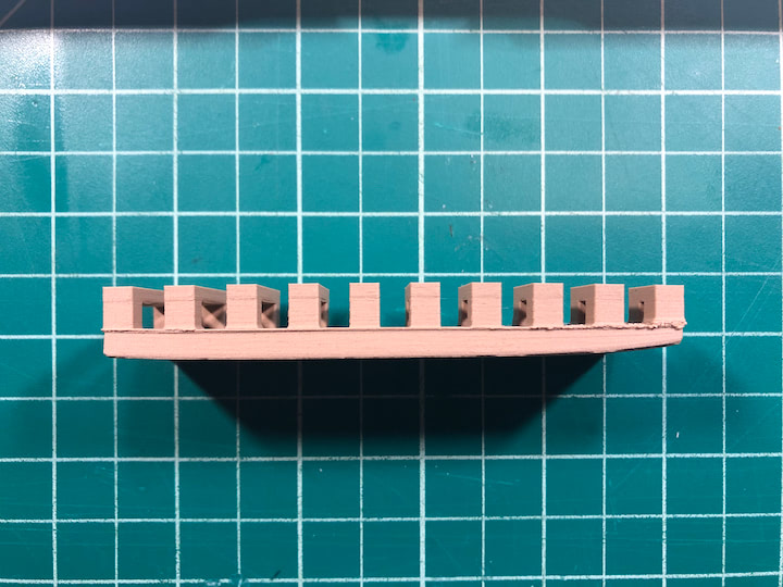
The “bridging” test print demonstrated that Printcess is capable of printing “bridges” in mid-air between two posts up to 20 millimeters apart. This is a helpful test, as it shows that I can print this geometry without supports without worrying about sacrificing quality.
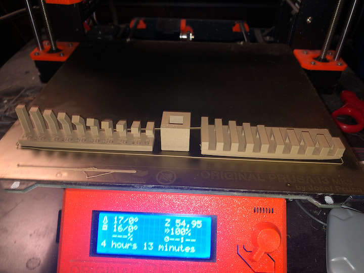
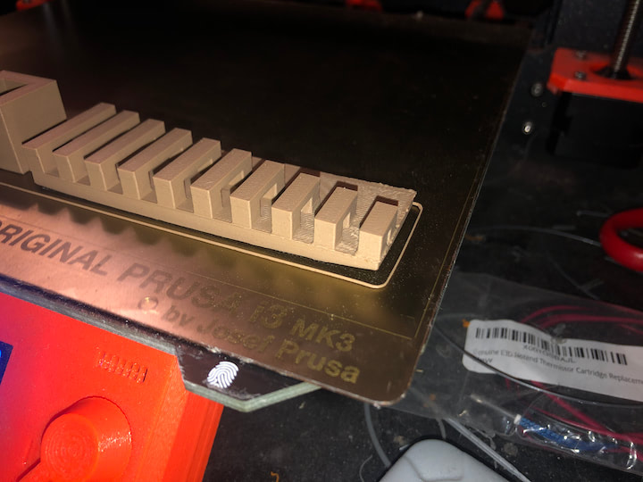
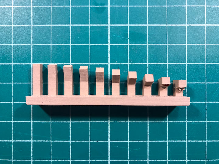
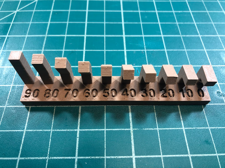
The “overhang” test print demonstrated that Printcess is capable of printing up to 70 degree overhangs without supports. The 80 degree overhang was a little messy, and the 90 degree overhang was very messy. This is also a helpful test, as it demonstrates that I can print steeper overhangs than I previously thought the printer was capable of.
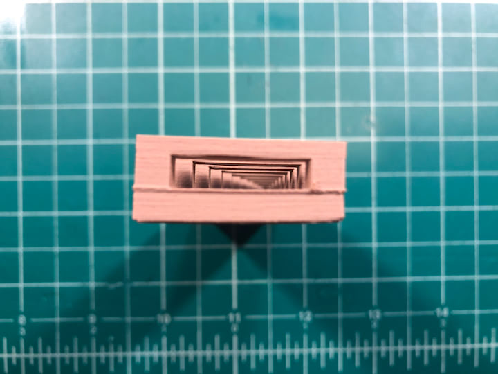
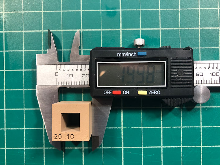
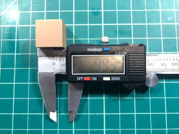
The dimensional test print demonstrated the dimensional accuracy of the printer. FDM printers will have some small degree of over-extrusion that results in parts being slightly larger than intended. This test file had an outside width of 20 mm and an inside width of 10 mm. The actual print had an outside width of ___ mm and an inside width of __ mm. This print demonstrates the exact amount of over-extrusion, and allows me to compensate by including an offset parameter in CAD.
Overall, I would not recommend the Hatchbox Wood PLA. It warps more easily and is more brittle than standard PLA. While the material appears to be wooden in color, its texture and surface finish are indistinguishable from standard PLA. Neil did mention [Fillamentum Timberfill] (https://shop.fillamentum.com/collections/timberfill-filament) by name, but that product was sold out at the time. Looking on their website, Timberfill appears to have a much more grainy surface finish, which has a very interesting aesthetic quality, but I have a feeling that the texture might reduce the consistency of successful prints.
Feb 27
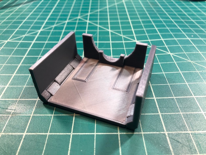
My workstation is in a windowless workshop, so I use a number of bright lights to ensure proper lighting during my video conference calls. One of these lights is directly above my head, which results in some glare in the top of the frame. I usually fashion a make-shift lens hood out of painter’s tape, but I decided to design a print-in-place, adjustable lens hood so I don’t need to waste any more tape.
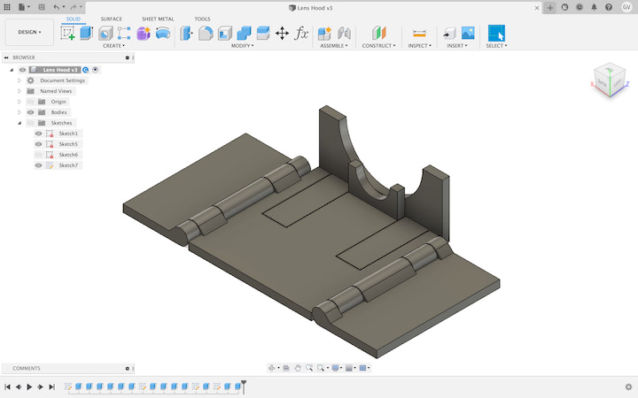
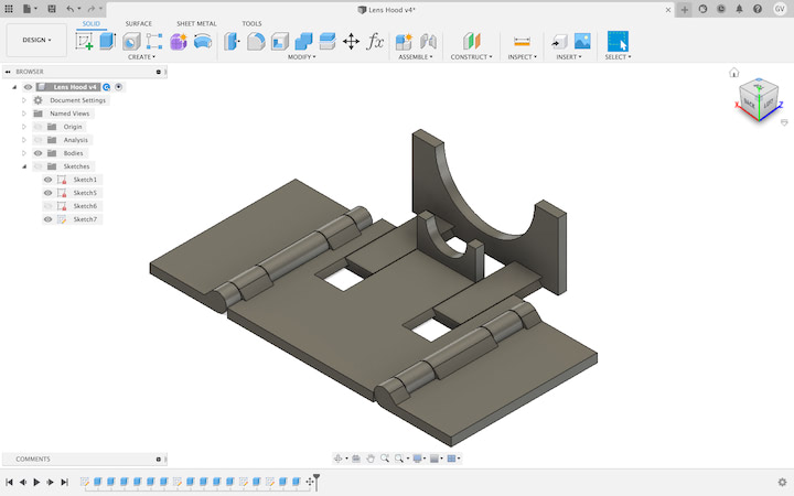
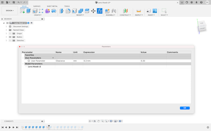
I’ve previously determined that the required offset between print-in-place parts is 0.2 mm. When I created my new CAD model in Fusion 360, I set a parameter, named “Clearance,” to 0.2 mm.
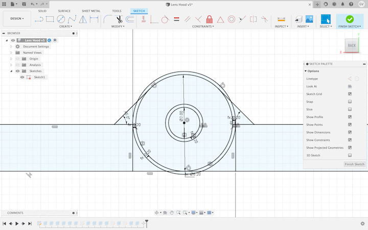
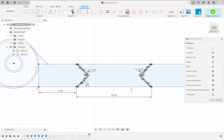
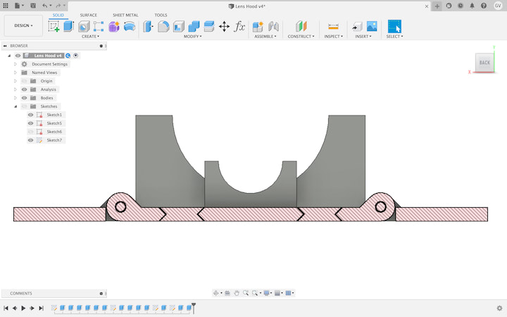
Using this parameter, I designed a lens hood with print-in-place hinges and a sliding mechanism, allowing the lens hood to be printed as one part without requiring any assembly. While the final geometry of the part was relatively complex, the CAD itself was relatively simple, with only two main sketches, and a number of extrusion functions.
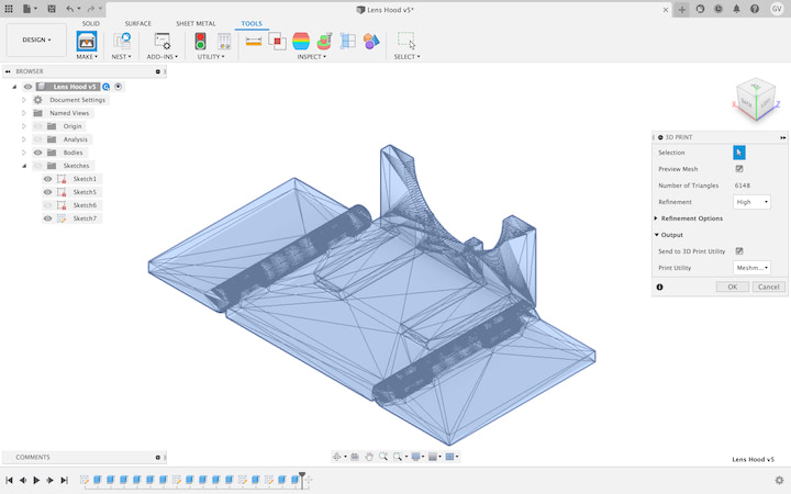
One thing that took a minute to figure out in Fusion 360 is that if you click on the “3D print button” under the “Make” tab, by default you can only export one body per .stl file.
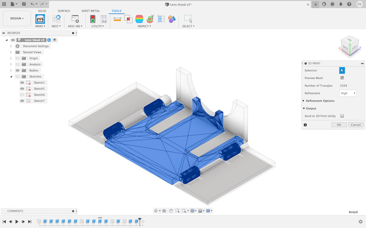
In order to select multiple bodies at once, you must go to the Browser and click on the component that houses all of the bodies you wish to export as the same .stl file. Fusion will show you a preview of the mesh that you’re creating, so it’s easy to confirm that all bodies are properly selected.
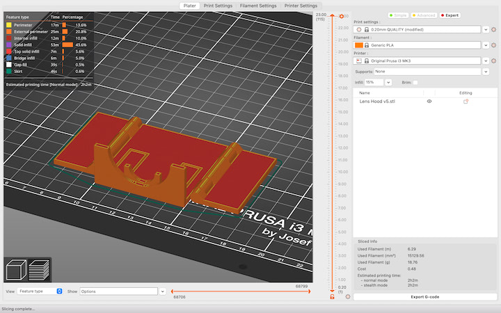
Once exported, I imported the file into PrusaSlicer and followed the same steps to print the file on Printcess.
The print turned out perfect, and the joints and sliding mechanism worked exactly as intended.
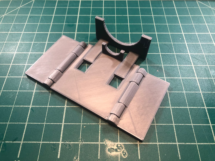
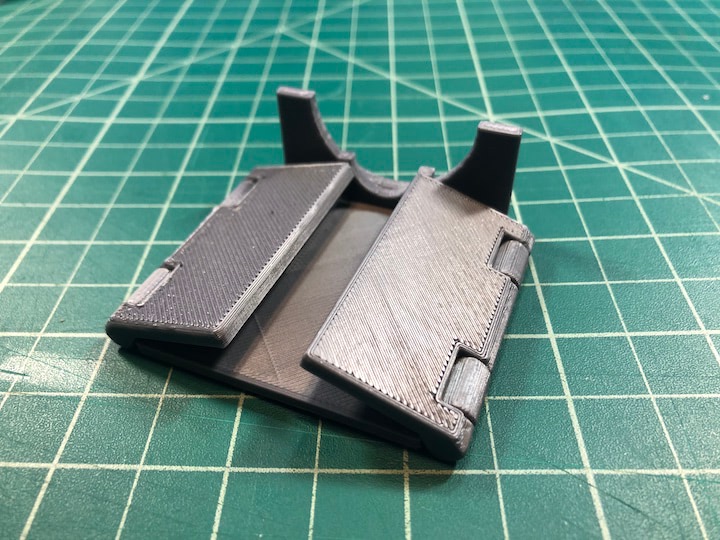
Unfortunately, the design was too front-heavy to function properly as a lens hood. In a future iteration, I would skip the sliding mechanism and put a third hinge on the back face of the hood to make sure it can stay properly attached to my laptop.
Lens Hood Files:
Mar 1
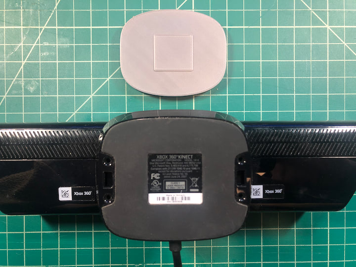
In order to use the Xbox Kinect I had laying around to do 3D scanning, I needed to order a special adapter. The Kinect has a proprietary connector, and the adapter allows to you plug the device into AC power and a USB port simultaneously.
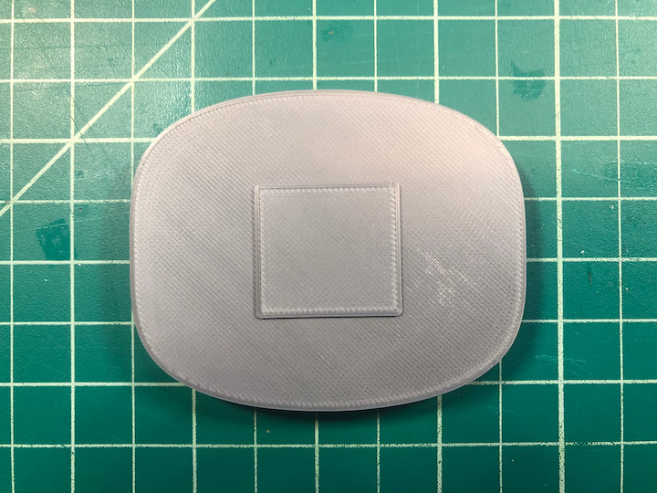
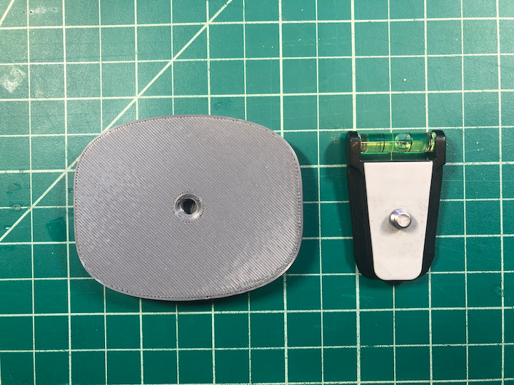
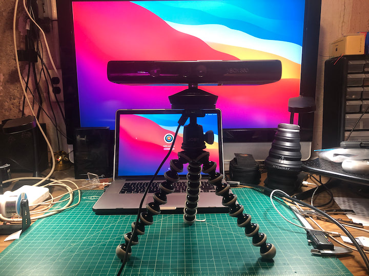
I also designed and printed an adapter to attach the Kinect to a tripod. To do this, I simply traced the base on the Kinect onto a piece of paper, then measured the traced sketch, and used the spline tool in Fusion 360 to replicate the shape. I then measure the length of the bolt on the tripod and extruded the sketch far enough so the adapter could fully contain the bolt with room for a wall above the threaded hole. I then printed out this adapter in PLA, attached it to the Kinect with double-sided tape, and screwed the tripod’s bolt into the adapter.
Kinect Tripod Adapter Files
Mar 1 Cont.
Once the Kinect was mounted to the tripod, I downloaded and opened Skanect. When you first open the program, you will be on the “Prepare” page.
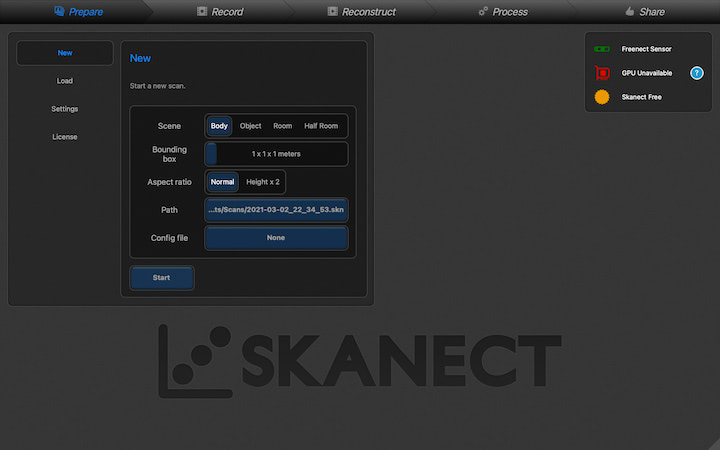
If the Kinect is properly connected, a green sensor icon and “Freenect Sensor” will appear in the top right of the UI. The “New” tab is opened by default, so to continue to the “Record” page, all you have to do is press “Start” in the “New” panel.
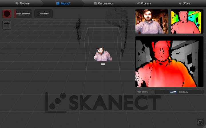
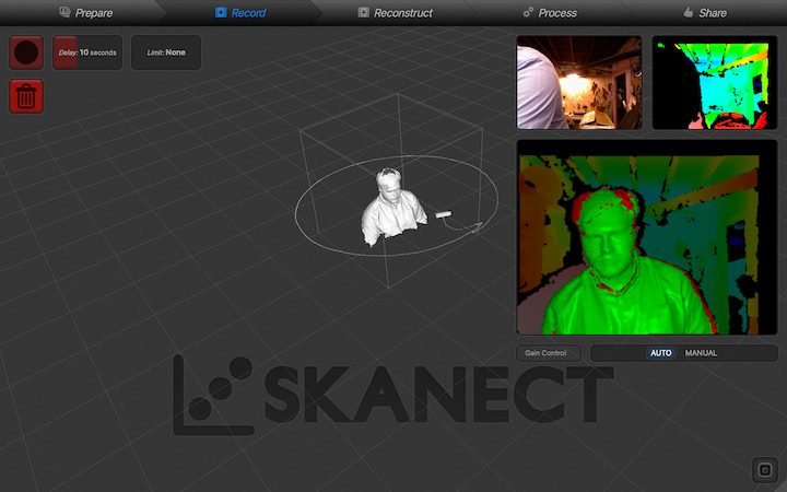
In the “Record” page, you will see three panels on the right side of the screen that show feeds from the three sensors on the Kinect, plus a large panel that shows these live feeds meshed together, to give a preview of what is in the 3D “frame” of the scanner. In the top left, you can select a delay that will give you time to center yourself in the frame after clicking the record button, and you can select a limit to stop the recording after a certain amount of time. I set my delay at 5 seconds, and pressed the “record” button in the top left.
After slowly rotating 360 degrees in my desk chair over the course of approximately 60 seconds, I pressed the space bar to stop the recording. Skanect took a few seconds to process the scan before showing a preview of the 3D mesh created.
I repeated this process a number of times, adjusting the height of the sensor. I noticed that if the sensor was too low, the Kinect would not be able to scan the top of my head. If I placed the sensor too high, it wouldn’t be able to scan beneath my chin. I found that the best results were captured when I placed the Kinect right at eye level, but there were still some gaps in the mesh.
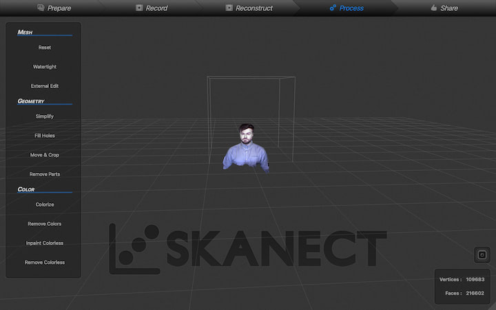
I then bypassed the “Reconstruct” page and clicked on the “Process” tab.
Once on the “Process” page, the first step is to click “Watertight” under the “Mesh” section of the panel on the left of the screen. This will fill all gaps in the mesh to make the model a watertight body. I selected “Medium” smoothing, and clicked “Run”.
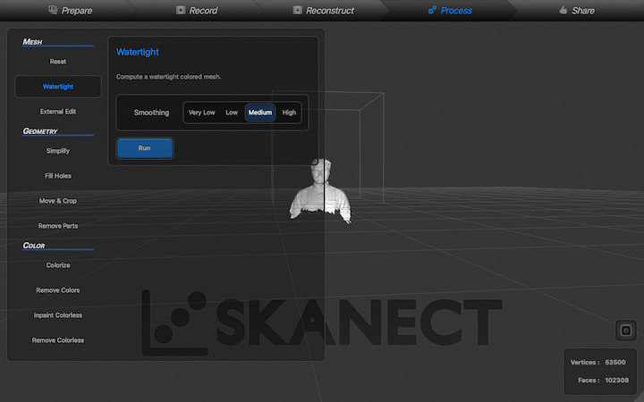
While this function does what it says, it doesn’t do it very well, and left odd geometry beneath my chin and at the top of my head. If I wanted better results, I could have exported the broken mesh to software like Blender or Meshmixer to manually repair the mesh.
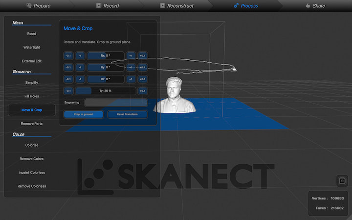
I then clicked “Move & Crop” under the “Geometry” section of the panel on the left, and manually adjusted the “Ty” slider to crop the bottom section of the scan from the model, and clicked “Crop to ground”. This process had the added effect of giving the model a flat base so it could be more easily 3D printed.
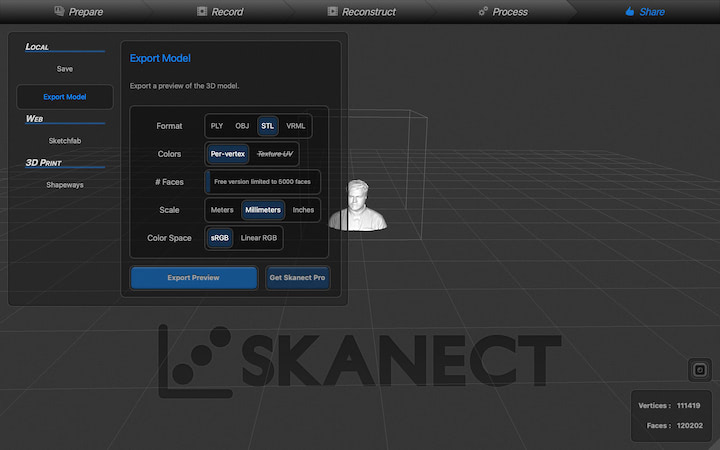
I then clicked on the “Share” tab to export the model. Unfortunately, in the free version of Skanect, you are limited to only 5,000 faces per model. In the lower right of the screen, you can see that this model has 120,202 faces, so exporting this model as an STL will drastically reduce its resolution. I set the file type to “STL,” the scale to millimeters, and clicked “Export Preview.”
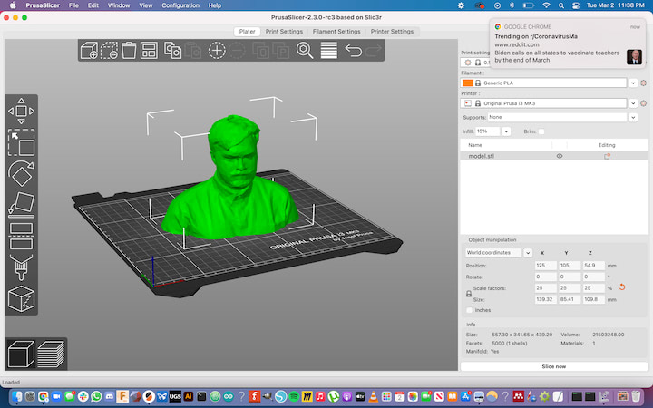
Once the file was exported, I opened it in Prusa Slicer. I scaled it down to 12.5%, lowered the first layer speed to 10 mm/sec, turned on supports “everywhere”, and sliced the file.
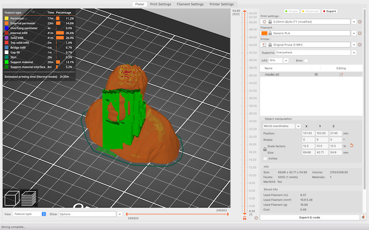
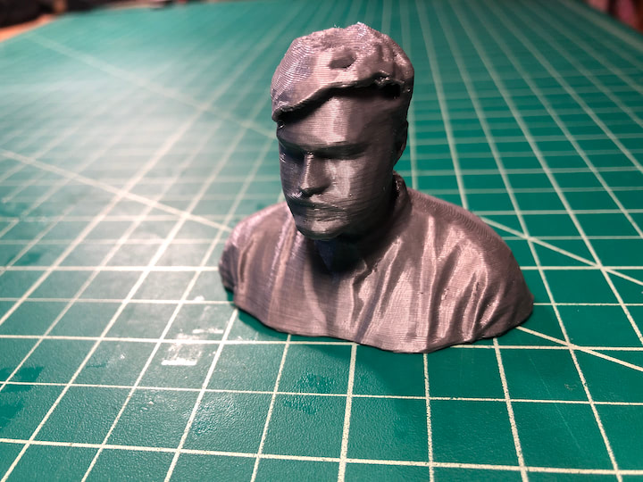
Satisfied with the results, I exported the g-code and 3D printed the model. The results were beautiful.
3D Scan Files
Mar 2
During the COVID-19 pandemic, I have been hosting Cambridge Hackspace Virtual Project Nights through Meetup in lieu of our traditional in-person events. This week, I gave a presentation on the current state and future of FDM 3D printing. I highlighted the history of the RepRap movement, gave a brief 3D printer anatomy lesson, and discussed some new developments in the space. One of the most interesting of these advancements was Klipper firmware’s input shaping capabilities that allow the user to identify and compensate for the resonance of their machine, reducing artifacts that diminish print quality. I also discussed additional sensors that can be incorporated into the printer, such as a filament jam sensor and a filament diameter sensor, closed-loop stepper motors, and The Spaghetti Detective, a print failure detection software. All together, these advancements provide the printer with feedback so it can operate in a much more user-friendly and autonomous way, and can print faster without compromising quality. FDM printing has come a very long way in the past decade, but these recent developments show that this advancement isn’t slowing down any time soon. My slides for this presentation can be found here.