Week 18: Project Development
This is the final push. The success or failure of my final project all comes down to how well I can execute in the next week.
Jun 2
Neil gave a great lecture, and I wish he had given it sooner. All the concepts he touched upon were familiar, but it was still goog to hear him reiterate them. The most important three were Murphy’s Law, supply-side time management, and triaging. Murphy’s Law has been all too real in the past few weeks, and I’m only in a position to finish my project because of how proactive I’ve been with my final project. Nonetheless, I’m still preparing for another problem to rear it’s ugly head, so I’m pushing along to make sure I have time to spare. To account for the other two, I’ll make a list of things I have left to do and a schedule to make sure I have time to get everything done, and cut out what I don’t have time for.
To Do:
Enclosure
-
reduce tolerances on bearing mating surfaces and pill door
-
OLED screen cover
- design screen cover
- design mold
- mill mold
- injection mold part
- adjust enclosure design to accomodate screen cover
-
reprint enclosure in Goo PLA/PHA
PCB
- power management circuit
- redesign main board with power management components and connectors
- mill main board
Code
-
incorporate buzzer
-
remove delays from LED fade
-
adjust hall effect sensor threshold
-
improve OLED code
-
incorporate gyroscope
- read data
- pass threshold
- return to idle state
- send data to app
App
-
incorporate alarm clock
-
include logo and color scheme
Schedule:
Wednesday 6/2
-
Process board files in Illustrator
-
Generate g-code files in Mods
-
Mill boards on 3018
Thursday 6/3
- Solder boards
Friday 6/4
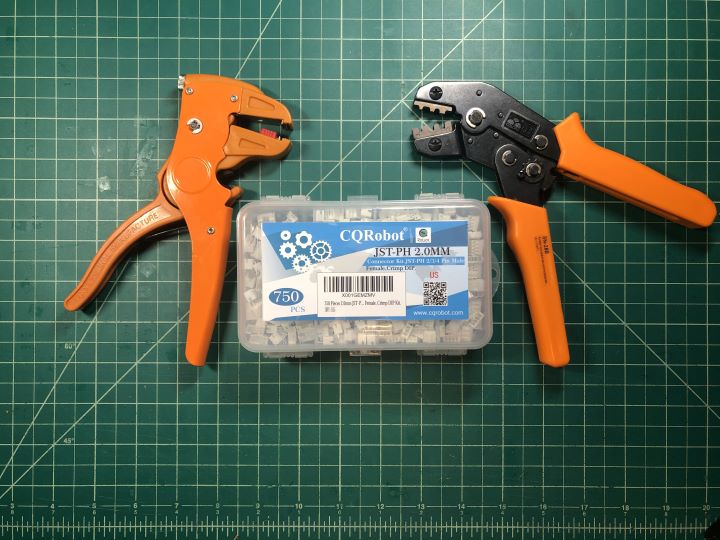
- Attach JST connectors to boards
Saturday 6/5
-
Load code on to board
-
Incorporate alarm clock in to app
Sunday 6/6
-
Incorporate gyroscope data
- film process
-
Design screen cover
- film process
-
Program tool paths
- film process
Monday 6/7
-
Mill OLED screen cover mold
- film process
-
Injection mold screen cover
- film process
-
Begin editing footage
- identify gaps
Tuesday 6/8
-
Integrate power management circuitry
-
re-design circuit board
-
post-process in Illustrator
-
generate g-code in Mods
-
mill board on 3018
-
solder components
-
reprint enclosure
-
film full process
-
Wednesday 6/9
-
Finish integrating power management circuitry
-
Assemble enclosure
- film process
-
Continue editing project video
-
Make project slide
Thursday 6/10
-
Film project functioning
-
Finish editing project video
-
Deep breaths
Friday 6/11
-
Present project video
-
Drink champagne
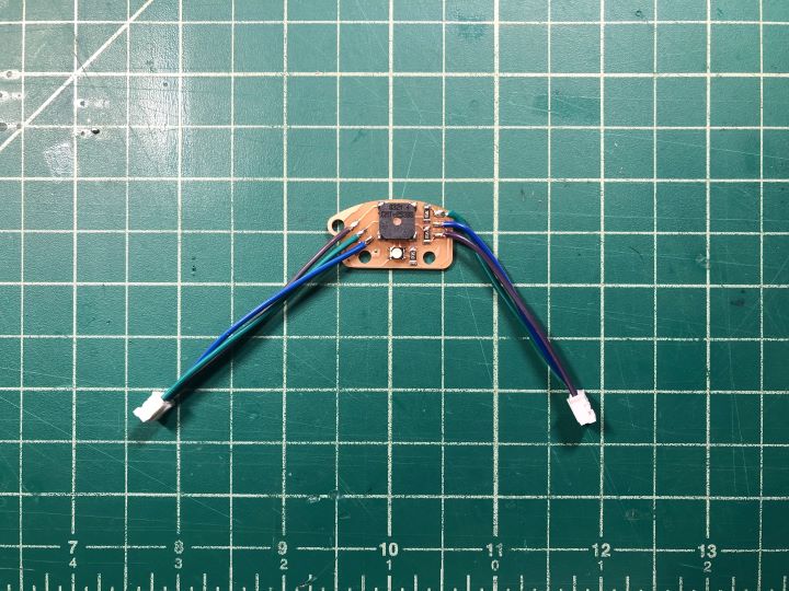
I designed the “feedback” breakout board in Eagle, and generated the “traces” and “perimeter” files in Illustrator.
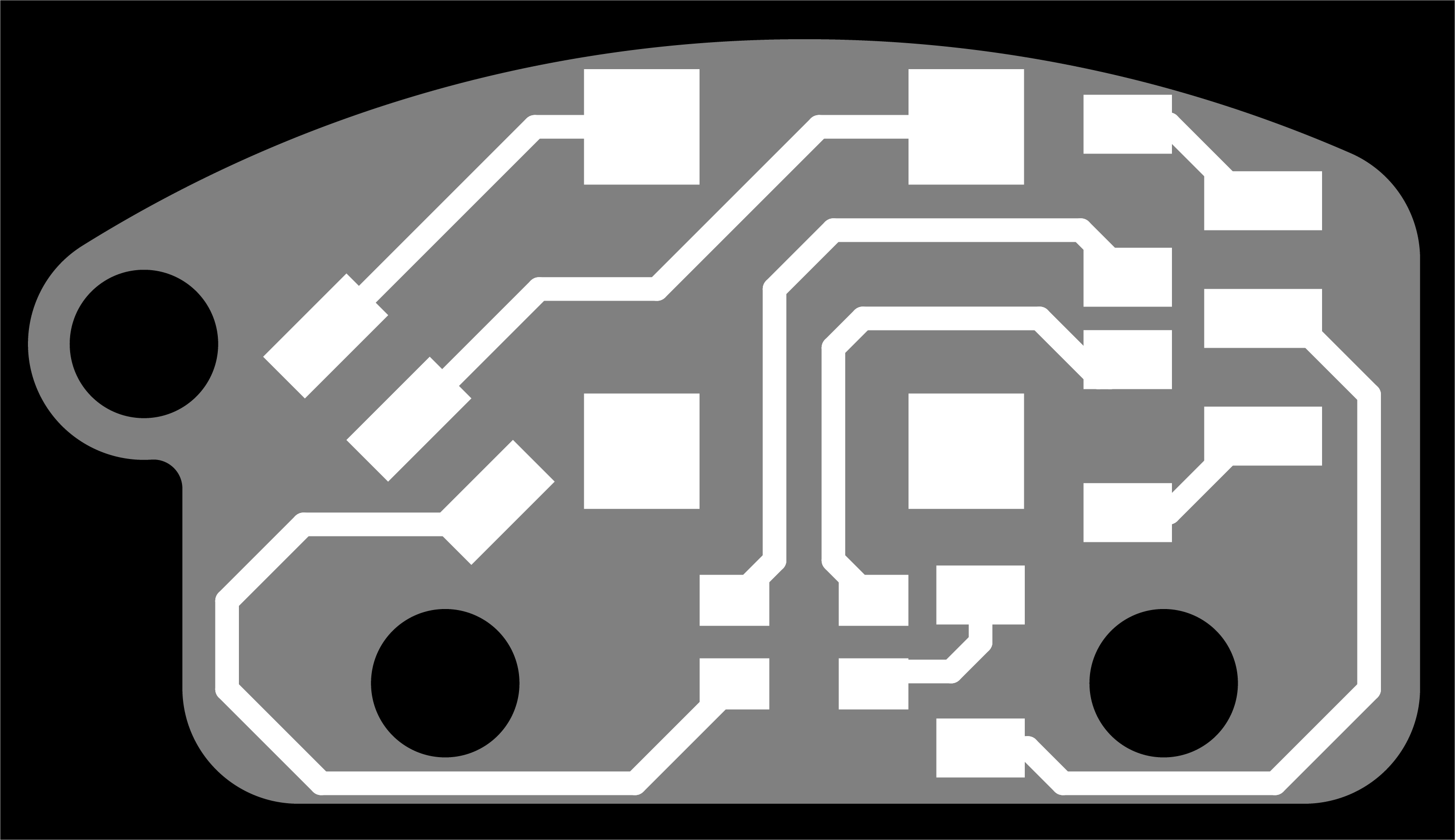


I sent these to Mods and generated the .nc files to send to the 3018. I downloaded Universal G-Code Sender onto my Raspberry Pi 3B+. It ran as I would expect, except for the fact that it didn’t display the g-code visualizer window. It appears as though something changed in Mods, becasue the units were now in mm/s rather than mm/min, which caused me to break two 0.8 mm bits before I realized what was going on. Once I figured this out, I was able to mill out my main board without issue.
Jun 3
Our local node meeting went well, but I was unable to go in person. We talked about triaging and supply-side time management. Greg suggested that of the spirals I could follow once I get everything integrated, I should focus on the power management circuitry and triage the injection-molded screen protector.
After class, I milled the feedback board as well, and began soldering the boards. As I was attempting to film myself soldering, I realized that filming does cause each step of the process to take longer, and I need to adjust my schedule accordingly. I also need to maake a storyboard of my video so I can be sure to get all the footage I need.
Storyboard
-Title slide
-
CAD
-
ECAD
-
Coding
-
3D Printing
-
PCB milling
-
Soldering
-
Flashing
-
Assembly
Jun 4
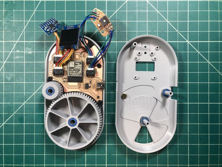
Finally seeing the board populated and integrated into the enclosure was truly a sight for sore eyes.
I spent a good portion of the day wrestling with crimping connectors to attach the breakout boards to the main board. I eventually realized that the crimping tool wasn’t the right one for the job, and I was close to giving up and soldering the boards directly by wires, but eventually I realized that I was also initally positioning the connectors incorrectly, and I was able to position them properly and get the tool to do the job well enough that the wires would fit in the connectors.
Jun 5
I talked during the Global Open Time with Neil, who basically recommended that I scap all new features, and just get what I have in front of me functioning, integrated, and documented. I swallowed my pride, and scrapped the OLED protector and power management circuitry.
This is where seemingly everything went wrong. My beautiful board didn’t program. Continuity and voltage tests with the multimeter indicated that everything should be functioning properly, but the board wouldn’t flash. At one point, I fried the ESP32, and resoldered a new one on to the board, but it still wouldn’t program.
Jun 6
I made slight modifications to the board design, adding back the reset button that I had figured I could remove, because I had been able to program the board with only the flash button in the past. This second board would program, but none of the I2C devices would function properly. I could get the motor to buzz, but that was it. The LED on the IMU module was lit, so I knew it was recieving power, and there was continuity through the JST connectors. Thoroughly frustrated, panic began to sink in.
Jun 7
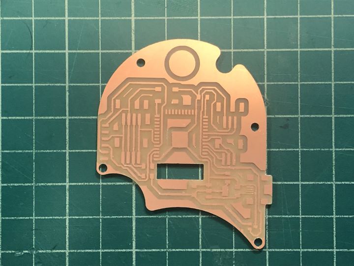
I finally got the files from my crashed laptop back, and I milled out the last board that I had made that had worked without a hitch (see Week 12 documentation). While I had the .png files to mill this board during the “dark ages,” I didn’t have the Eagle files, so I re-designed the two previous failed boards from scratch. Once I got this Week 12 board up and running, I at least felt like I wasn’t going crazy, and I had a new starting point to get a functional board in the right form-factor.
Jun 8
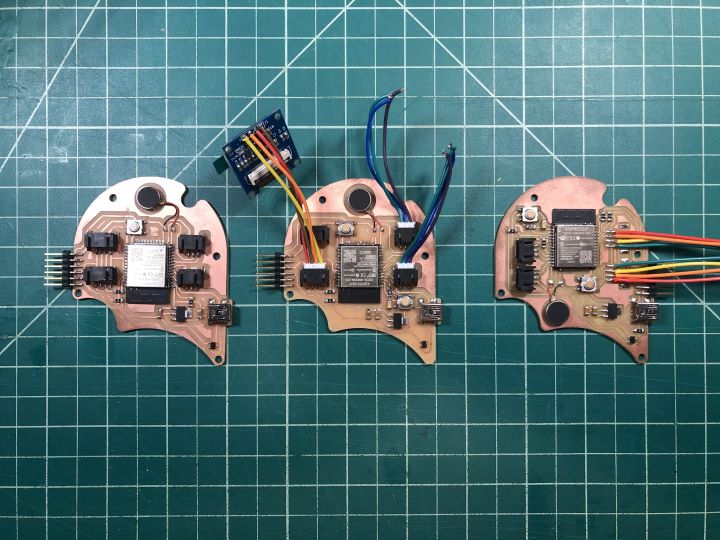
I tried to slightly modify my Week 12 board, keeping the pinout but re-routing all of the wires and adding the SMD JST connectors. This was a mistake, and I had the exact same issue as my second failed board. I had no idea what was causing these issues, and I still don’t. I don’t think it was an issue with the JST connectors, because there was continuity across them, but I should have stopped, desoldered the connectors, and attempted to just solder the wires straight to the board to test this once and for all.
I now had a nice collection of failed boards.
Jun 9
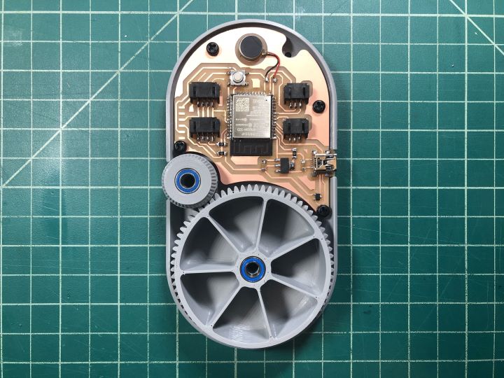
I took another step backwards, basically altering nothing about my Week 12 board except for replacing the RGB LED and piezo buzzer with a FTDI connector with corresponding pads, moving the location of the Hall effect sensor and the vibration motor, and changing the perimeter of the board to fit the enclosure. I even went as far (not far) to not move the location of the USB port, which meant I would have to cut a hole into the side of the enclosure to plug it in, but at this point, this is what had to be done. I simply didn’t have the time to assume that that change wouldn’t make a difference.

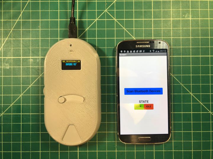
The fourth time was the charm. I loaded the following code onto the board, and all of the components functioned properly.
#include "BluetoothSerial.h"
#include <Adafruit_MPU6050.h>
#include <Adafruit_SSD1306.h>
#include <Adafruit_Sensor.h>

Adafruit_MPU6050 mpu;
Adafruit_SSD1306 display = Adafruit_SSD1306(128, 64, &Wire);

const int hallEffectPin = 25;
const int ledPinGreen = 26;
const int ledPinBlue = 27;
const int motor = 12;
int hallEffectState = 0;
int ledState = LOW;
int motorState = HIGH;

unsigned long previousMillis = 0;
const long interval = 500;

char Incoming_value = 0;
bool idleState = true;

BluetoothSerial SerialBT;

#if !defined(CONFIG_BT_ENABLED) || !defined(CONFIG_BLUEDROID_ENABLED)
#error Bluetooth is not enabled! Please run `make menuconfig` to and enable it
#endif

void setup() {
  // put your setup code here, to run once:

  pinMode(ledPinGreen, OUTPUT);
  pinMode(ledPinBlue, OUTPUT);
  pinMode(hallEffectPin, INPUT_PULLUP);
  pinMode(motor, OUTPUT);

  Serial.begin(115200);
  SerialBT.begin("Indispensable"); //Bluetooth device name
  Serial.println("Indispensable Pill Case");
  Serial.println("Remember What Empowers You");
  Serial.println("The device started, now you can pair it with bluetooth!");

  if (!mpu.begin()) {
    Serial.println("Sensor init failed");
    while (1)
      yield();
  }
  Serial.println("Found a MPU-6050 sensor");

  // SSD1306_SWITCHCAPVCC = generate display voltage from 3.3V internally
  if (!display.begin(SSD1306_SWITCHCAPVCC, 0x3C)) { // Address 0x3C for 128x32
    Serial.println(F("SSD1306 allocation failed"));
    for (;;)
      ; // Don't proceed, loop forever

}
}

void loop() {
  // put your main code here, to run repeatedly:
  if(SerialBT.available() > 0)
  {
    Incoming_value = SerialBT.read();
    Serial.print(Incoming_value);
    Serial.print("\n");
    if(Incoming_value == '0')
      idleState = true;
    else if(Incoming_value == '1')
      idleState = false;
  }

  unsigned long currentMillis = millis();

  if(idleState == false)
  {
    hallEffectState = digitalRead(hallEffectPin);

    if (hallEffectState == HIGH) {

    display.clearDisplay();
    display.setTextSize(1);
    display.setTextColor(WHITE);
    display.setCursor(0, 0);
    // Display static text
    display.println("*** INDISPENSABLE ***");
    display.println("---------------------");
    display.println("                     ");
    display.println("    TIME TO TAKE     ");
    display.println("     YOUR PILLS      ");
    display.display();


    digitalWrite(ledPinGreen,LOW);
    digitalWrite(ledPinBlue,HIGH);
    digitalWrite(motor, LOW);
    delay(100);
    digitalWrite(ledPinGreen,HIGH);
    digitalWrite(ledPinBlue,HIGH);
    digitalWrite(motor, LOW);
    delay(900);
  }

  else {

    sensors_event_t a, g, temp;
    mpu.getEvent(&a, &g, &temp);

    display.clearDisplay();
    display.setCursor(0, 0);

    Serial.print("Gyroscope ");
    Serial.print("X: ");
    Serial.print(g.gyro.x, 1);
    Serial.print(" rps, ");
    Serial.print("Y: ");
    Serial.print(g.gyro.y, 1);
    Serial.print(" rps, ");
    Serial.print("Z: ");
    Serial.print(g.gyro.z, 1);
    Serial.println(" rps");

    display.println("*** INDISPENSABLE ***");
    display.println("---------------------");
    display.print("       X: ");
    display.print(g.gyro.x, 1);
    display.println("");
    display.print("       Y: ");
    display.print(g.gyro.y, 1);
    display.println("");
    display.print("       Z: ");
    display.print(g.gyro.z, 1);

    display.display();
    delay(100);

    if (currentMillis - previousMillis >= interval) {
    // save the last time you blinked the LED
    previousMillis = currentMillis;

    // if the LED is off turn it on and vice-versa:
    if (ledState == LOW) {
      ledState = HIGH;
      motorState = HIGH;
    } else {
      ledState = LOW;
      motorState = LOW;
    }

  }

    // set the LED with the ledState of the variable:
    digitalWrite(ledPinBlue, ledState);
    digitalWrite(motor, motorState);
  }
  }

  else if (idleState == true) {
    display.clearDisplay();
    display.setTextSize(1);
    display.setTextColor(WHITE);
    display.setCursor(0, 0);
    // Display static text
    display.println("*** INDISPENSABLE ***");
    display.println("---------------------");
    display.println("                     ");
    display.println("    REMEMBER WHAT    ");
    display.println("    EMPOWERS YOU     ");
    display.display();

    digitalWrite(ledPinGreen,LOW);
    digitalWrite(ledPinBlue,HIGH);
    digitalWrite(motor, LOW);
    delay(100);
    digitalWrite(ledPinGreen,HIGH);
    digitalWrite(ledPinBlue,HIGH);
    digitalWrite(motor, LOW);
    delay(900);
  }

}
I felt dirty cutting into the enclosure, but I used a fine-tooth x-acto saw and diamond files, so it was about as precise as I could get it without re-printing the enclosure to account for the new board layout. I integrated all of the components into the enclosure, filming as I went.
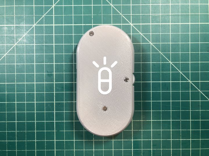
As a finishing touch, I applied one of the vinyl decals I created in Week 3 to the back of the enclosure. And with that, all that was left to do was make the slide and edit the video.

Jun 10
I downloaded KdenLive, which I found fairly intuitive to use. I brought all of the clips into the software, chopped them up, and added some slides I made in Adobe Illustrator. And with that, my project was ready to present.