- Group Assignment:
- probe an input device's analog levels and digital signals
- Individual Assignment:
- measure something: add a sensor to a microcontroller board
that you have designed and read it
- measure something: add a sensor to a microcontroller board
- Link to the group assignment page
- Document what I learned from interfacing an input device(s) to microcontroller and how the
physical property relates to the measured results - Document my design and fabrication process or link to previous examples
- Explain the programming process/es I used
- Explain problems and how I fixed them
- Include original design files and source code
- Include a ‘hero shot/video’ of my board
Group Assignment
Input devices
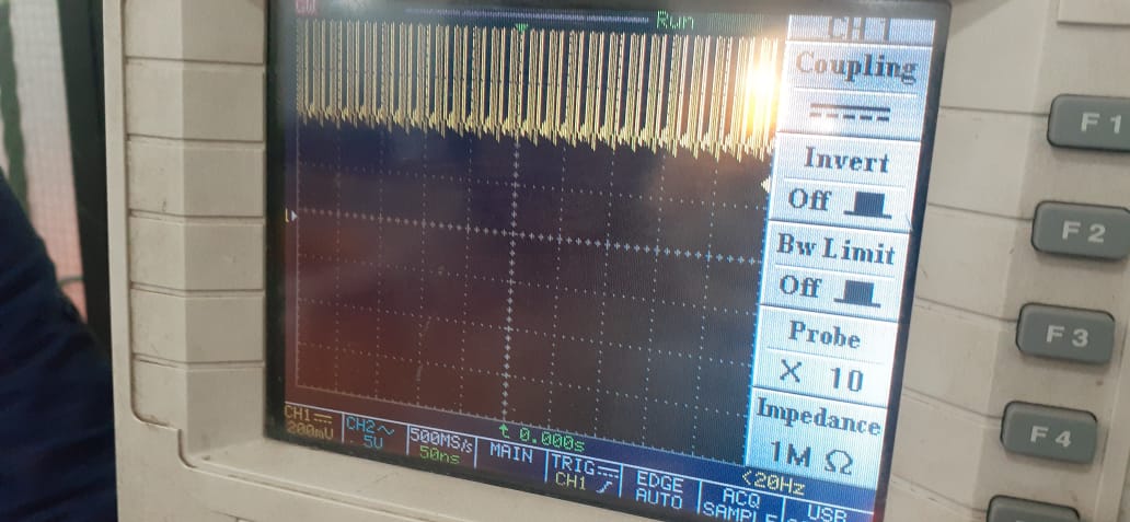
In this assignment we are going to probe the analog and digital levels of input devices. We choose the microphone module and PIR sensor for this assignment.
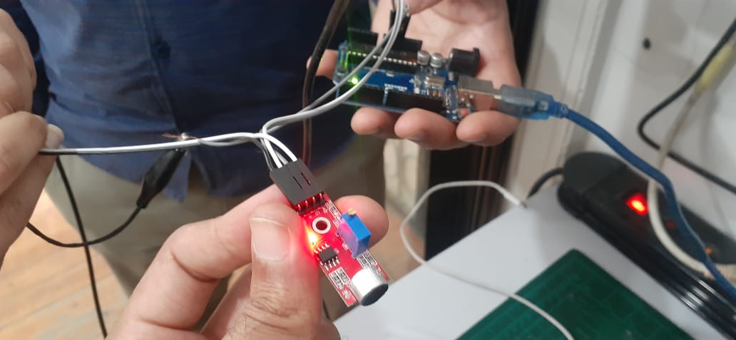
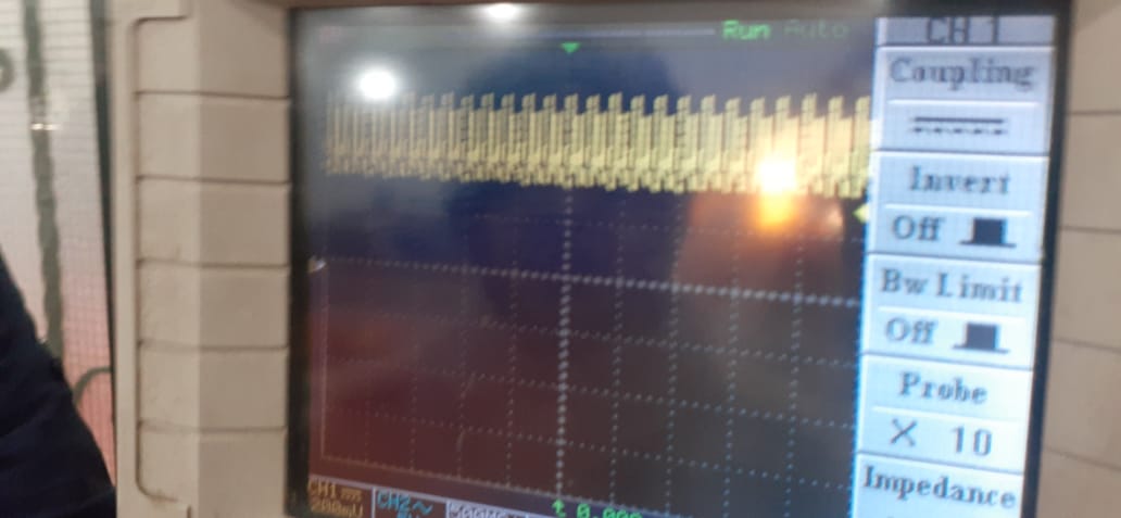
We used the oscilliscope to probe the analog ouput pin of the microphone module. When someone talks near the microphone, the below waveform is observed on the oscilliscope.
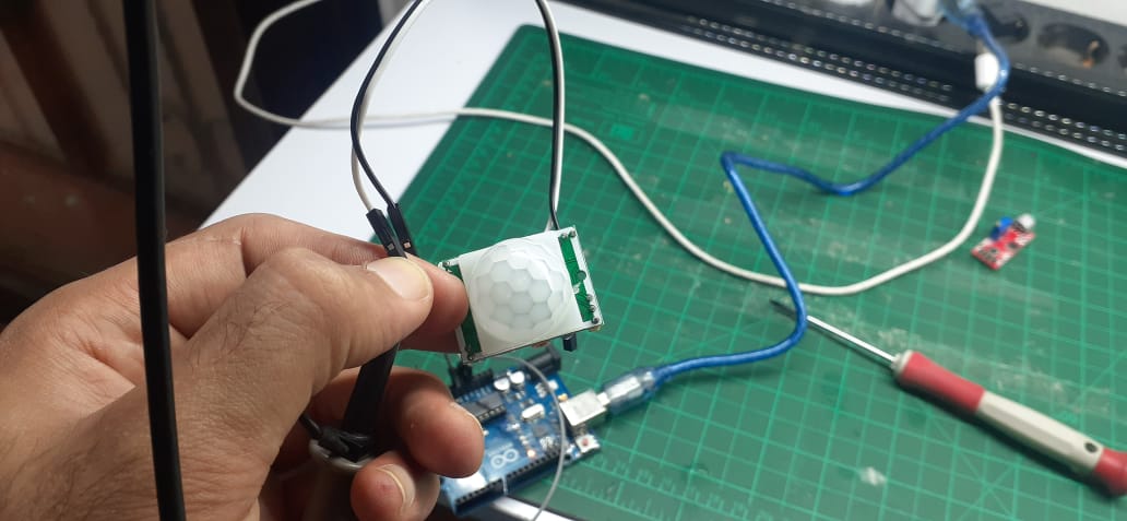
We used the oscilliscope to probe the digital ouput pin of the PIR sensor. When a motion is detected the digital ouput is observed to be HIGH then after a while it turns off to the default state of level LOW.
Understanding HC-SR04
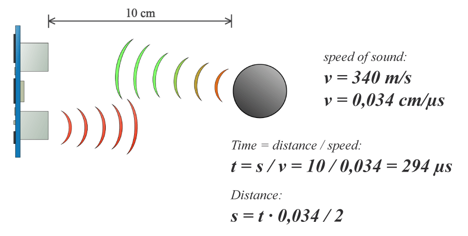
The HCSR04 is an Ultrasonic Sensor that uses sonar to determine the distance to an object. It consists of a transmitter and receiver. When the (trig pin) gets an electrical signal, the transmitter sends a sound signal: a high-frequency sound that can't be heard by humans. When the sound signal finds an object, it is reflected and the receiver receives it and changes it into electrical signal on the (echo pin).
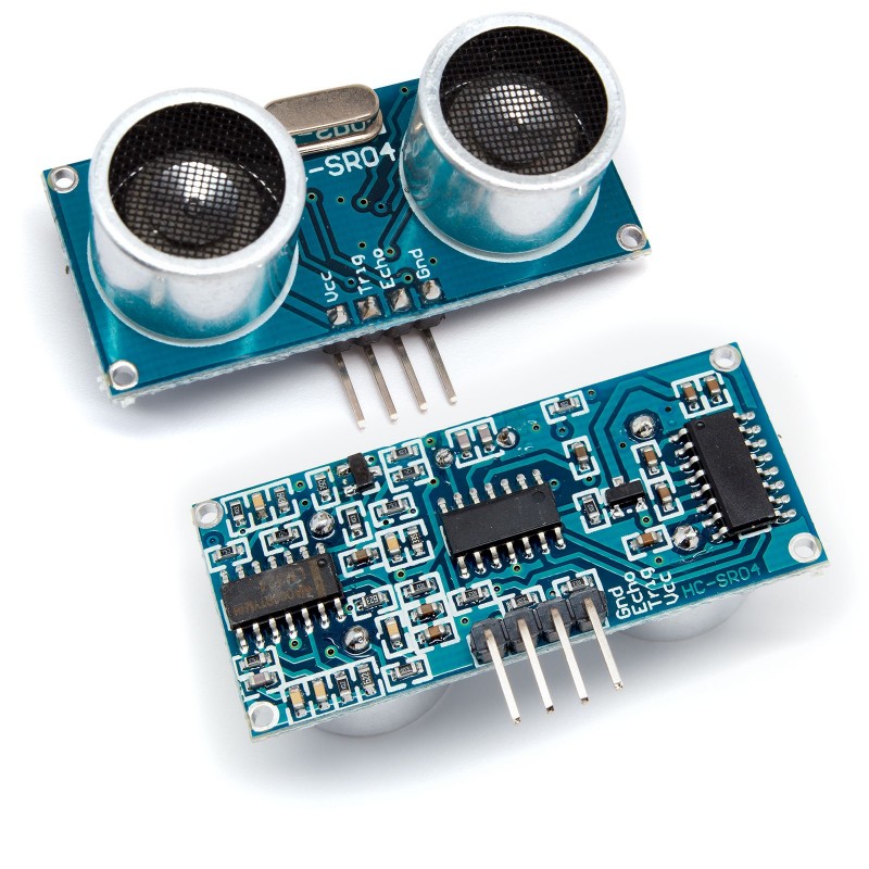
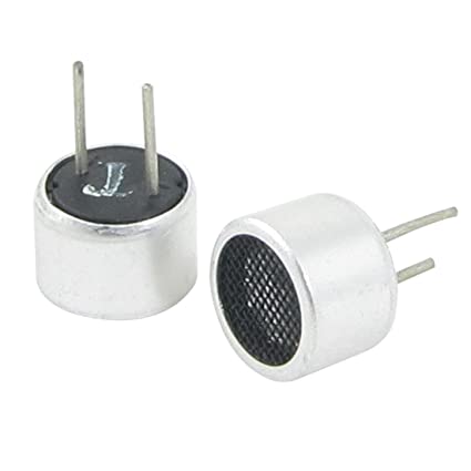
The core components of the Ultrasonic Sensor are the TX and RX Pair
The module has the following specs are:
- Measuring Angle: 30 degree
- Resolution : 0.3 cm
- Ranging Distance : 2cm – 400 cm
In order to measure the distance the Trig on should be at High State for 10 µs. That will send out an 8 cycle sonic burst which will travel at the speed sound and it will be received in the Echo pin. The Echo pin will output a signal when the sound comes back again.
Measuring the delay time between the sending and receiving can indicate the distance of the object knowing that Time = Distance / Speed and the speed of sound is 340 m/s
HC-SR04 PCB Design
This Is Neil's HC-04 So we will Remodel it on Ki CAD and Fabricate it
The Component's we Need as the Followuing
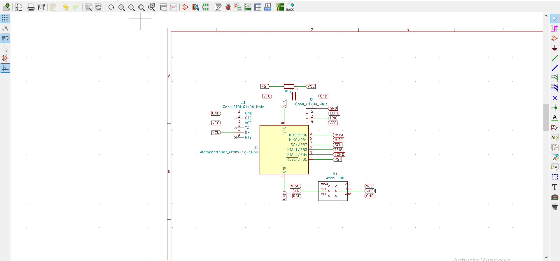
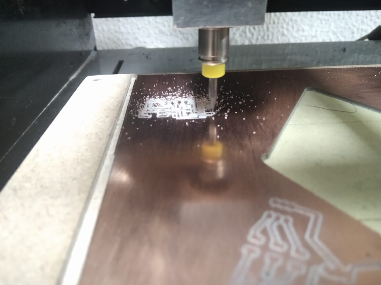
And then Let's Go to make the Board
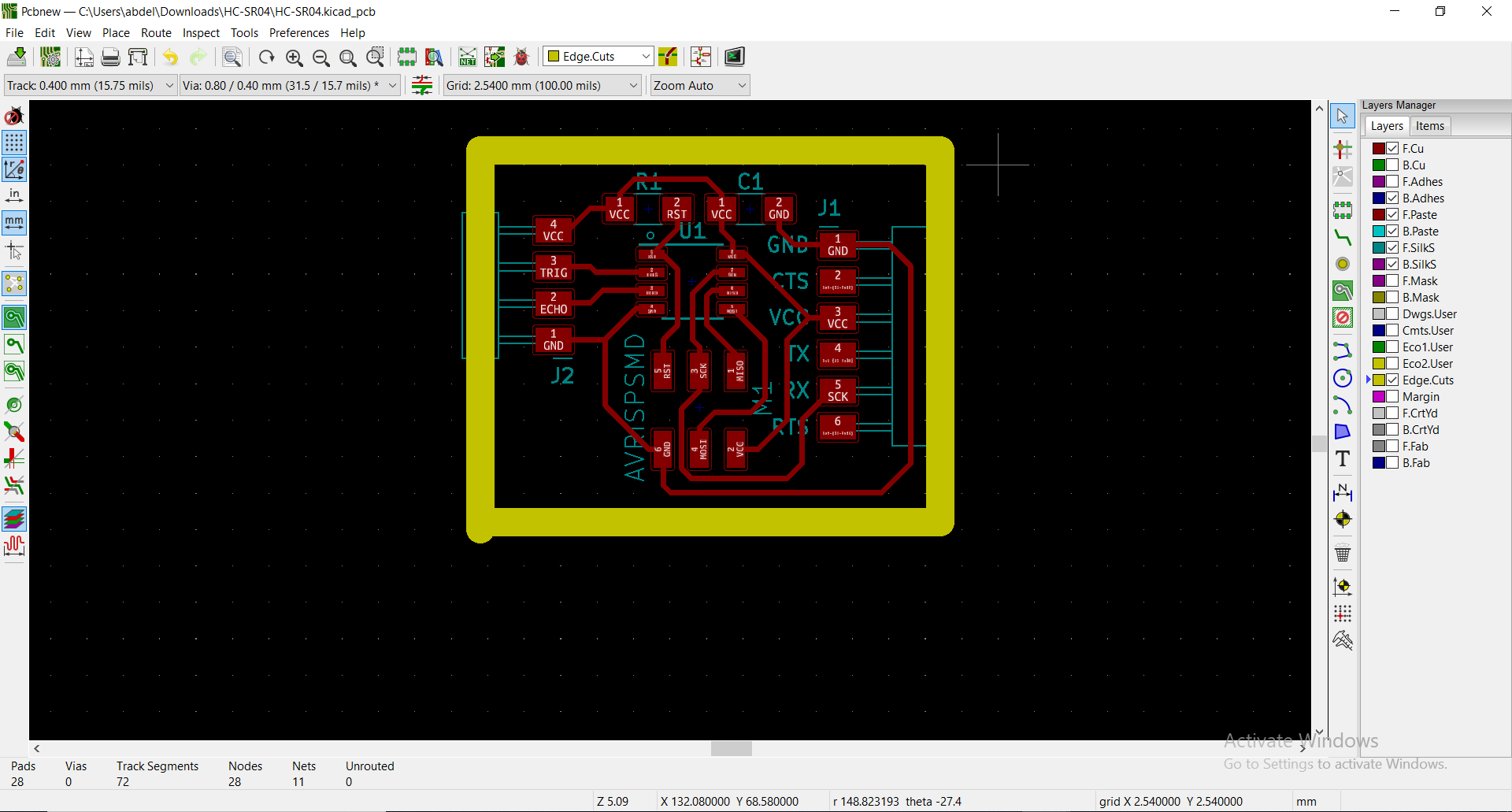
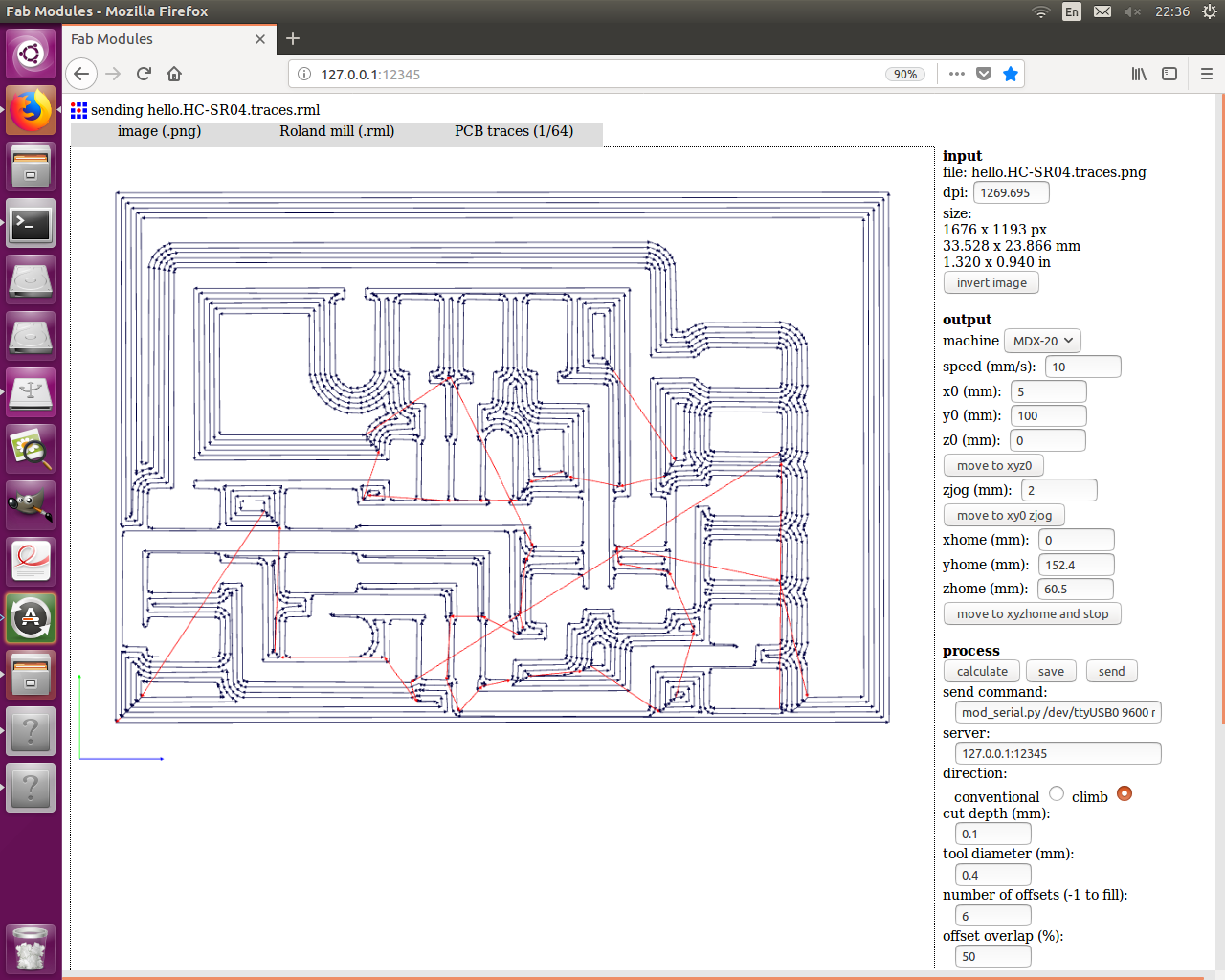
So let's see the Png's files

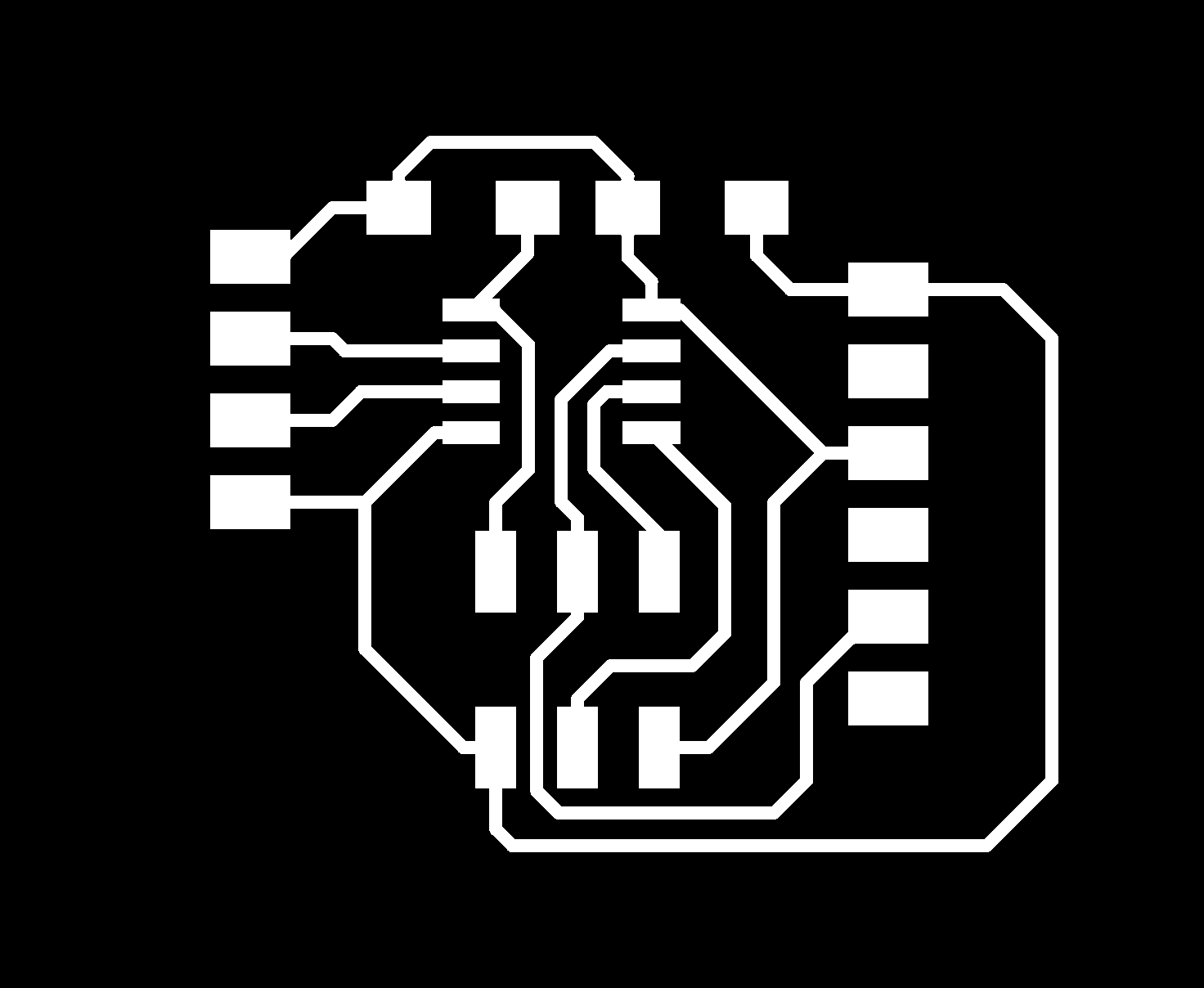
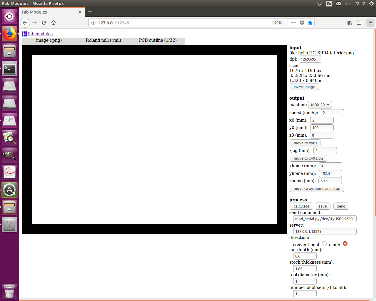
So Let's put the PNG on FABMODULES and start To fabricate the PCB
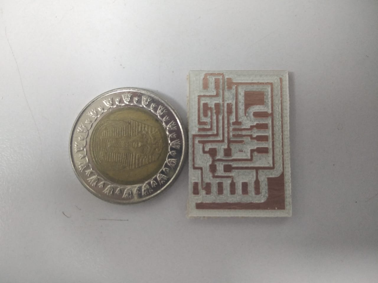
So in the Next Step is Testing and Opearate the ultrasonic
HC-SR04 PCB Testing
The code is based on the algorithm mentioned above. The loop function triggers the
ultrasonic to send the a sound wave, then waits for the signal to return back using the
pulseIn() function. The distance is calculated using the equation mentioned before
as well.
at first I tried to upload neil's Code but it didn't Work well for me
    //
// hello.HC-SR04.c
//
// HC-SR04 sonar hello-world
//    9600 baud FTDI interface
//
// Neil Gershenfeld 11/15/15
// (c) Massachusetts Institute of Technology 2015
//
// This work may be reproduced, modified, distributed,
// performed, and displayed for any purpose. Copyright is
// retained and must be preserved. The work is provided
// as is; no warranty is provided, and users accept all
// liability.
//

#include
#include

#define output(directions,pin) (directions |= pin) // set port direction for output
#define set(port,pin) (port |= pin) // set port pin
#define clear(port,pin) (port &= (~pin)) // clear port pin
#define pin_test(pins,pin) (pins & pin) // test for port pin
#define bit_test(byte,bit) (byte & (1 << bit)) // test for bit set
#define bit_delay_time 102 // bit delay for 9600 with overhead
#define bit_delay() _delay_us(bit_delay_time) // RS232 bit delay
#define half_bit_delay() _delay_us(bit_delay_time/2) // RS232 half bit delay
#define char_delay() _delay_ms(10) // char delay

#define serial_port PORTB
#define serial_direction DDRB
#define serial_pin_out (1 << PB2)
#define trigger_port PORTB
#define trigger_direction DDRB
#define trigger_pin (1 << PB3)
#define echo_pins PINB
#define echo_direction DDRB
#define echo_pin (1 << PB4)

#define timeout 255

void put_char(volatile unsigned char *port, unsigned char pin, char txchar) {
   //
   // send character in txchar on port pin
   //    assumes line driver (inverts bits)
   //
   // start bit
   //
   clear(*port,pin);
   bit_delay();
   //
   // unrolled loop to write data bits
   //
   if bit_test(txchar,0)
      set(*port,pin);
   else
      clear(*port,pin);
   bit_delay();
   if bit_test(txchar,1)
      set(*port,pin);
   else
      clear(*port,pin);
   bit_delay();
   if bit_test(txchar,2)
      set(*port,pin);
   else
      clear(*port,pin);
   bit_delay();
   if bit_test(txchar,3)
      set(*port,pin);
   else
      clear(*port,pin);
   bit_delay();
   if bit_test(txchar,4)
      set(*port,pin);
   else
      clear(*port,pin);
   bit_delay();
   if bit_test(txchar,5)
      set(*port,pin);
   else
      clear(*port,pin);
   bit_delay();
   if bit_test(txchar,6)
      set(*port,pin);
   else
      clear(*port,pin);
   bit_delay();
   if bit_test(txchar,7)
      set(*port,pin);
   else
      clear(*port,pin);
   bit_delay();
   //
   // stop bit
   //
   set(*port,pin);
   bit_delay();
   //
   // char delay
   //
   bit_delay();
   }

int main(void) {
   //
   // main
   //
   static unsigned char high,low;
   //
   // set clock divider to /1
   //
   CLKPR = (1 << CLKPCE);
   CLKPR = (0 << CLKPS3) | (0 << CLKPS2) | (0 << CLKPS1) | (0 << CLKPS0);
   //
   // initialize output pins
   //
   set(serial_port,serial_pin_out);
   output(serial_direction,serial_pin_out);
   clear(trigger_port,trigger_pin);
   output(trigger_direction,trigger_pin);
   //
   // start counter
   //
   TCCR0B |= (1 << CS00); // prescale /1
   //
   // main loop
   //
   while (1) {
      //
      // trigger pulse
      //
      set(trigger_port,trigger_pin);
      _delay_us(10);
      clear(trigger_port,trigger_pin);
      //
      // wait for echo rising edge
      //
      high = 0;
      TCNT0 = 0;
      TIFR |= (1 << TOV0);
      while (1) {
         if ((echo_pins & echo_pin) != 0) // check for rising edge
            break;
         if ((TIFR & (1 << TOV0)) != 0) { // check for counter overflow
            high += 1;
            if (high == timeout)
               break;
            TIFR |= (1 << TOV0);
            }
         }
      //
      // rising edge found, wait for falling edge
      //
      high = 0;
      TCNT0 = 0;
      TIFR |= (1 << TOV0);
      while (1) {
         if ((echo_pins & echo_pin) == 0) { // check for falling edge
            low = TCNT0;
            break;
            }
         if ((TIFR & (1 << TOV0)) != 0) { // check for counter overflow
            high += 1;
            if (high == timeout)
               break;
            TIFR |= (1 << TOV0);
            }
         }
      //
      // send count with framing
      //
      put_char(&serial_port,serial_pin_out,1);
      put_char(&serial_port,serial_pin_out,2);
      put_char(&serial_port,serial_pin_out,3);
      put_char(&serial_port,serial_pin_out,4);
      put_char(&serial_port,serial_pin_out,low);
      put_char(&serial_port,serial_pin_out,high);
      //
      // delay before next cycle
      //
      _delay_ms(10);
      }
   }
So I had to write my code and See If it works or not !
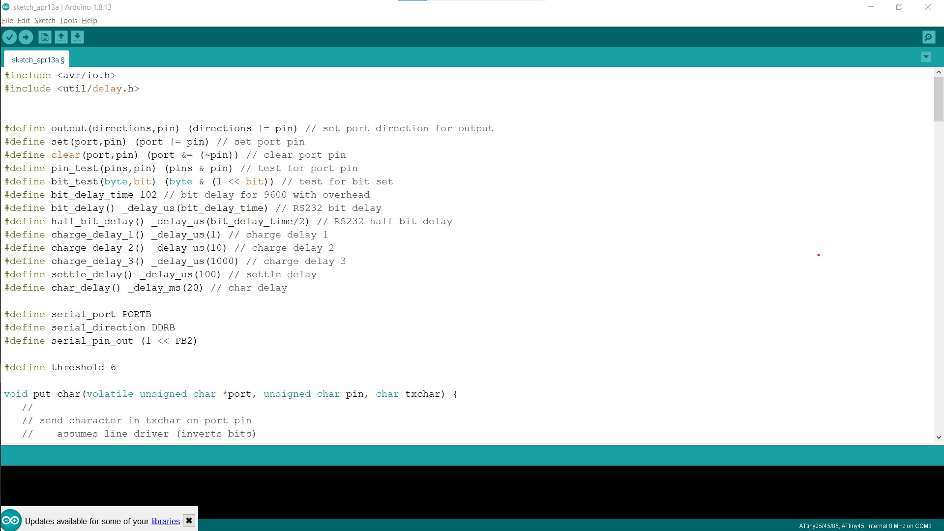
What Actually here I did is..... To write the Code In C arduino and Upload it using Programmmer, and See what will happen
< mySerial> it's Actually a Library Serial
#include <SoftwareSerial.h>
SoftwareSerial mySerial(0, 1); // RX, TX
const int trigPin = 4; // Trigger Pin of Ultrasonic Sensor
const int echoPin = 3; // Echo Pin of Ultrasonic Sensor

void setup() {
    mySerial.begin(9600); //Setub the serial rate between the board and ultraSonic
    pinMode(trigPin, OUTPUT); //make the trigger pin as output
    pinMode(echoPin, INPUT); //make the echo pin as input
}

void loop() {

    long duration, cm;
    digitalWrite(trigPin, LOW);
    delayMicroseconds(2);
    digitalWrite(trigPin, HIGH);
    delayMicroseconds(10);
    digitalWrite(trigPin, LOW);
    // here is the times that ultrasonic sends the waves during spacific time (Standerd)

    duration = pulseIn(echoPin, HIGH);
    cm = duration * 0.034 / 2 ;
    // here is the equation upove of how to calculate the distace
    mySerial.print(cm);
    mySerial.print("cm");
    mySerial.println();
    delay(100);
}
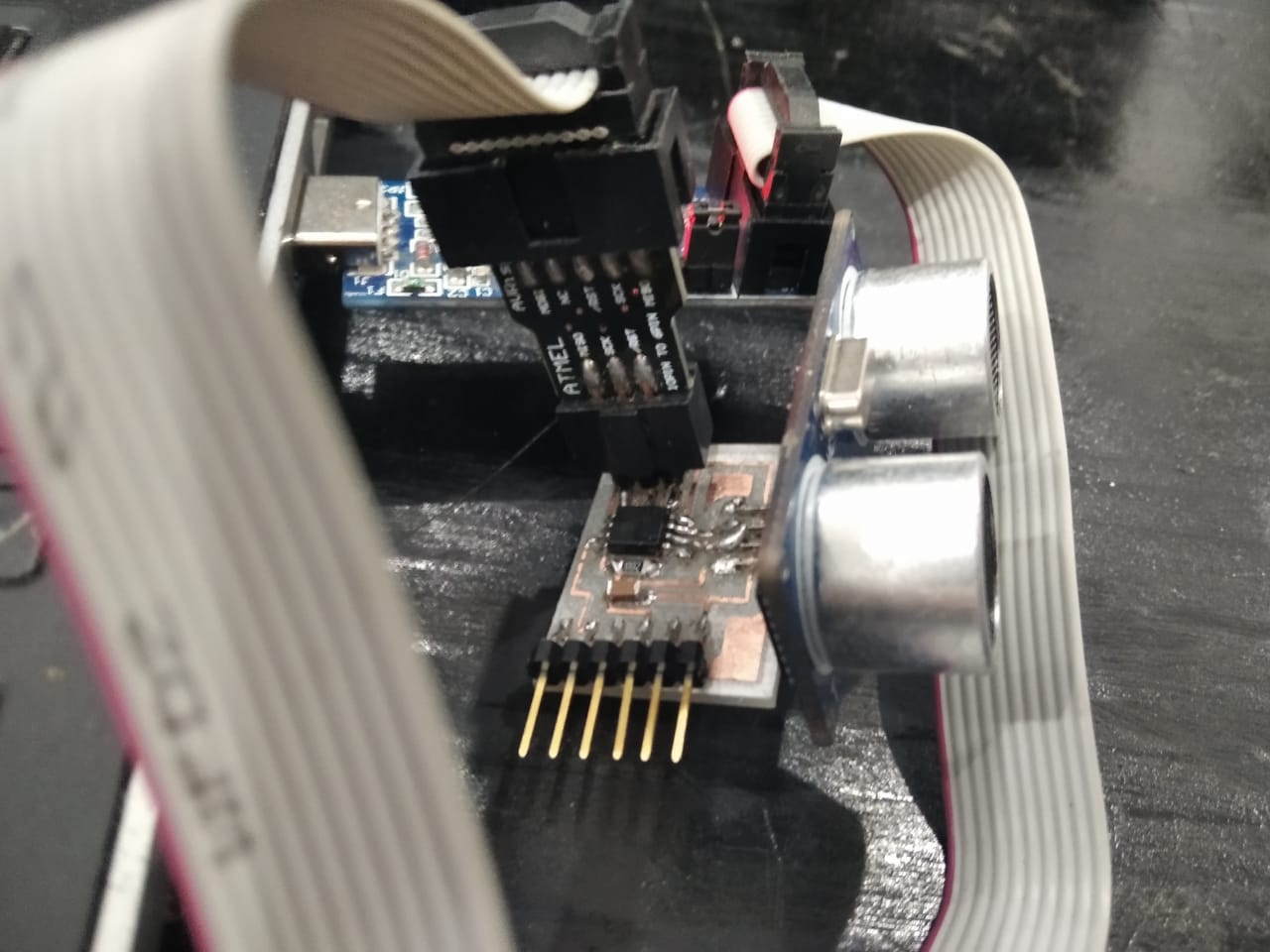
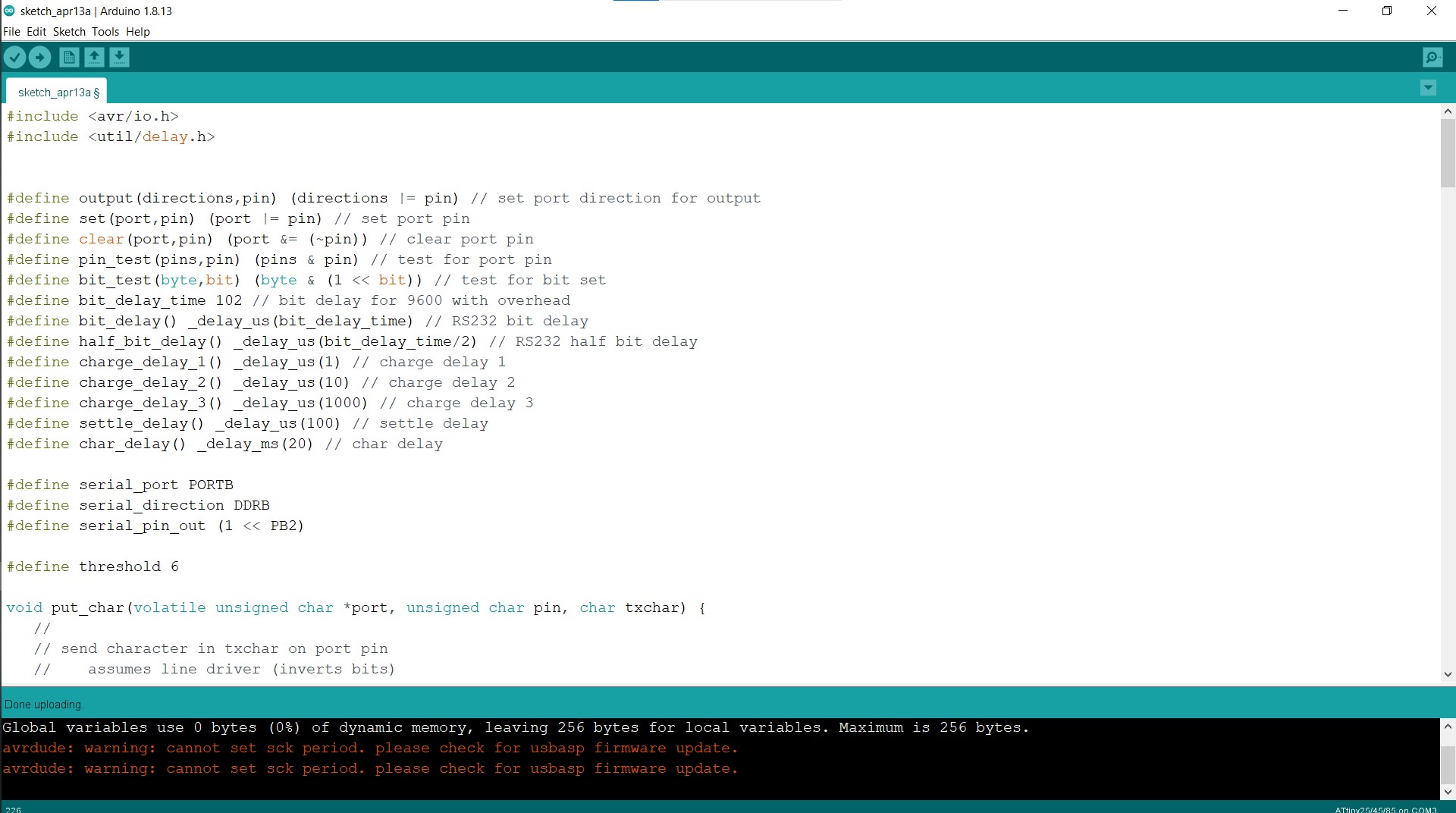
So Attach the Usbasp in the Computer
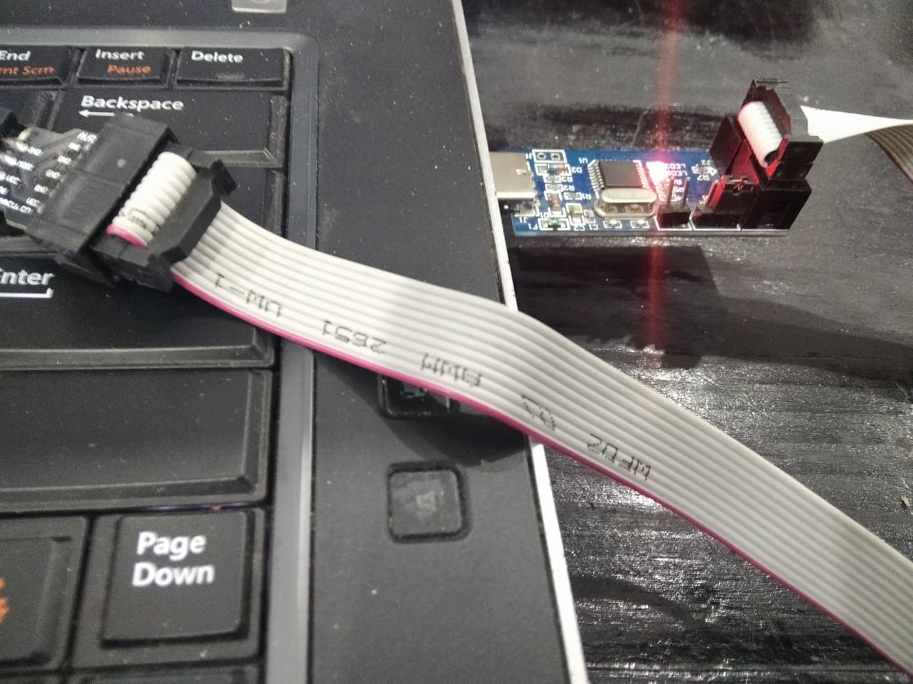
And then attack the PCB and then Start to Upload the Code
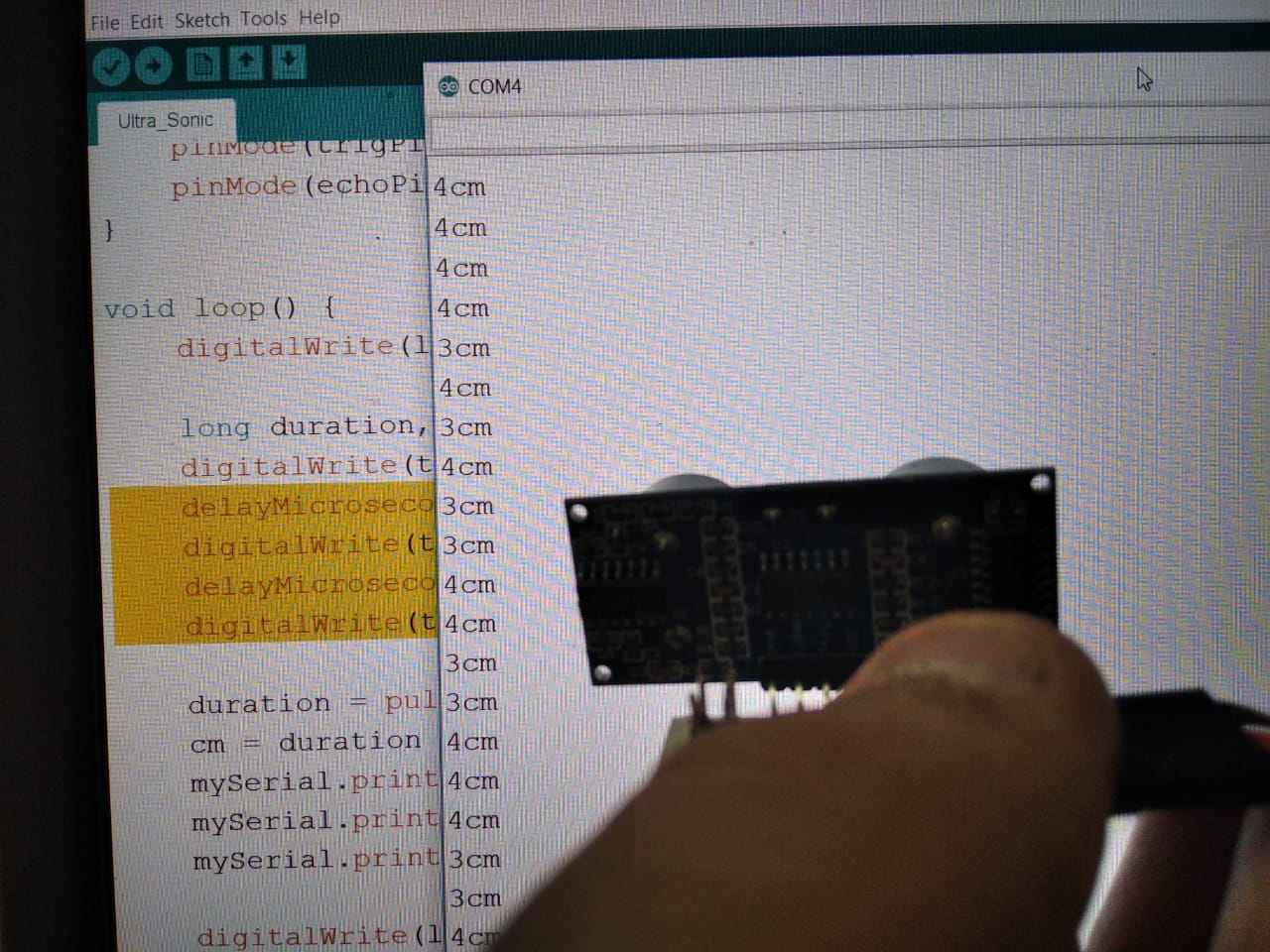
I started the Serial Monitor and began moving my hand in front of the sensor to read different distances.
Here is a video of this operation.
and Now for the Video