7. Computer controlled machining
Group Assignment
Hear about it Here
Performed on Simplex , a huge Egyptian machine , and observed as we had a joint designed and cut .
We wanted to characterise the machine , or simply know what to keep in mind while designing and generating toolpath .
Safety
First we must take the safety precautions , Handling a big powerful machine like the Simplex without being careful is very risky .
1 - Wear safety stuff , the glasses , gloves and the noise canceller while operating and fixing the wood sheet .
2 - Keep a safe distance between you and the machine while it’s working .
3 - After cutting before checking your pieces , make sure to turn off the power and the spindle .
4 - Let a machine specialist check your toolpath to make sure all settings are correct before starting the machine .
Characterizing
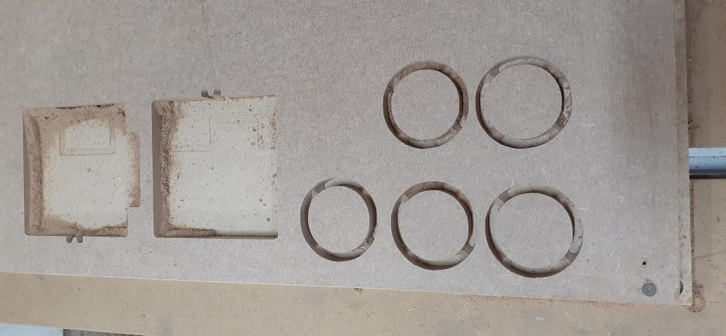
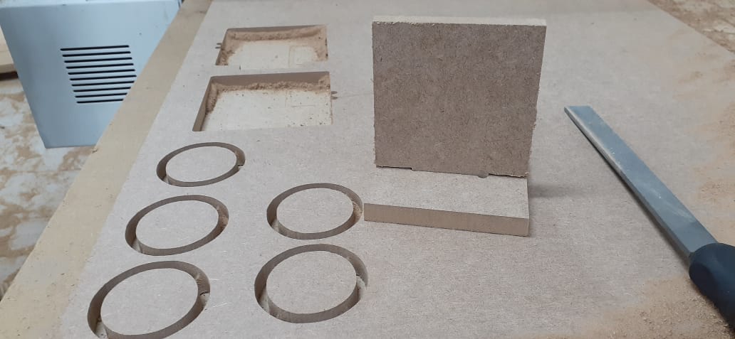
We cut 5 circles , each had a different toolpath , On MDF 12 mm .
Each toolpath had different RPM and feed rate .
RPM is the number of revolutions per minute of the spindle . Each material have a specific RPM to smoothest cutting .
Different values were 10000 , 12000 & 15000 rpm .
Feed rate is the speed of the spindle moving in the material , Too slow might burn the material and too fast will result into a rough finish .
Feed rate values were 3000 , 4500 , 6000 , 7000 & 8000 mm/min
Went off to testing these values on the 12mm MDF , but they all came out acceptable with very slight differences .
I understood this was because we tested on MDF which is considered not of the hardest materials .
Different RPM and feed rates might have resulted differently with Plywood for example as it’s harder .
Joints
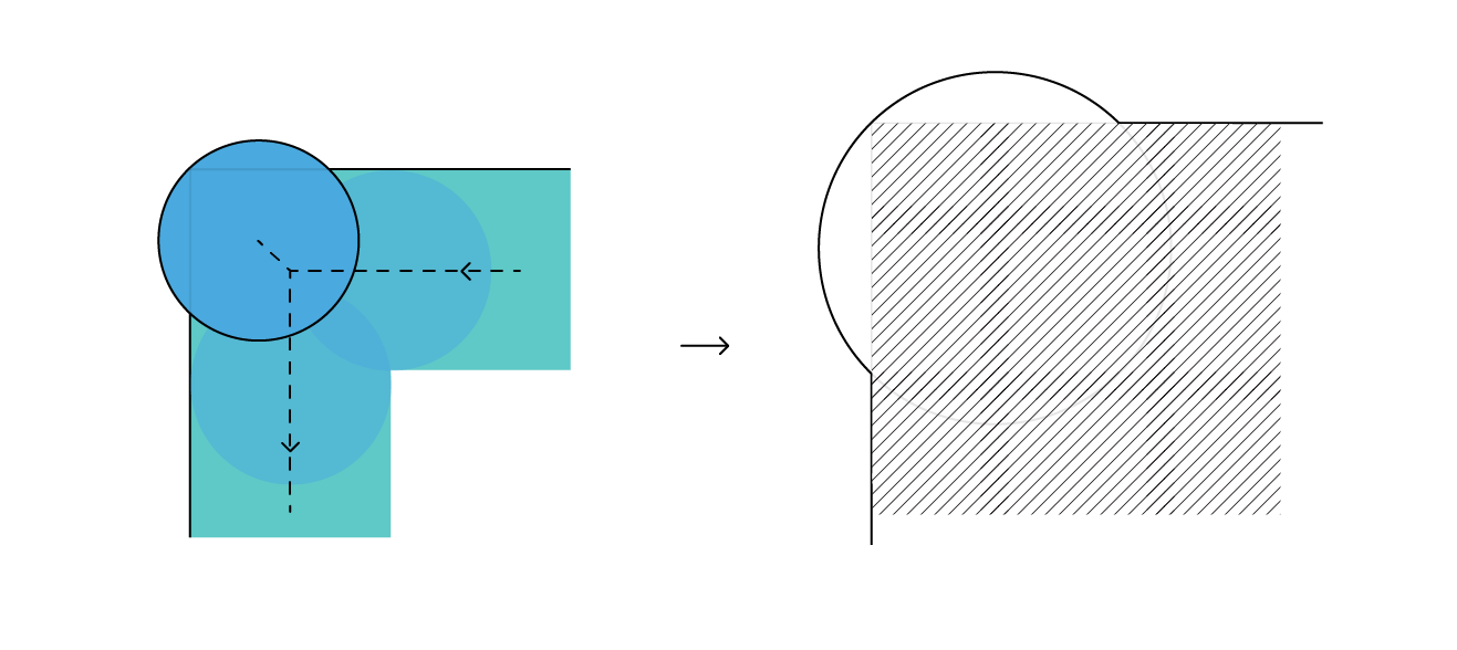
Last thing we did was testing fixation between 2 pieces .
We milled a slot with dog bones in the corners , and another pieces with a tooth to go in the slot .
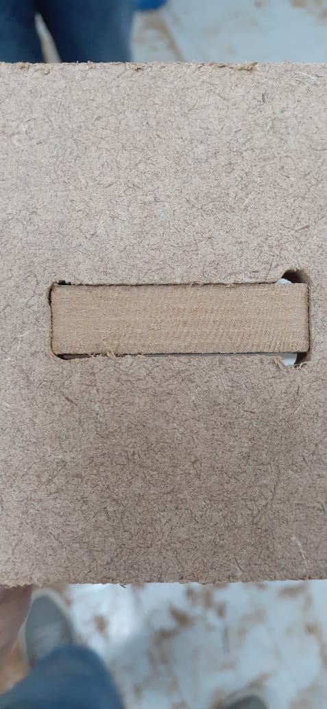
This helped me understand why we add these dog bones . It’s due to slots being cut by a round end mill .
If the design didn’t have a dog bone in the inner corners , they will come out not as a right angle but more like a fillet And the tooth won’t fit in correctly .
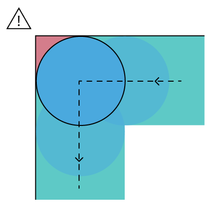
But with dog bone , it creates enough space for tooth to fit in completly .
Design
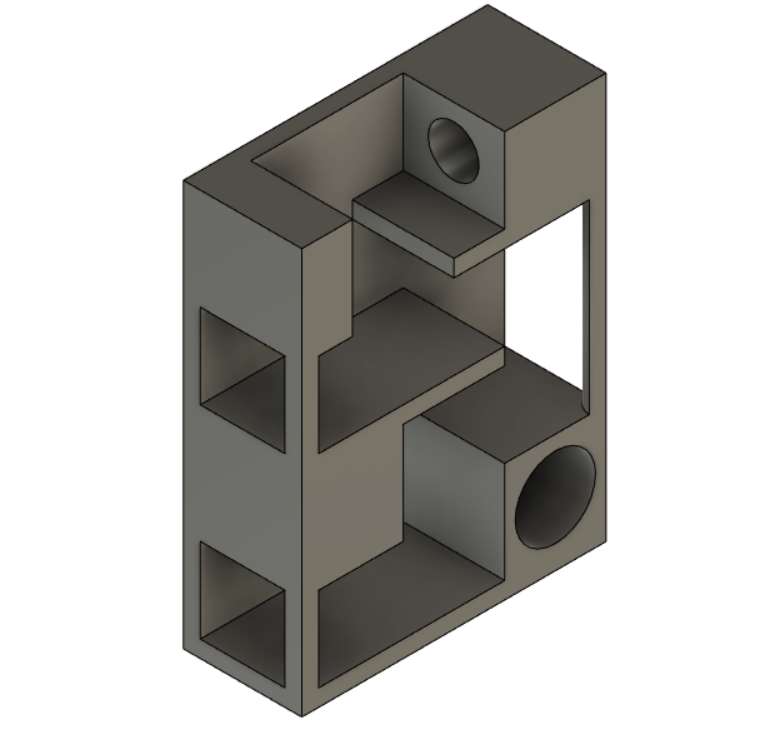
Using Fusion , I decided to make a cat tower , a part of my final project .
First I designed the whole thing as a concept .
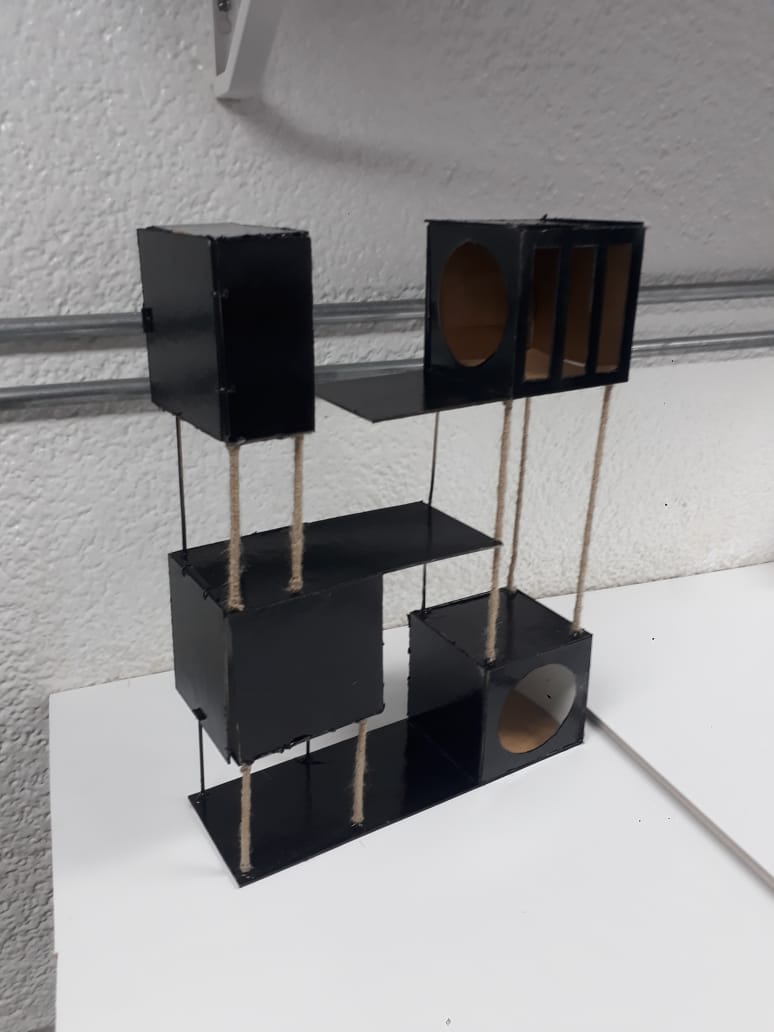
Built a prototype to easily visualize parts and how they assemble together .
It’s made of cardboard and sticks .
Fusion
Went again to Fusion to draw my files .
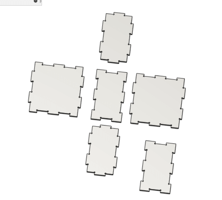
Teeth
We learned the the walls in any design can fit together by teeth , they have to be parametric so we can edit the wood thickness depending on its availability .
And they should have the dog bone grove so the teeth can fit together . It’s also parametric to edit based on the available bits / endmills .
Came across this tool to create automatically dog bone for the sketch , but didn’t try it yet . So I’m keeping it here to try in the future .
Rooms
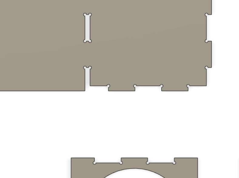
Finished drawing each room in the Cat tower .
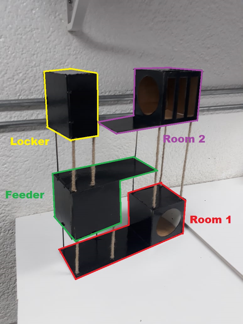
Here is Room 1 , Just a closed room with a circle door for cats and extended shelf .
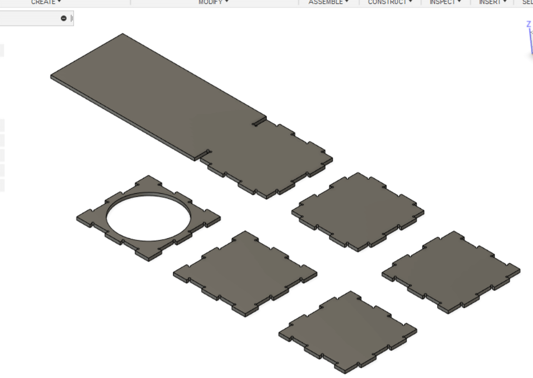
Room 2 , very similar to room 1 yet it has a shorter shelf and extra window for cats to observe around and judge me for not feeding them a fifth lunch .
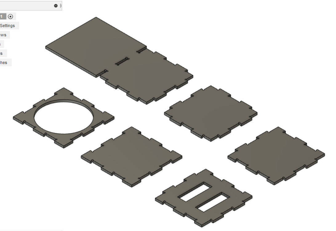
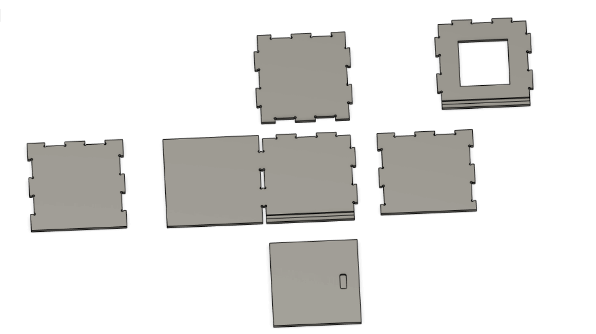
The locker , closed box I will print a handle for it later .
And the Feeder , a box with an openning at the buttom to drop food and a sliding door to refill the food tank
Cutting
Made on MDF of 12 mm thickness .
Prepared the cutting route on Aspire
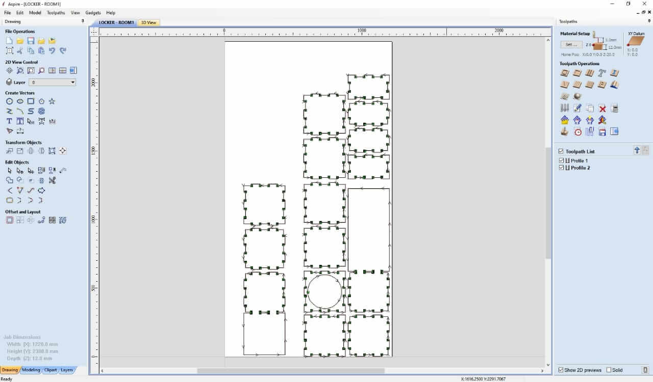
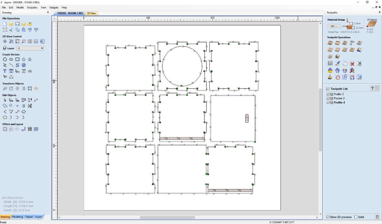
ToolPath
To start with Aspire , I watched this Tutorial
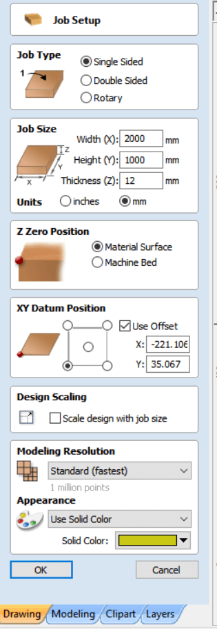
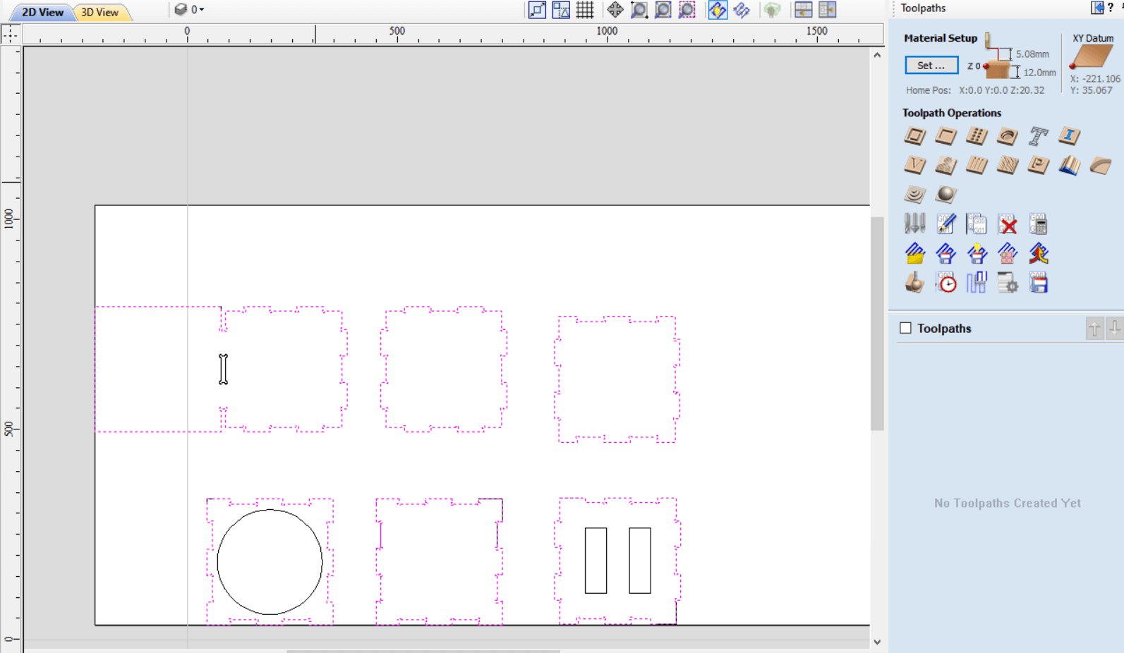
First we open our DXF , and setup the job ,
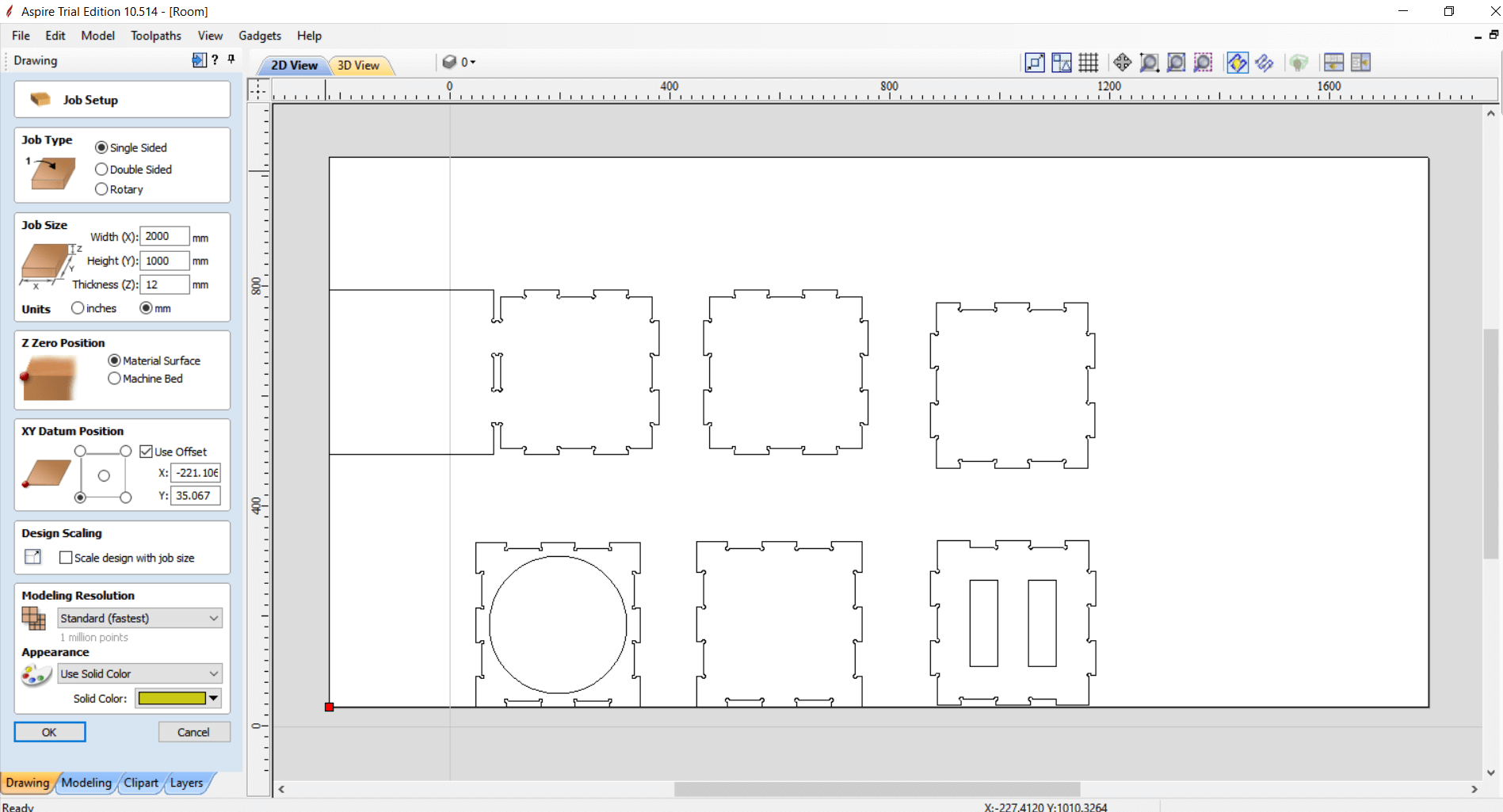
Handling the dimensions of the sheet we’re using and where to setup origin .
From Toolpaths menu , we show toolpaths tab
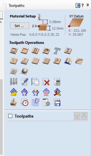
Check the material setup
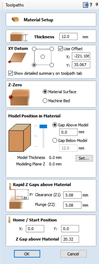
Most important thing is Rapid Z Gaps to make sure it’s high enough the tool won’t hit anything while it’s moving .
Next Profile tool path
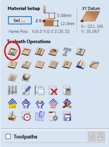
We select part to be cut on the outer to preserve their inner .
Editing the tool settings is crucial ,
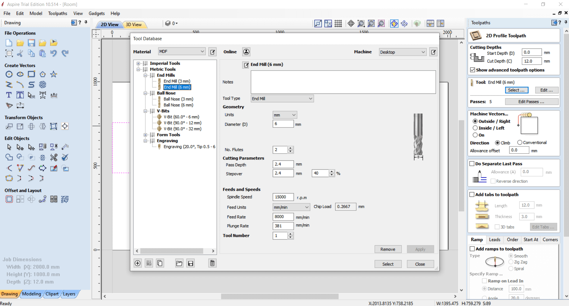
First select the tool we are using .
Setting the spindle speed and feed rate is important and varies from a material to another .
15000 RPM and 8000 mm/min feed rate were most effective based on our trials on the group assignment .
Also make sure Machine vector is set to Outside .
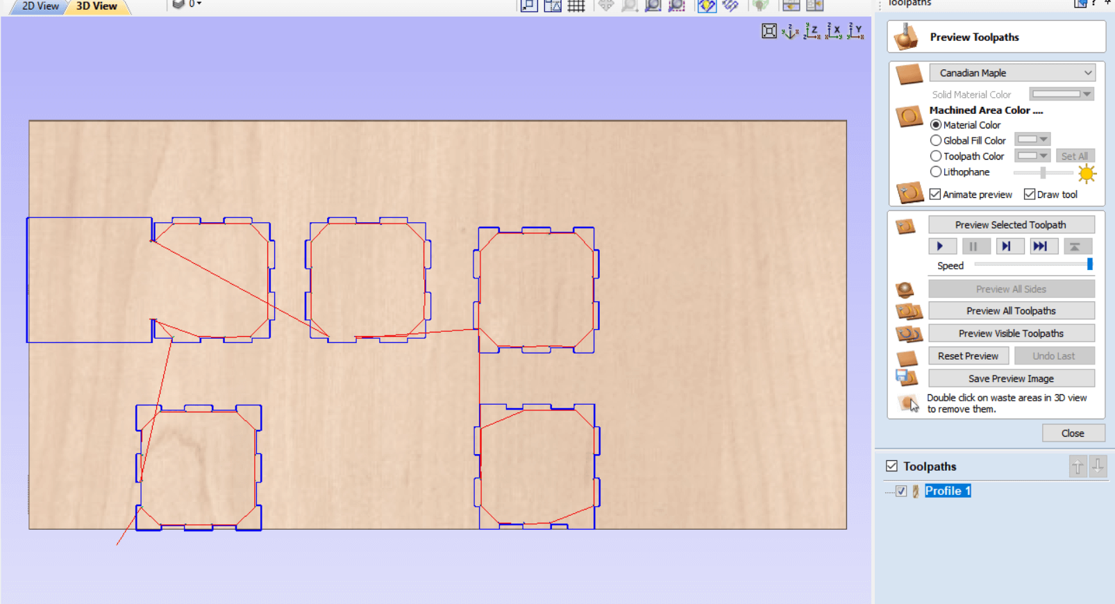
And we have the first profile ready
Let’s select parts to be cut on the inside to preserve their outer .
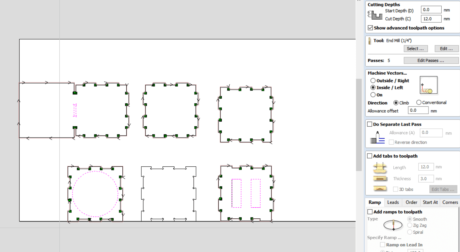
Same setting except for Machine vector set to Inside .
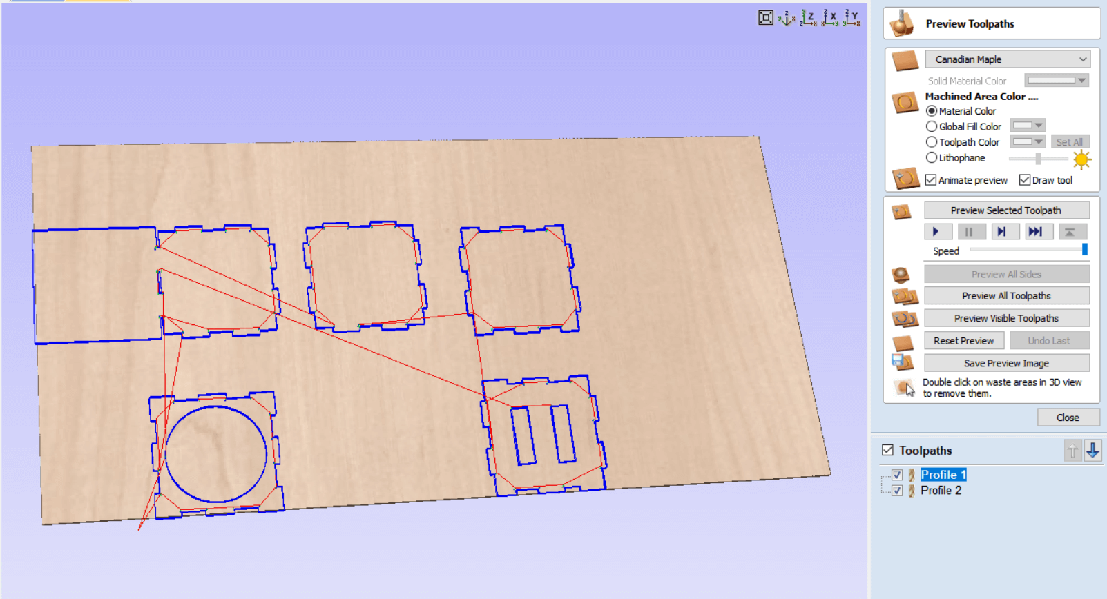
All cutting profiles are ready , let’s send to the machine
Simplex
Machine is controlled using Mach3 , it works on most Windows PC’s to control the motion of motors (stepper & servo) by processing G-Code.
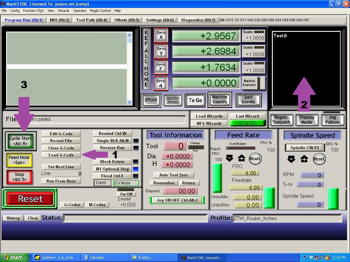
1 . We load the profiles we prepared
2 . The screen shows the parts to be cut
3 . We click Cycle Start to begin cutting
Here is the cutting on the great Simplex,
After assembly & spray
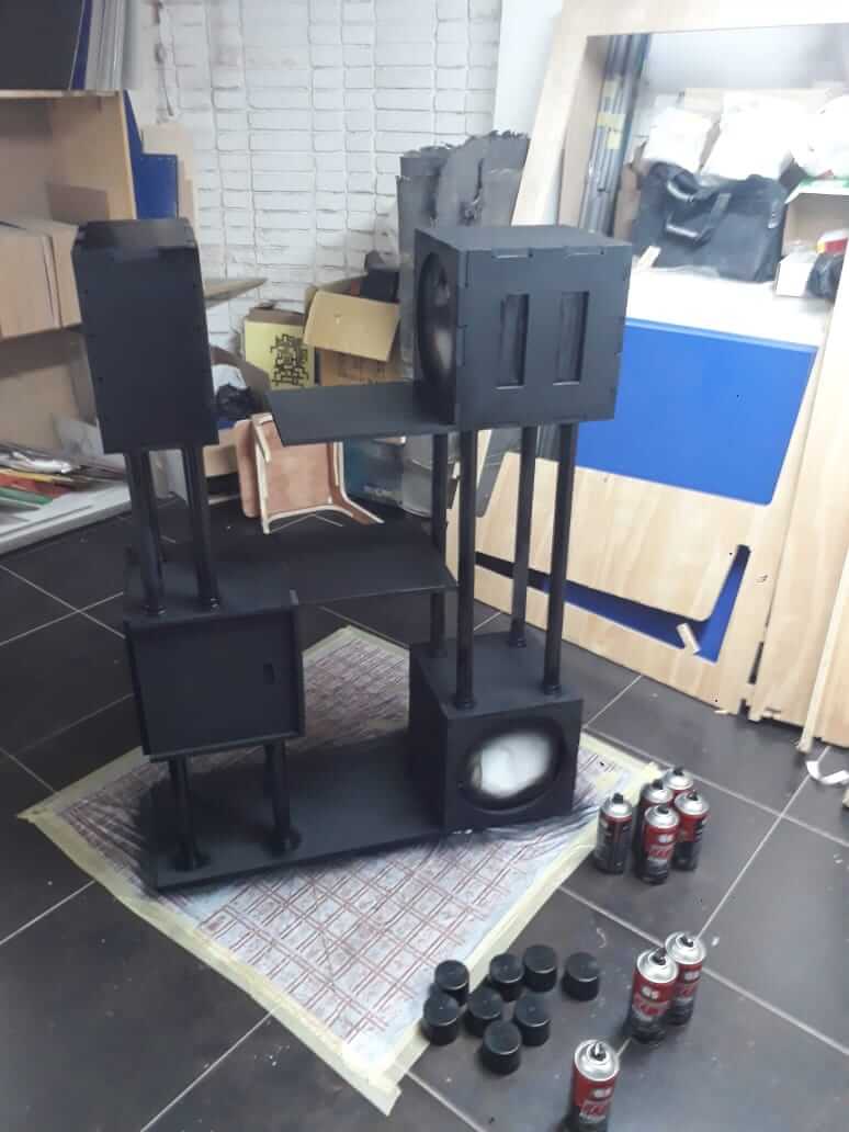
I used PVC tubes for scratching columns .
3D printed fixation bases for them .
And I marked where the bases to be fixed using the laser cutter .
Files
Fusion files for the Rooms