12. Molding and casting
The assignment this week reaquires to design a mold around the stock and tooling that we can use to create shapes in diverse types of materials. It is interesting to mill it using different depths.
Molding/Casting One - Panda
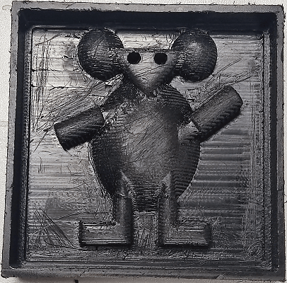
Previously I have used the image bellow to design the vinyl cut. I decided to use it again to create the mold for then make something that my daughter can play and enjoy it (she loves panda).

Drawing
I started the assignment drawing the image in a shape using fusion360 using different depth.
-
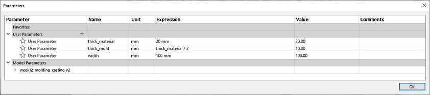
I added the necessary parameters for the drawing.
-
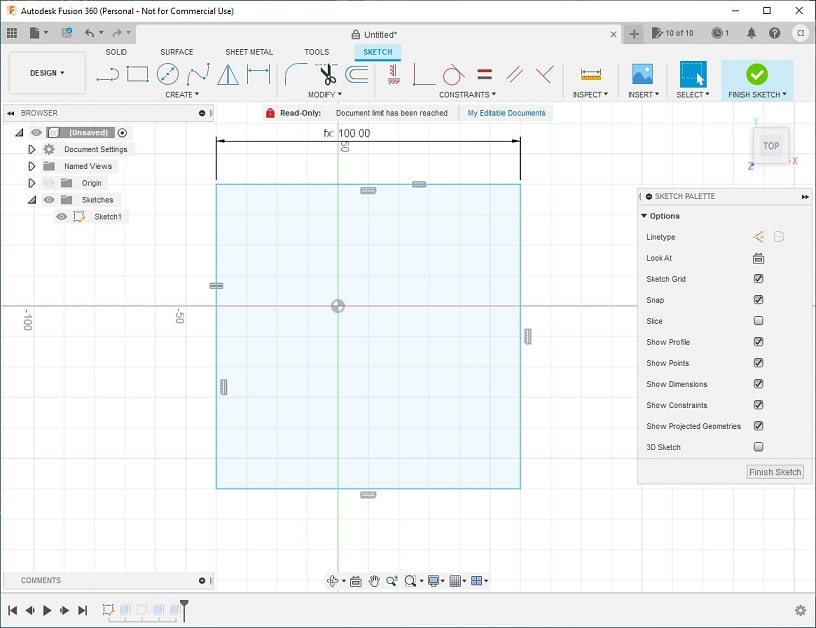
I have added a square in a simple sketch with the dimensions width X width.
-
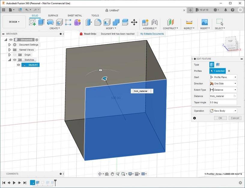
Create a extrude for the square which will represent the material we have available to make the mold.
-
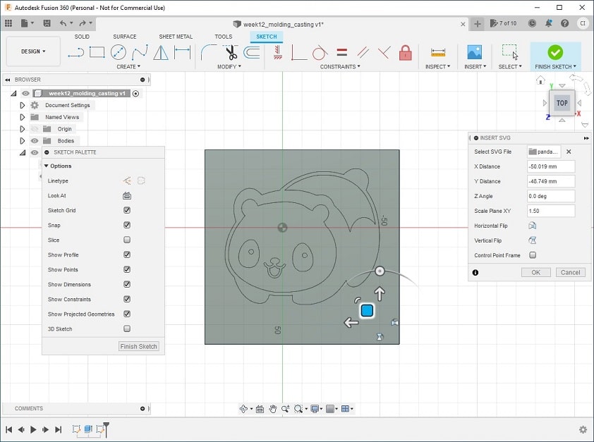
Edited the image using inkscape. Create the bitmap of the image to extract the lines; removed all points not necessary added from the bitmap; and adjusted to keep the same image lines. This is an important step because fusion accept to add SVG files in the sketch that can be used in the designing. This way it was possible to create the shape of panda in the design of the material.

-
Import the SVG file of the panda into a sketch using the top of the material and turned to fit the center of the material. I had also to adjust the scale to make it bigger.
-
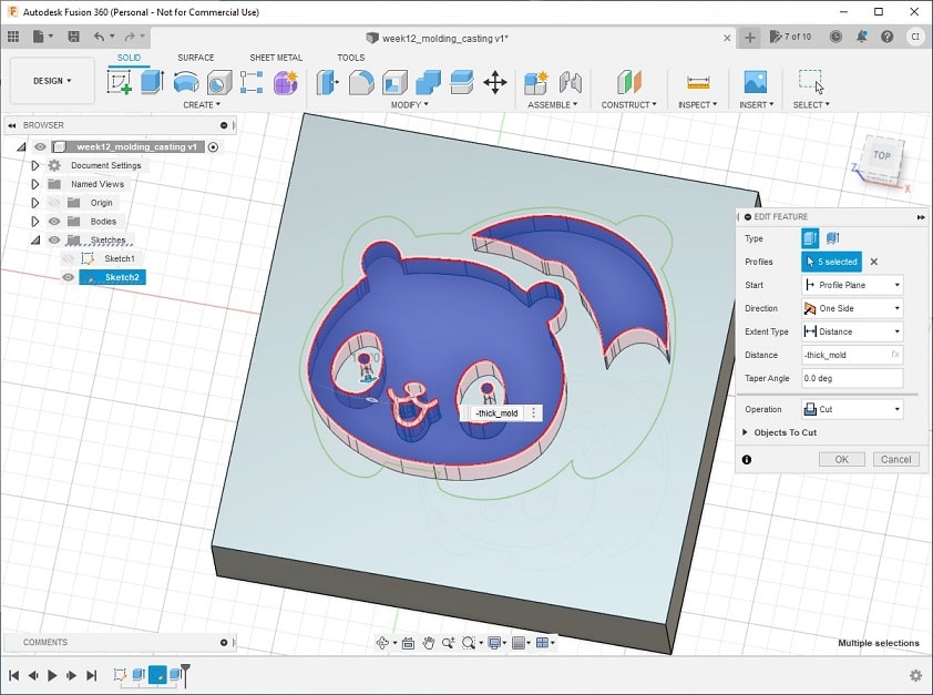
Create an extrude of the white part of the panda with the depth of thick_mold (first layer).
-
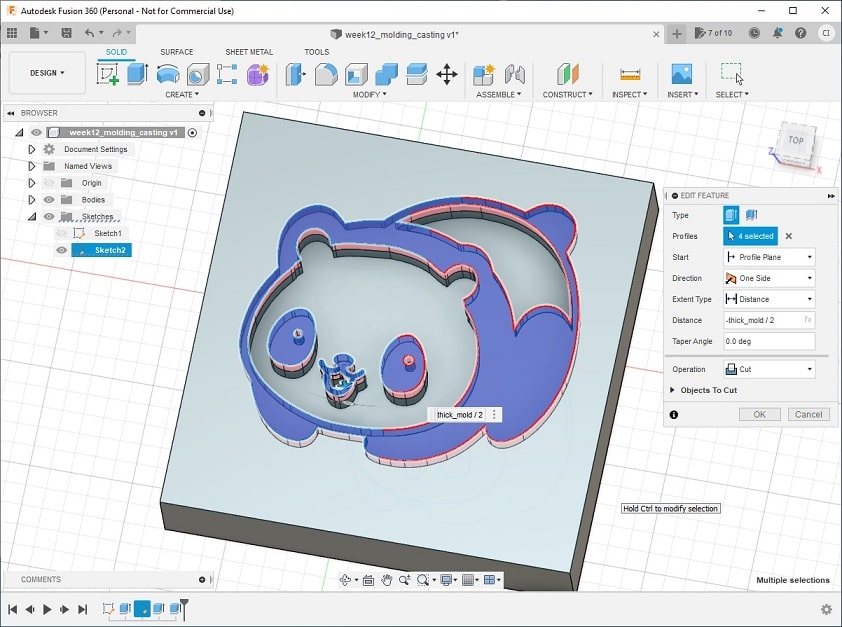
Create another extrude, now of the black part of the panda with the depth of thick_mold/2 (second layer).
Download the STL file (for fusion) of the generated drawing.
Preparing for milling
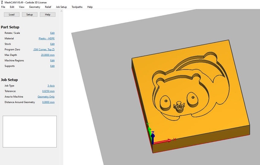
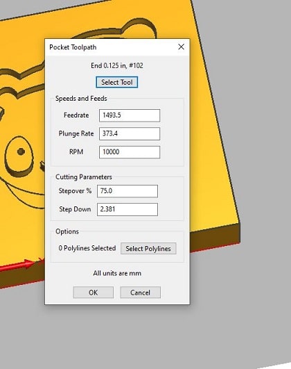
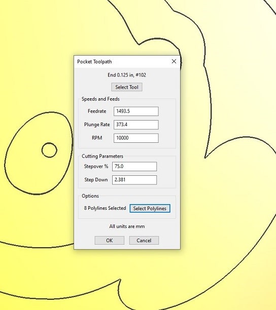
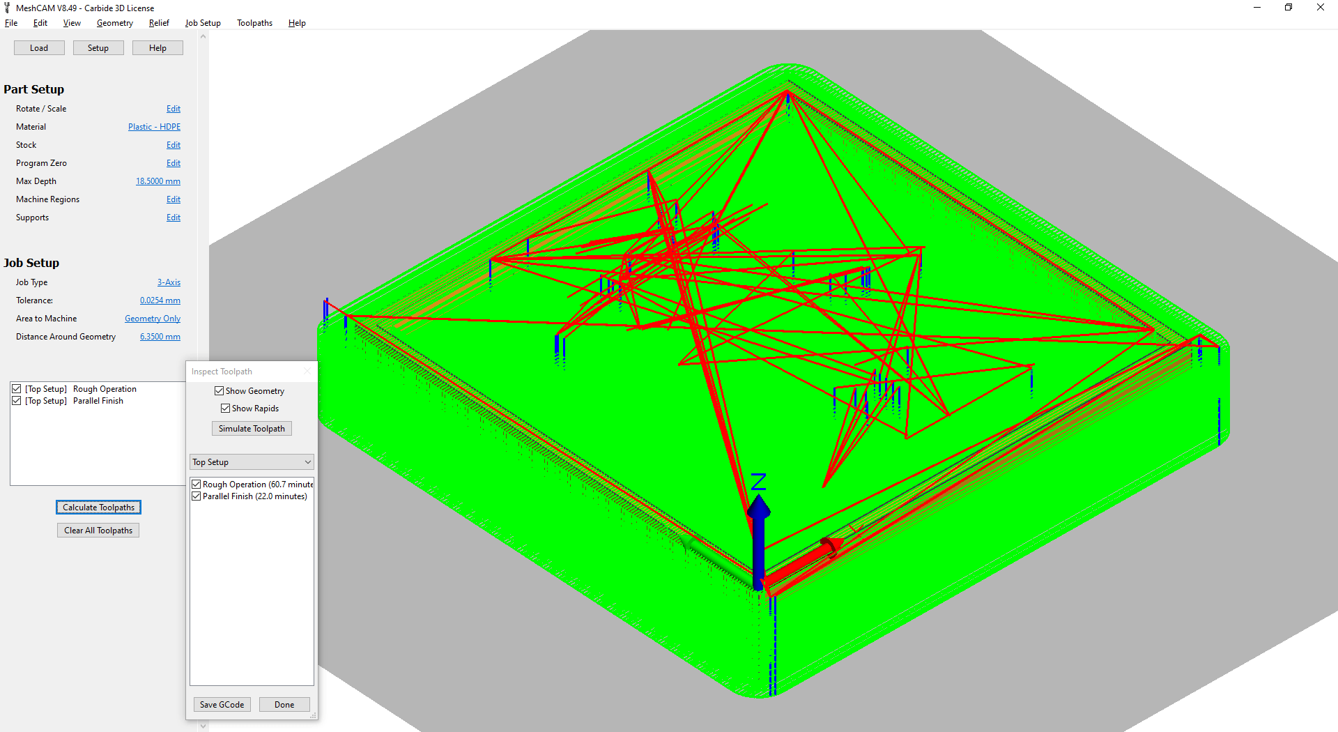
The generated file from the drawing, it was imported in the software MeshCAM, used to create the file with the paths that will be send to the milling machine. The parameters used is shown in the images. I have used the milling machine Nomad 883.
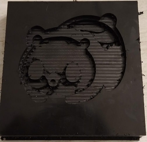
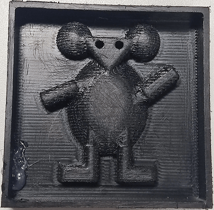
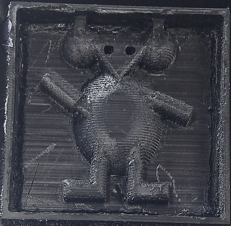
The resulted mold for the casting has some grooves because of the needle used to mill it. To fix this, I should use a different needle to make the mold more smooth. However, to save time I decided to use the mold with the grooves to make the casting.
Casting
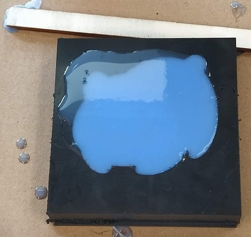
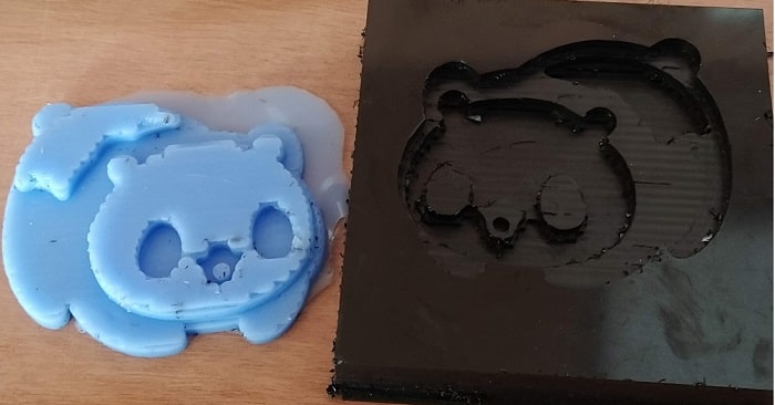
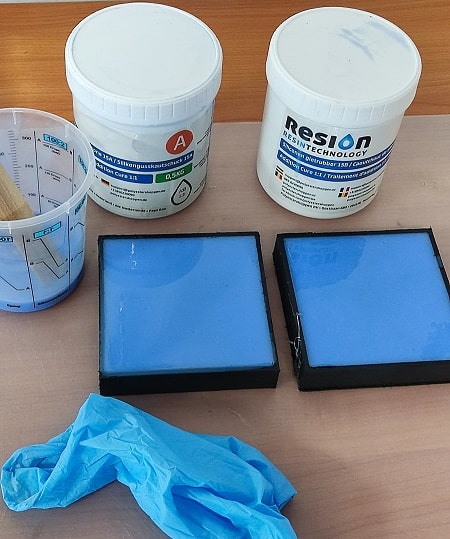
The resulted mold from the milling machine can be used to casting the object using different materials. For testing it, I have used a blue silicone that is a flexible material. The material is compoud by two fluids that once mixed, became the silicone. They were mixed in the proportion of 50-50 regarding their volume. The silicone has a ratio of 100-60. When the silicon was hard, i could remove it from the mold and the shape of the panda can be seen.
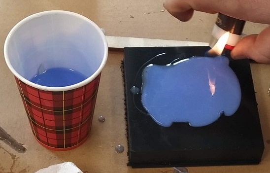
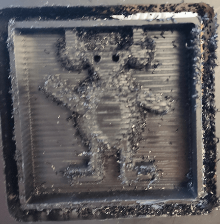
Burning to remove the bubbles from the casting.
Molding/Casting Two - Mouse
This shape explore molding and casting objects with round sides. It shows how the mill machine should be calibrate in order to mill the part that will make de molding rounded. I first tried to reuse the same image from the shape one, to make a panda that could be used as a toy. However, the drawing of the panda was not straightforward to make the round sides. I even tried to remake the entire drawing of the panda, but that task was not enabling Fusion to create the round sides well. I decided to make a different shape. I found the picture bellow and the result of it on Fusion enabled to make round sides that was required for this assignment. I used this image as inspiration to make the mold.

Design
The steps taken to make de 3D mold to be milled was a bit similar to the previous one, differing some steps that was specific for the round sides.
-
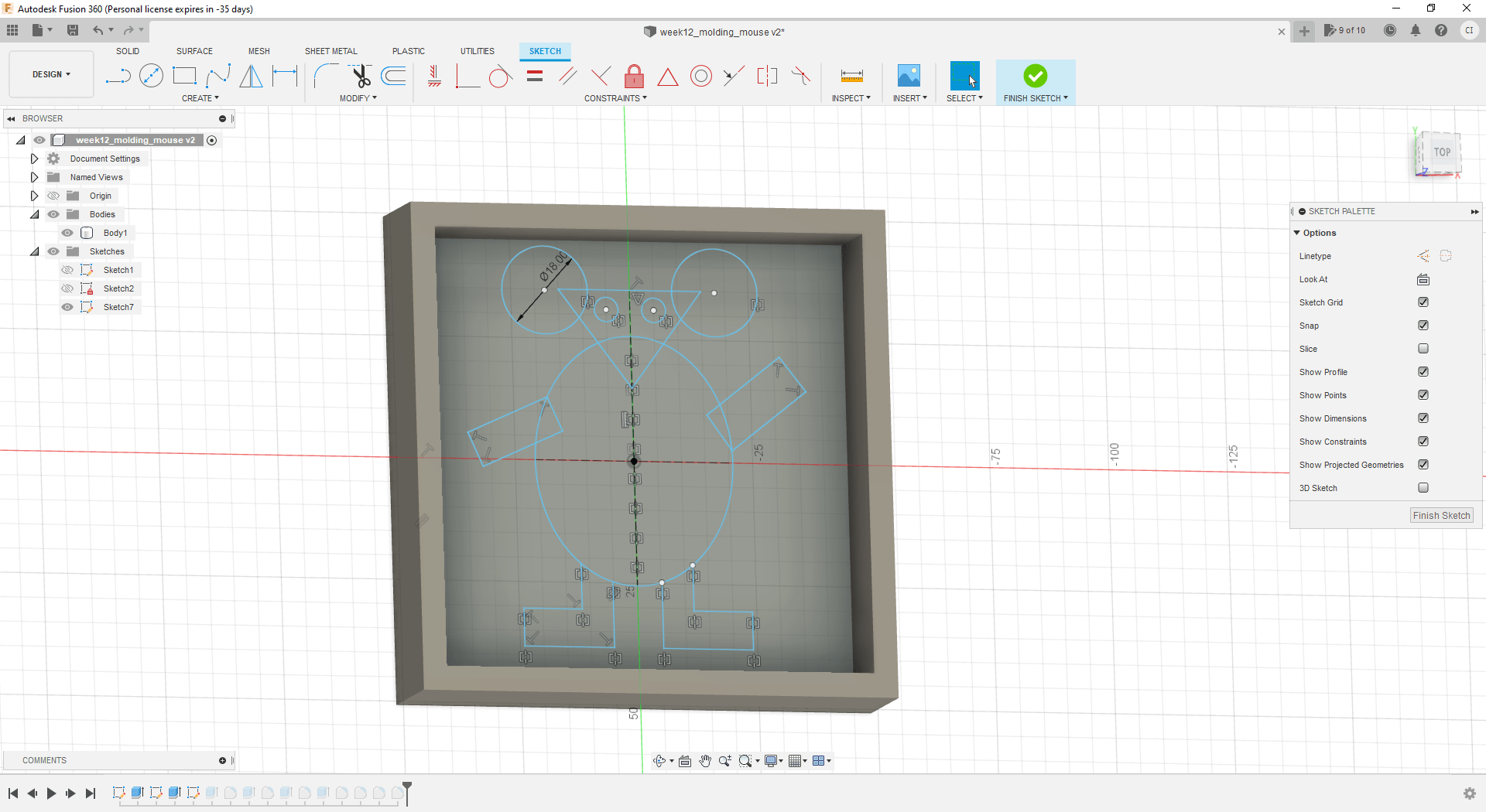
The image example was used in this part of the assingent was drawn at Fusion using the commands to draw shapes and lines.
-
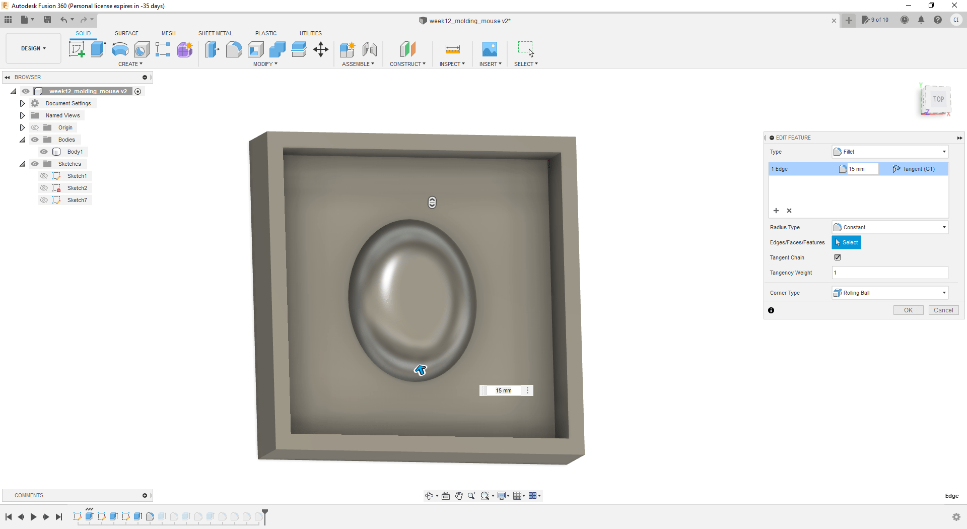
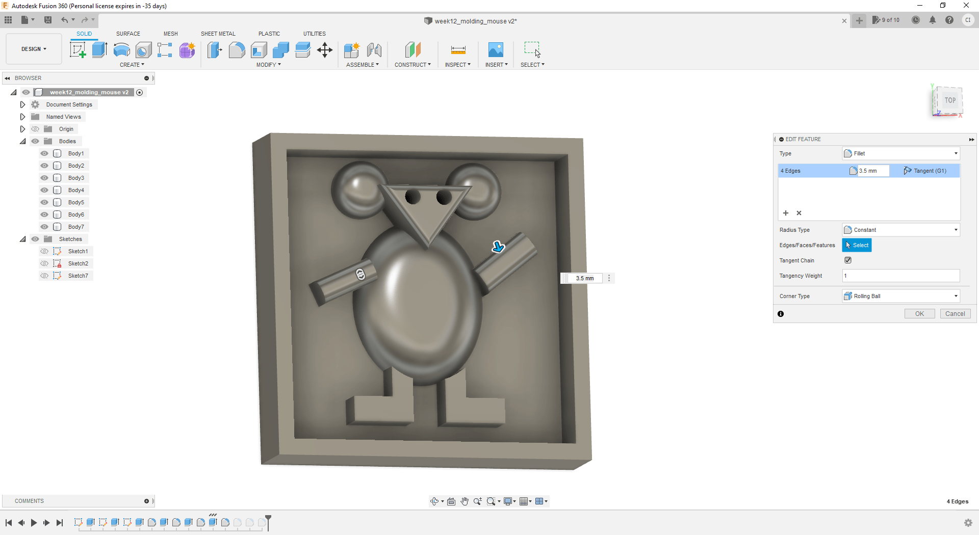
Extruding the middle of the mouse and making it round. After extruding the shape it was used the command Fillet to make the middle rounded.
-
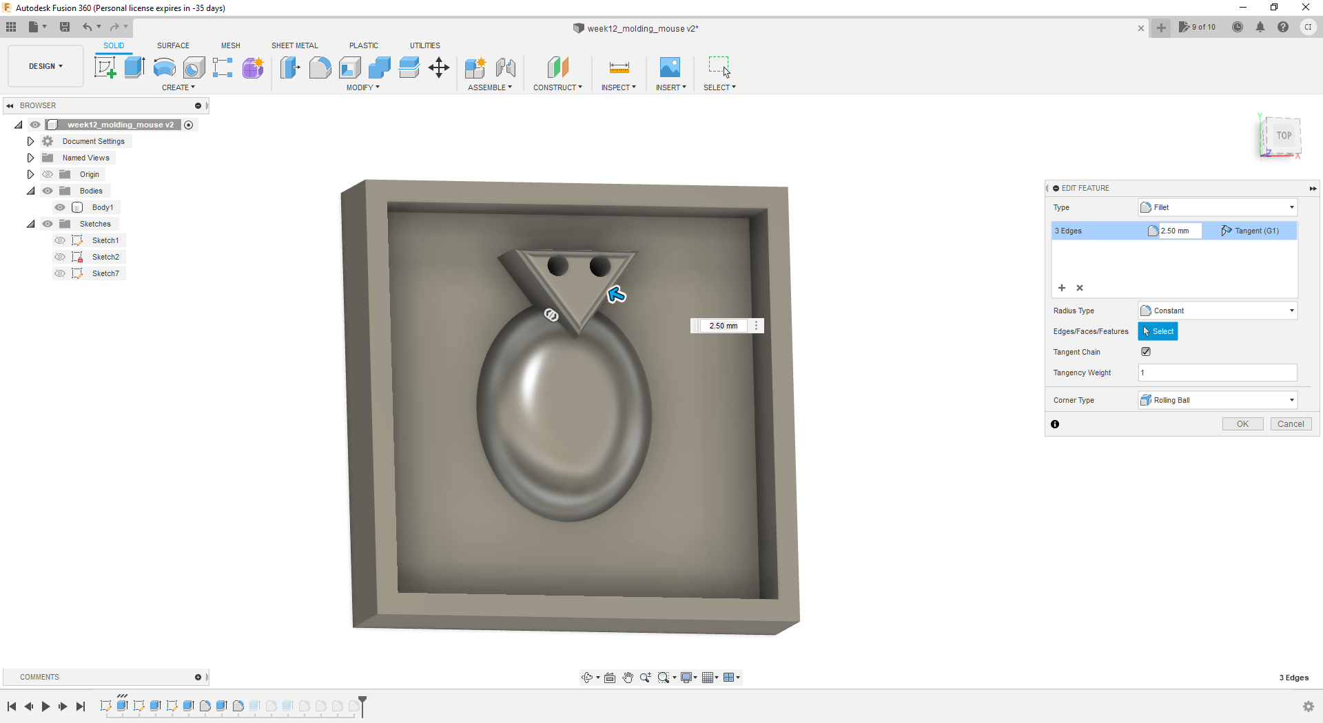
The same was done for the face, ears, arms, and legs of the mouse. The length of the Fillet was adjusted to the max value that Fusion could accept to make the edges rounded.

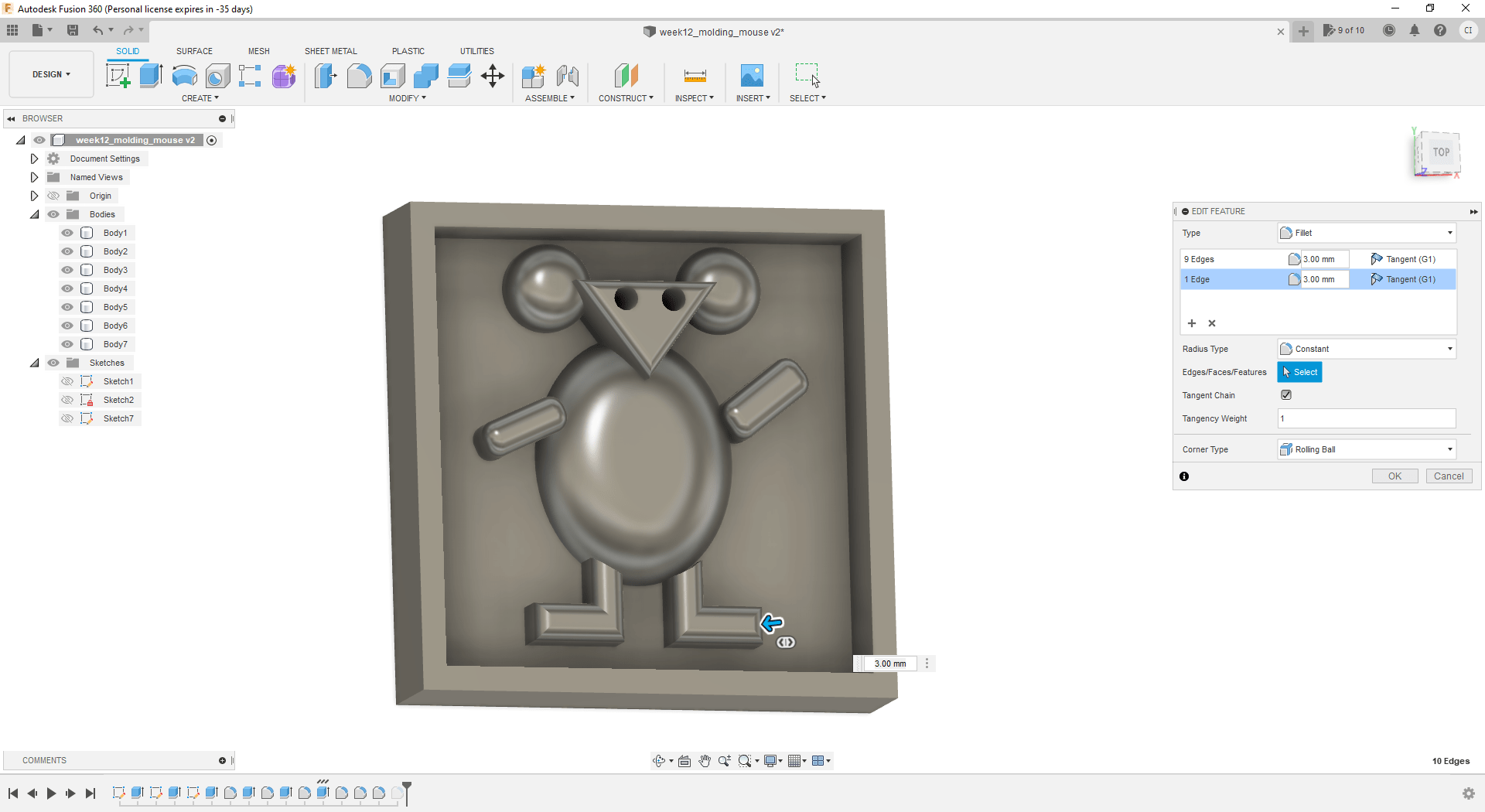

-
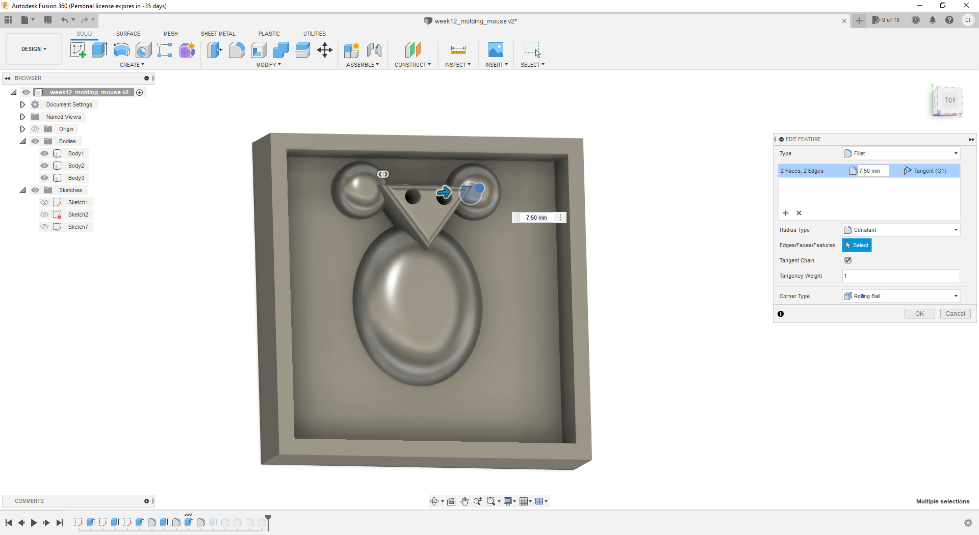
It was necessary to connect the arms and legs to the belly of the mouse. Otherwise the mill machine was not going to make the shape well as there was some very small edges between the arms/legs and the belly.
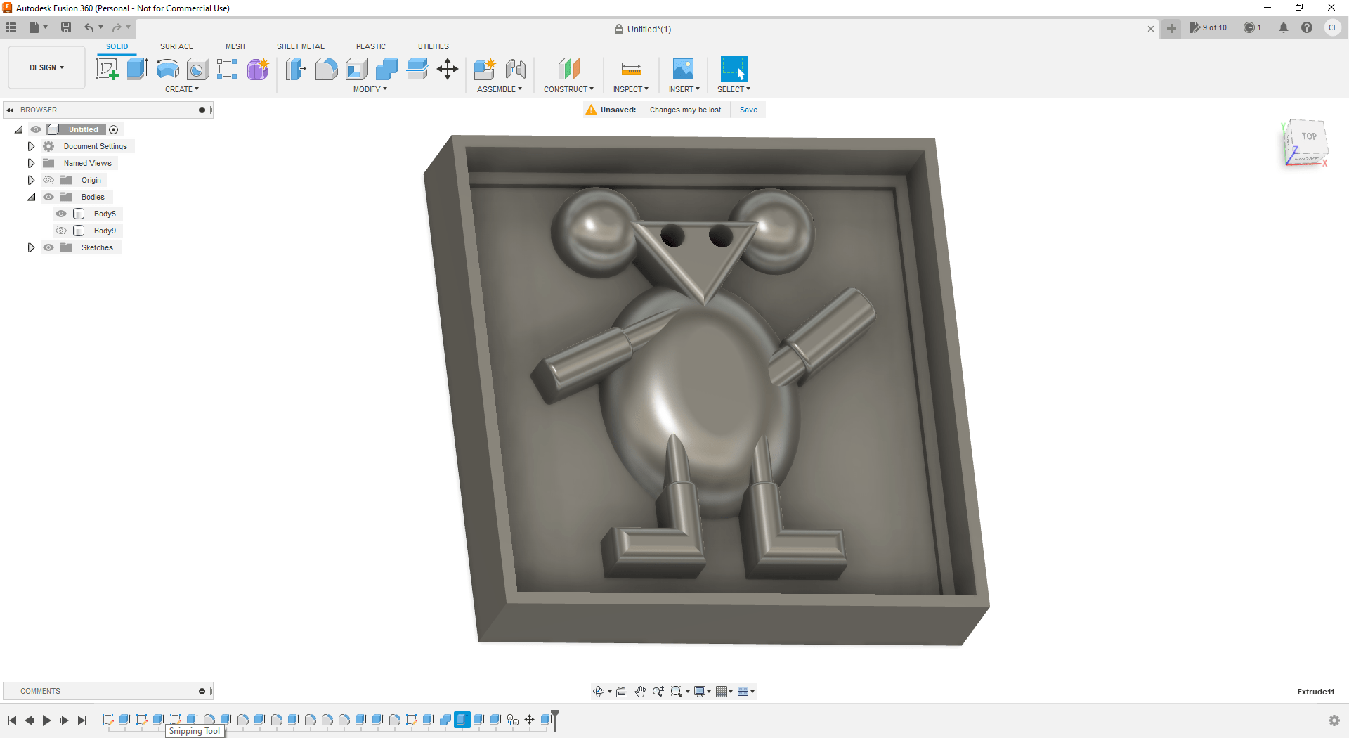
-
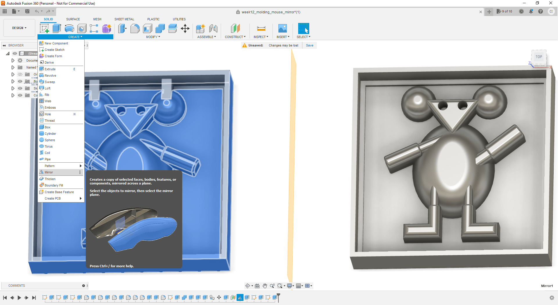
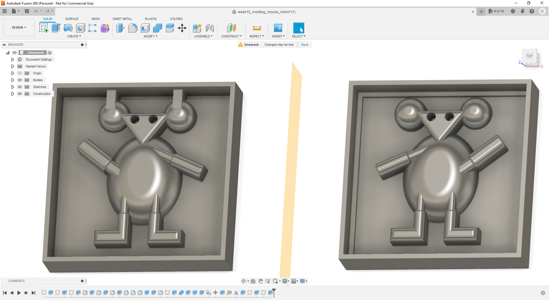
The final shape was duplicated in order to make the second part of the molding that will be used to make the 3D object. However this was not correct, because duplicating the body on Fusion would not create the mirror mold to make the 3D object.
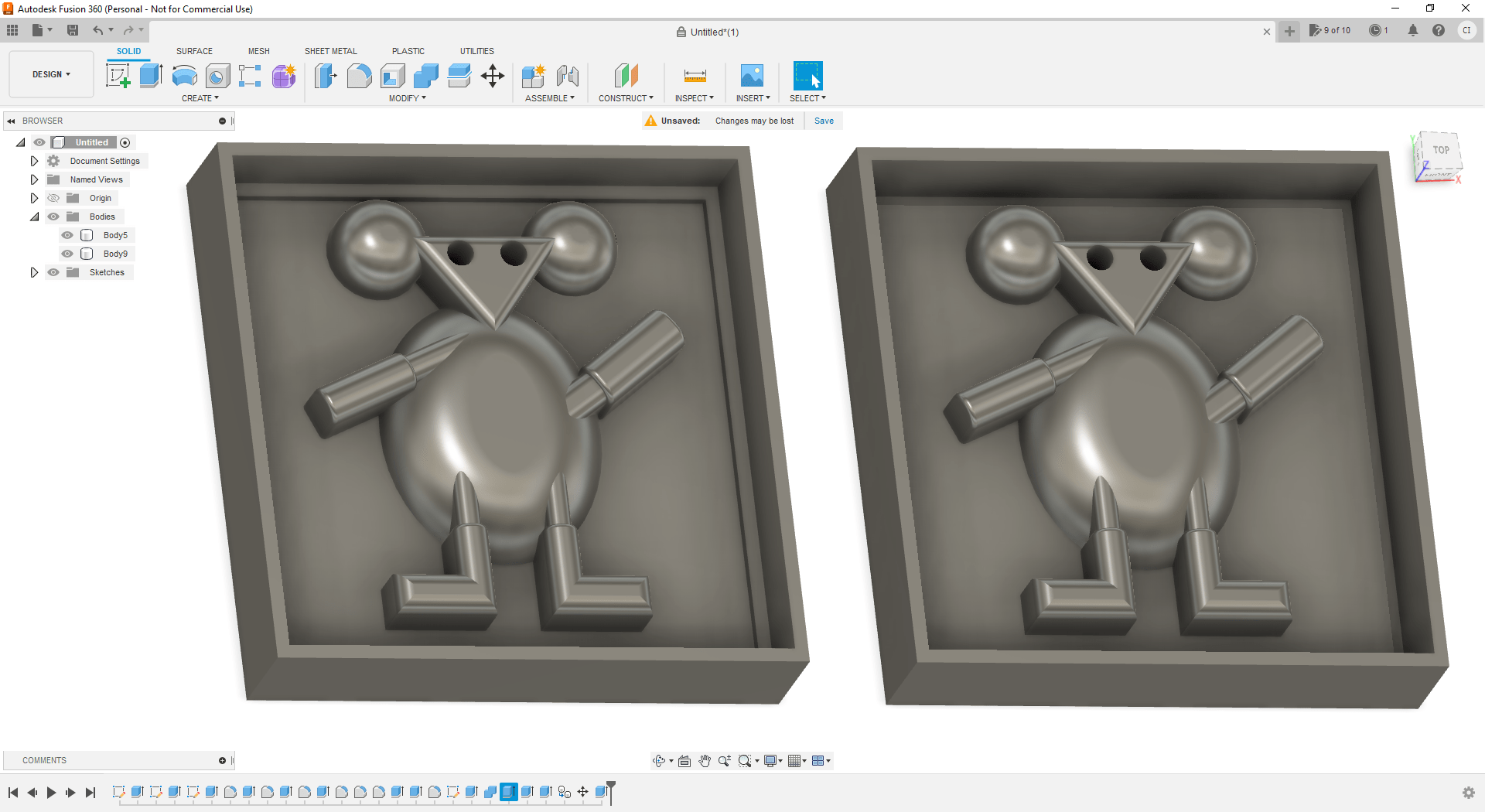
-
In order to make a mirror of the body, we added a plane in the Fusion design.
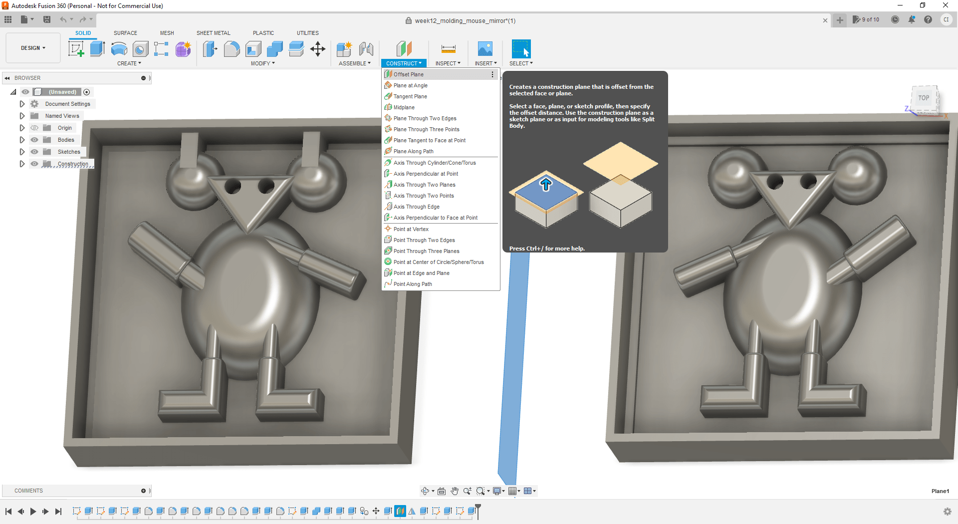
-
The entire body object on Fusion was duplicated using the added plane.
- It was make the complement of the edges of the mold to fit the first part together with the second part.
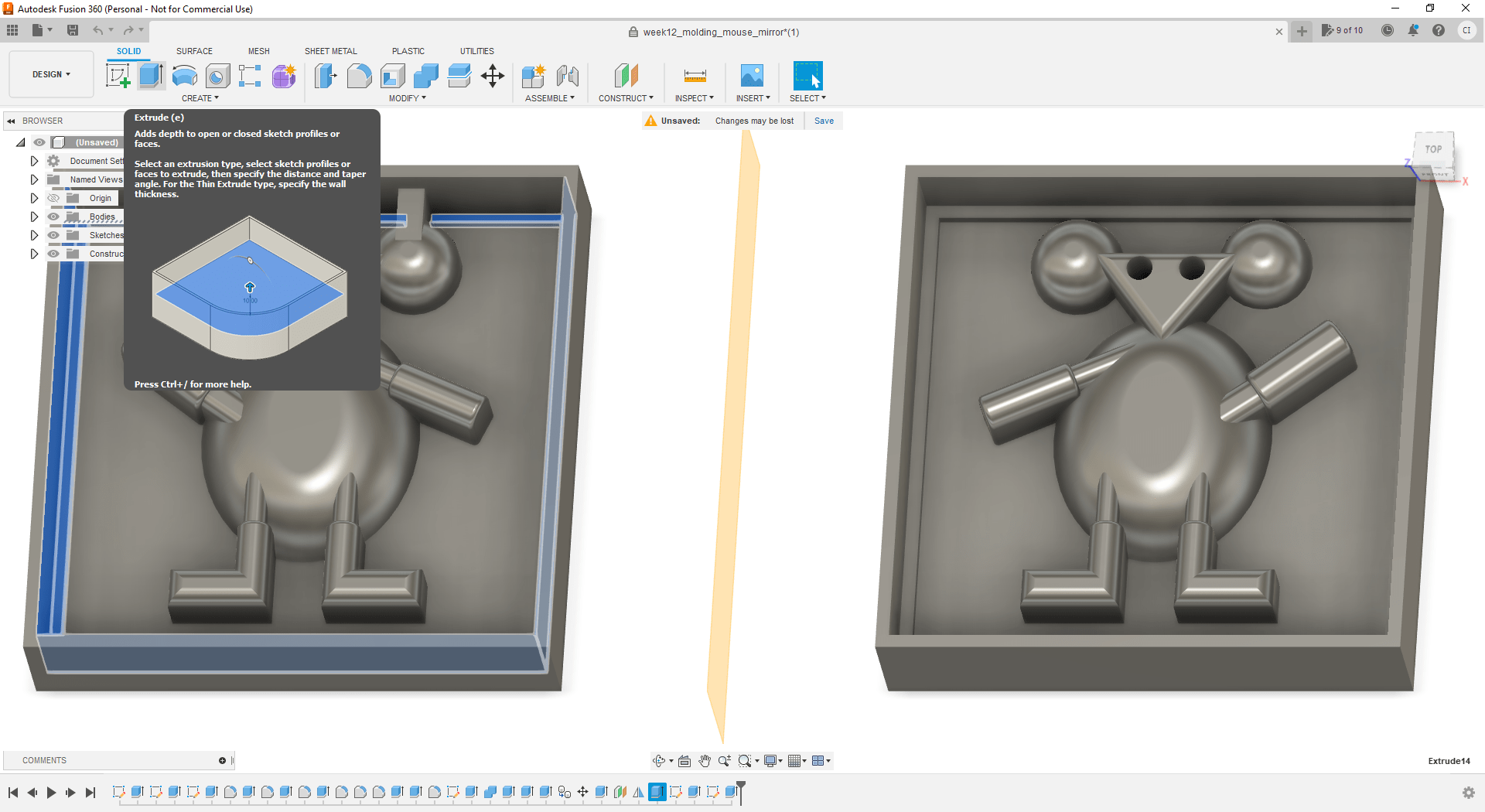
- I decided to add a hole on the top of the mold to enable adding the material that we will use in the last step (casting).
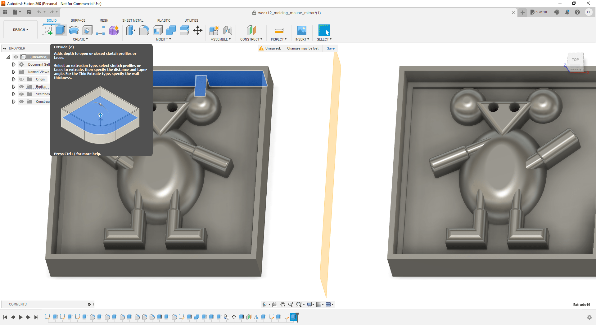
- Result of the design of the molding of this part of the assingment.
Download the F3D file (for fusion) of the generated design.
Milling
Preparation of the Fusion design to mill the mold. It was used the same software MeshCAM.
-
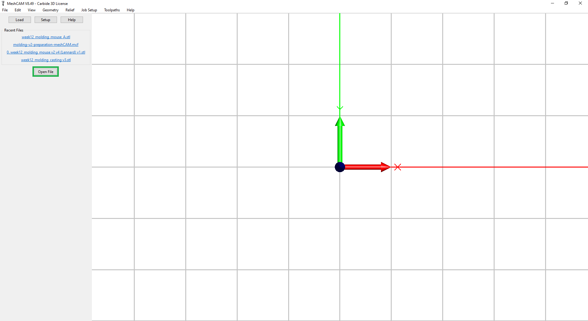
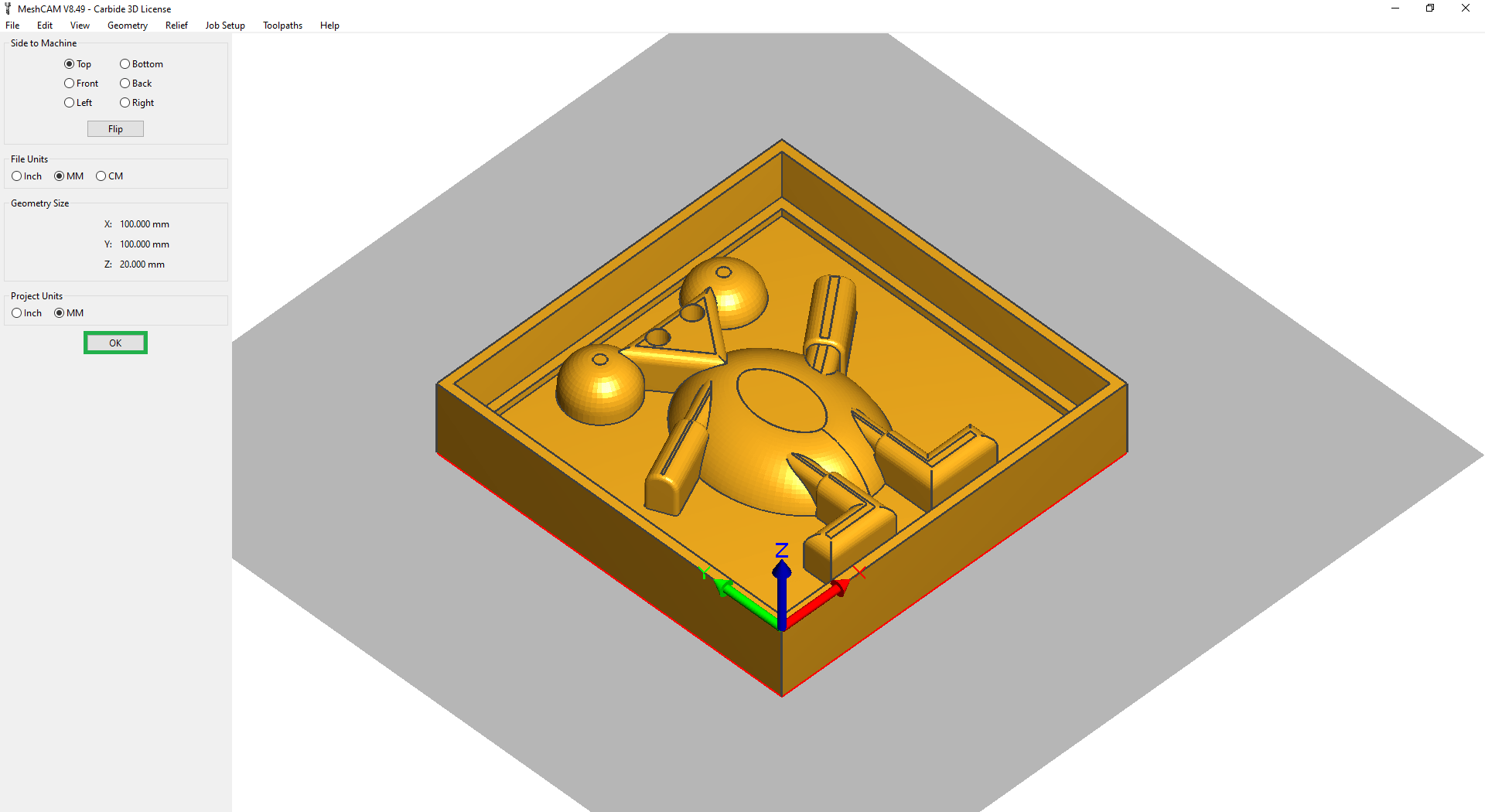
Imported generated STL file from fusion.
-
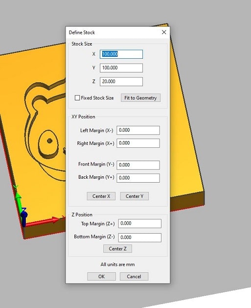
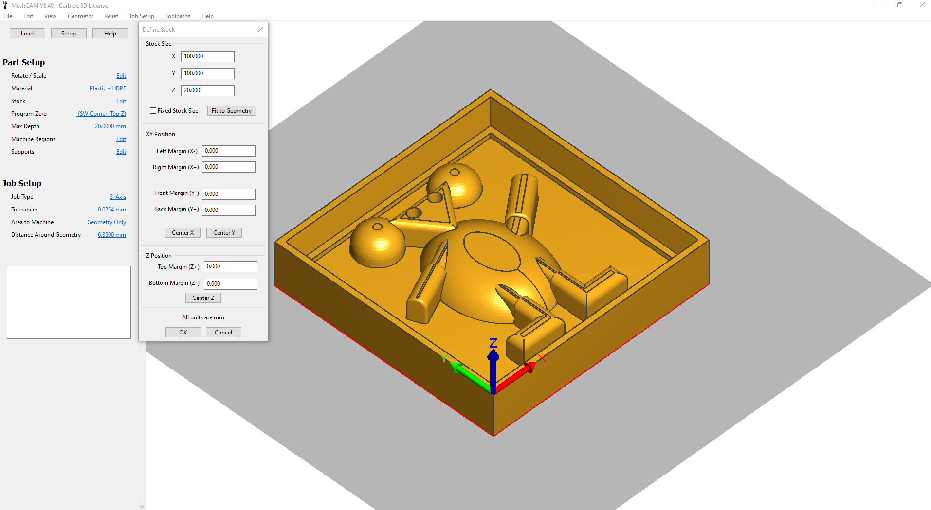
Definition of parameters of the mill machine. It was defined the length, height, and depth of the material that will be used to mill the mold (section Stock Size).
-
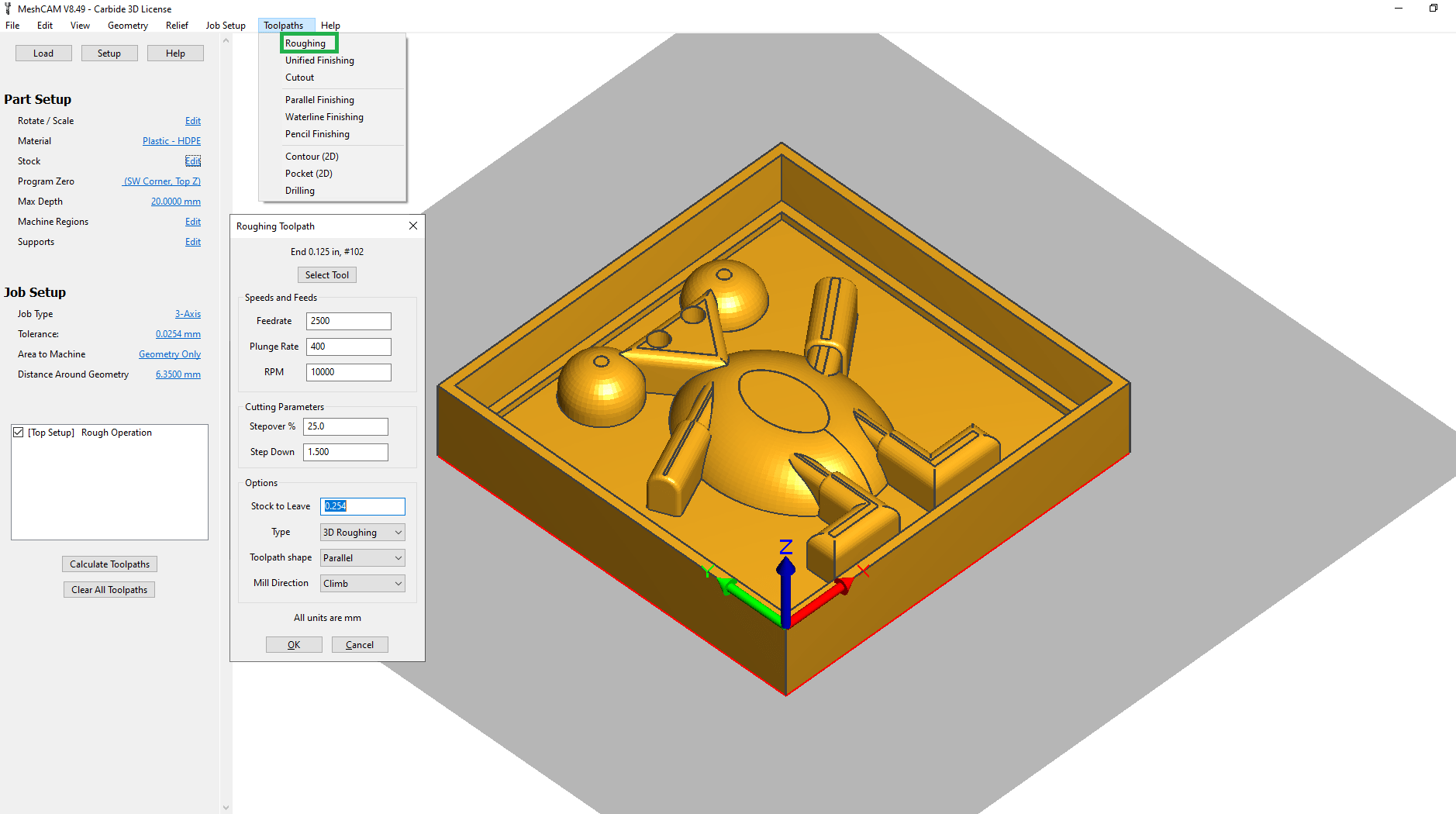
Added a Roughing toolpath that will mill the most of the mold. Selected the correct parameters according to the mill machine that will be used.
-
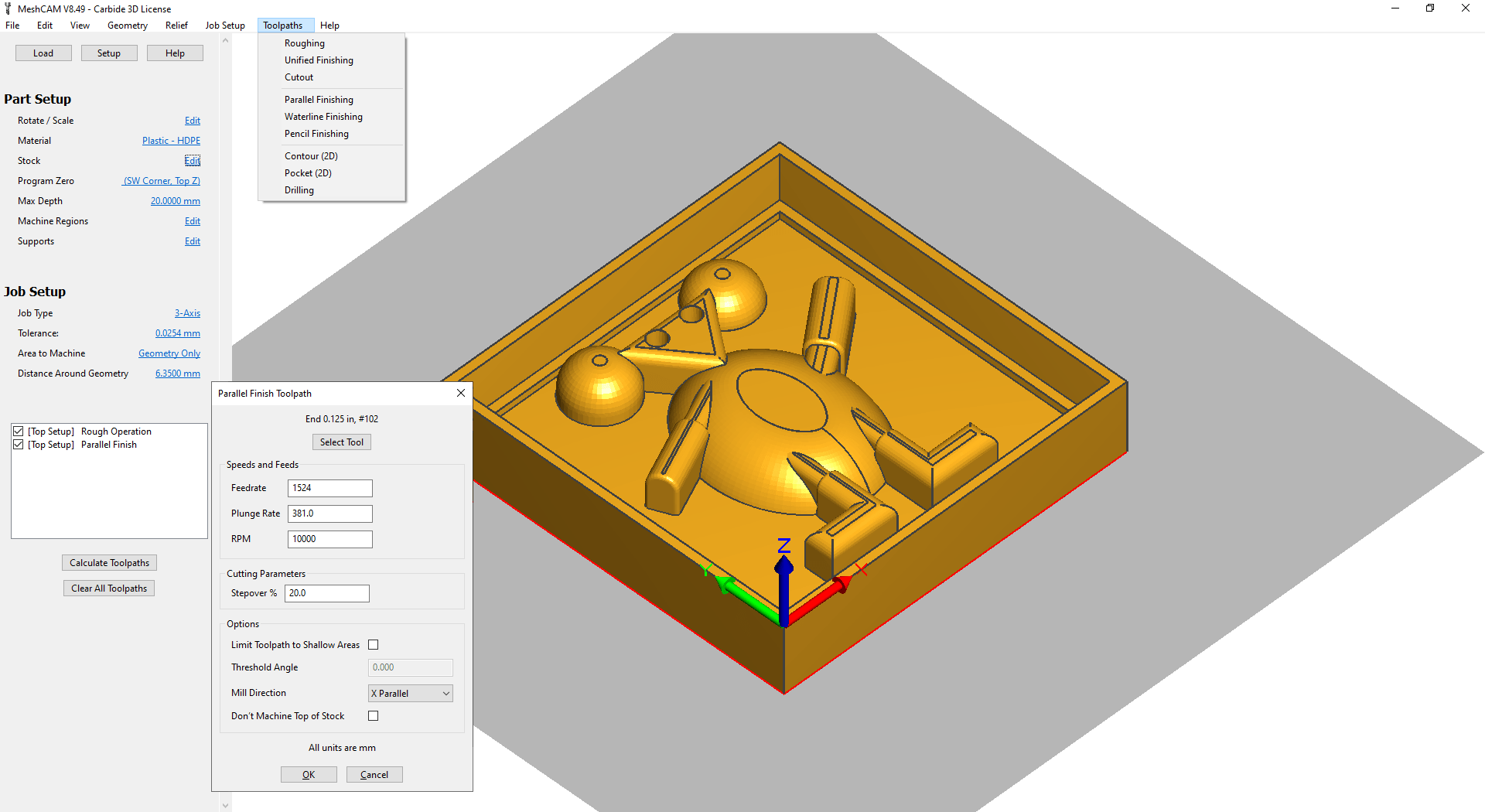
Added a Parallel Finishing toolpath, to make the edges more smooth and avoid too much lines in the final mold. Otherwise the 3D object will not have a good round shape.
-
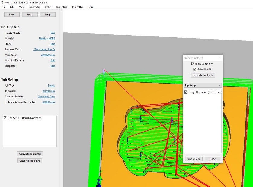
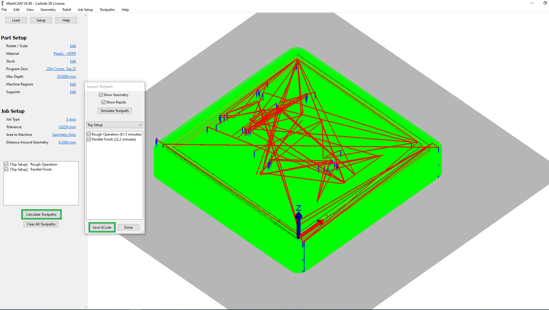
Calculated the Toolpaths and generated the GCode for both parts of the mold
-
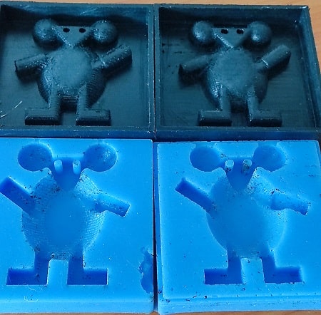
Part A
-
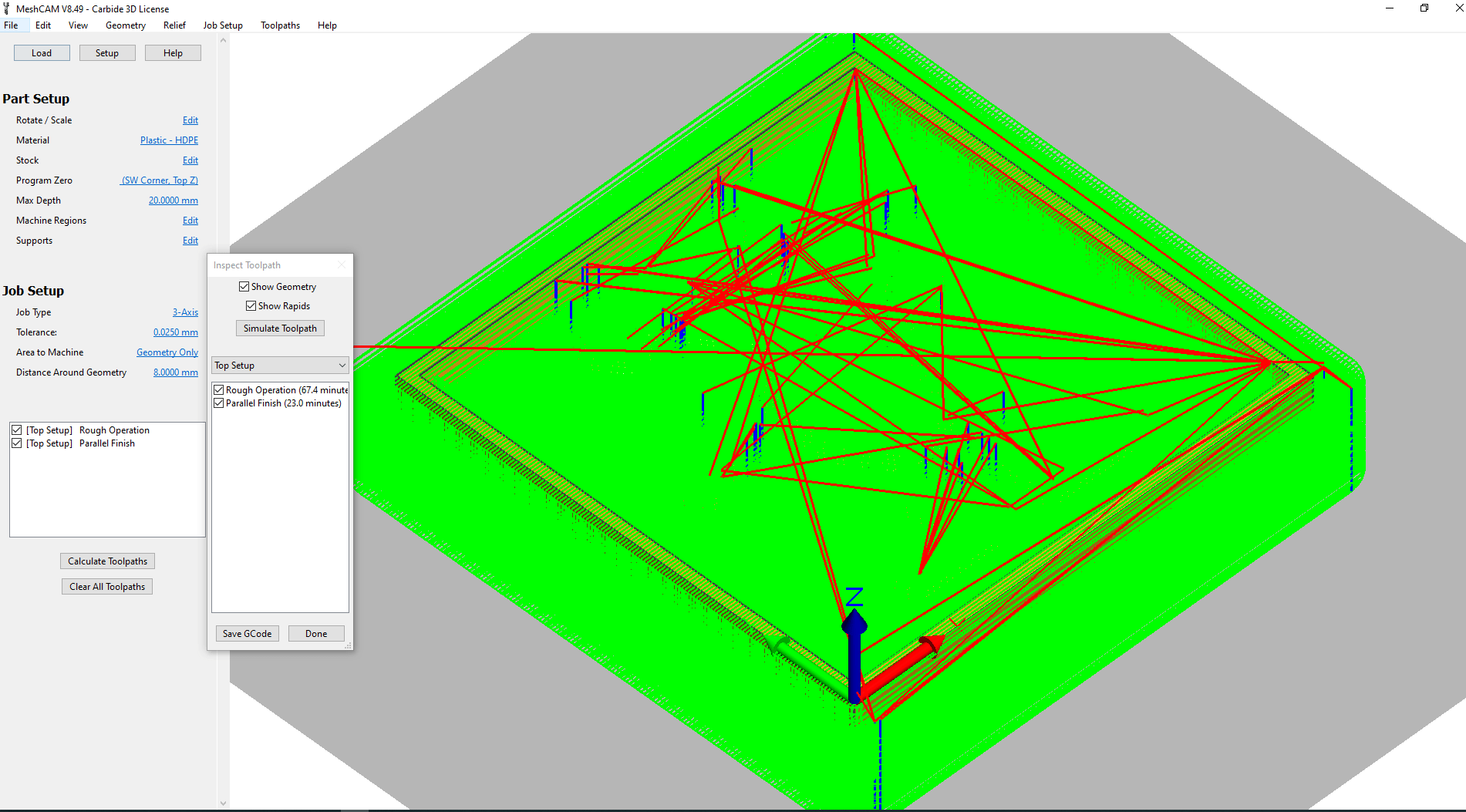
Part B
-
-
The result of part A was very good after some cleanup. Even using the toolpath to finish the mold it was necessary to make some manual cleaning.
-
However, the result of part B was not good. The mold moved during the milling process and as consequency the drill make a hole in the bottom-left edge. I have tried to add some glue, but the result was not very good. This happened when I tried to mill the wrong part B.
-
After redesigning the part B (mirroring the part A instead of copying), it happened the same problem mentioned in the previous step. The mold moved during the milling process.
-
I fixed that by changing the property Max Depth in MashCAM.
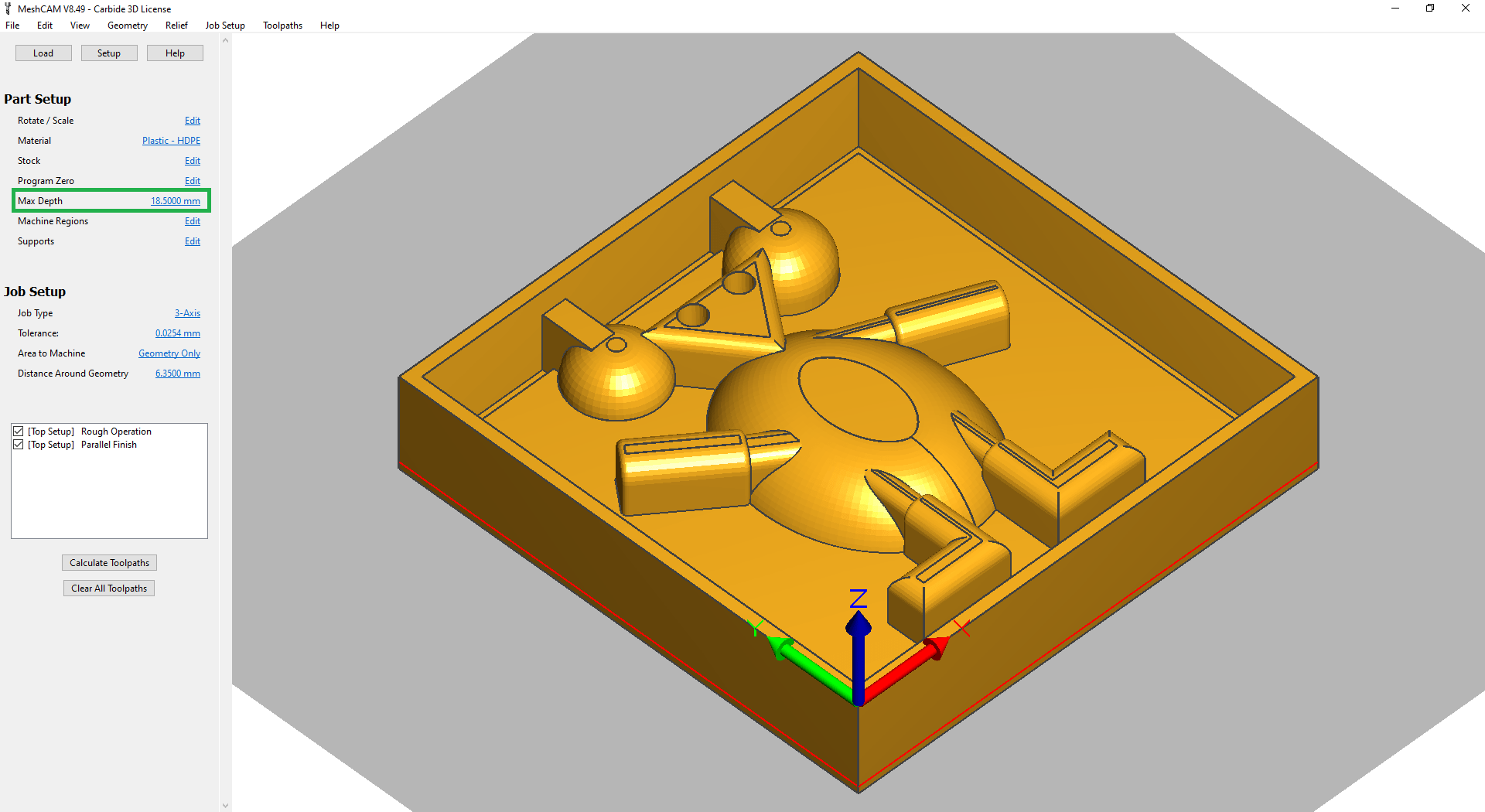
-
Then I regenerate the GCode of the part B of the mold.
-
The result was good and the mold did not moved during the mill process. However, the edges that would make the part B fit the part A was not milled. Perhaps I should have used a different Max Depth in the previous step 9. I have tried to make the edges manually, but the result was not very good because I choose the wrong size of the drill.
-
Even not making the edges, I will use a flexible material to make the mold, so I continued using the generated molds part A and B from this assignment.
Download
Mold A.
Download the STL file from mold A.
Download the MCF file (for MeshCam) from mold A.
Mold B.
Download the STL file from mold B mirrored.
Download the MCF file (for MeshCam) from mold B mirrored.
Molding
I have used the same silicon casting rubber (link) used in the first part of the assignent. The mix of both silicon is 50-50. They need to be very well mixed, to have a good molding. If we do not mix well, the mold can be stick and will not be good for casting the final object.
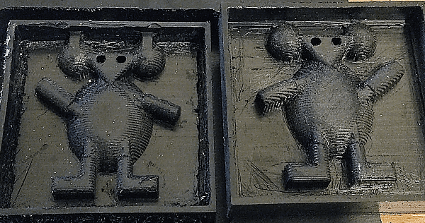
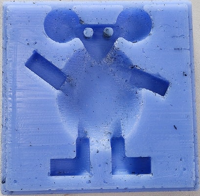
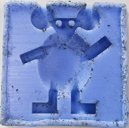
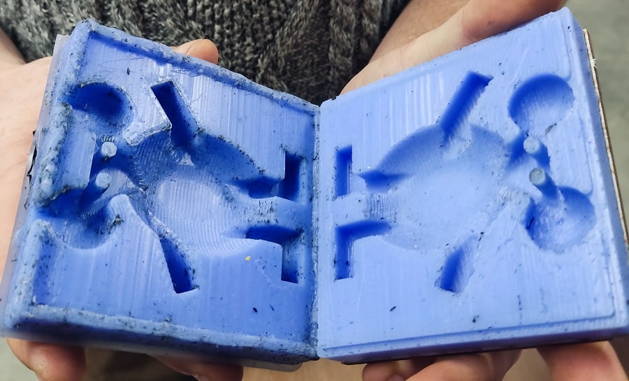
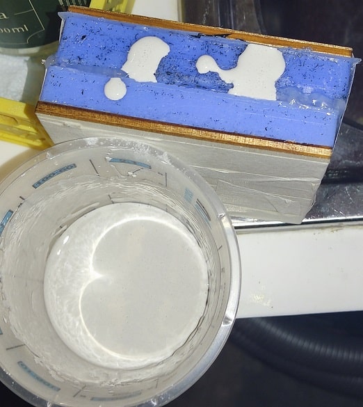
Part B (on the left) was not correct and I did it again fixing the error. Part A (on the right was correct and used in the next step).
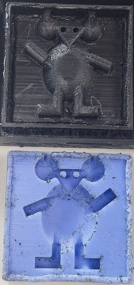
Molds used in the next step.
Casting
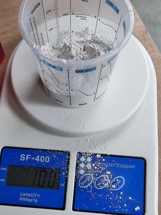
I have used ceramic powder to make the final object. The proportion they need to be mixed is 2.5 of powder
-
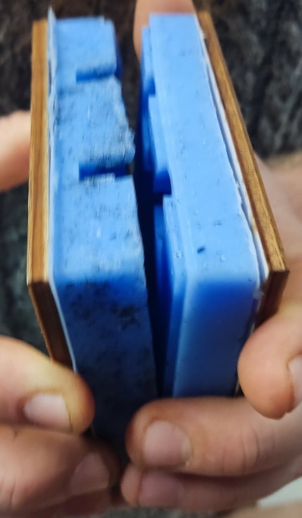
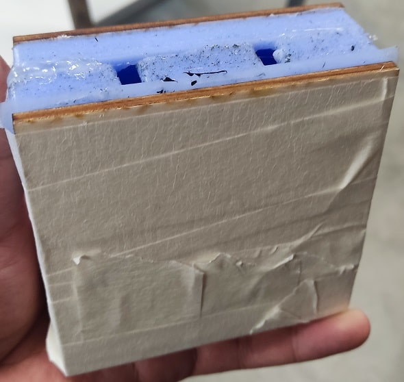
First I have added a wood in the back of both molds to make it strong when they are pressed together.
-
They were tapped together and used glu in the connection between both parts, to avoid any leaking between the molds, which would create unwanted lines in the final object.
-
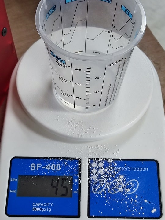
The proportion of powder and water to be mixed is 2.5 to 1, respectivelly.

-
I have used 100g of powder.
-
And 45g of water.
-
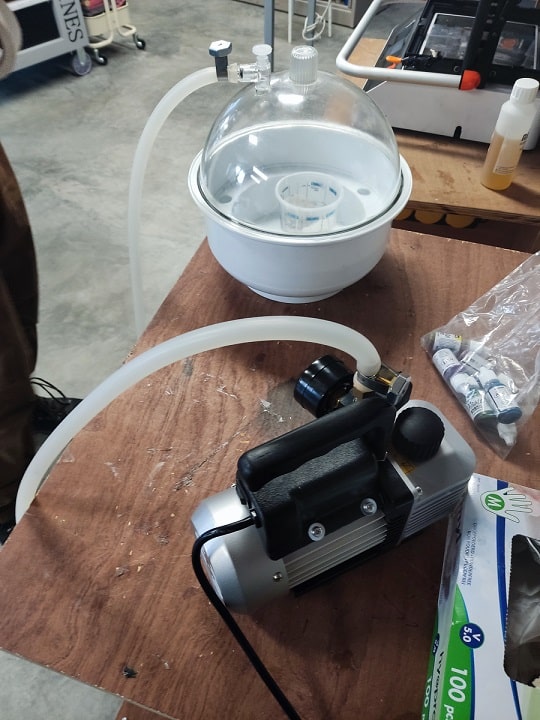
After miwing well the mixture of the powder and water, I have used this machine to remove the bubbles of it to avoid surface bubbles during the casting.
-
Pouring the mixture in the molding.
-
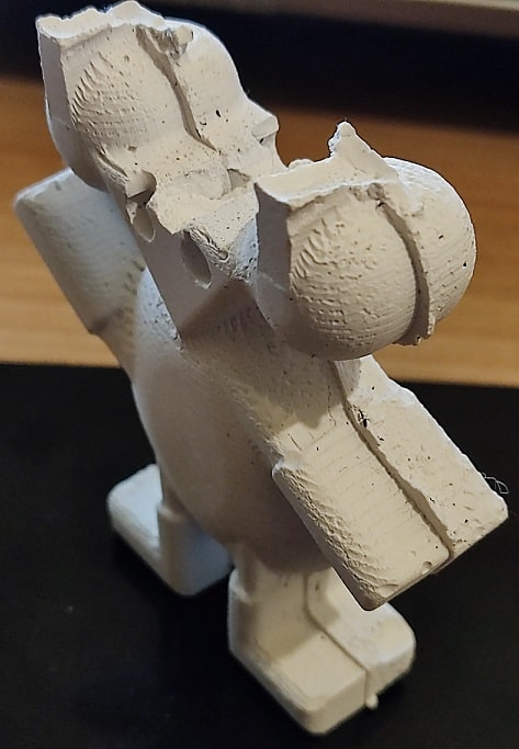
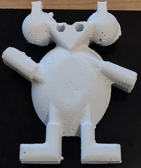
The resulted object was good, althought it could be better aligned to make a perfect match between both molds.
-
Also, the mixture in the top of the object was not well poured, maybe we should have shake a bit to spread better the material in the mold. In overall the result was good and show well the round sides of the designed objected.