3. Computer Aided design
Assignment
- model (raster, vector, 2D, 3D, render, animate, simulate, …) a possible final project, compress your images and videos, and post it on your class page
During the last week, I tried to learn the most possible about Markdown, MkDocs and the process used to update the documentation on GitLab and in addition a brainstorming was made to describe all the essential features that our project would have. Reuniting the ideas, it was possible for us to get the sketch shown below:
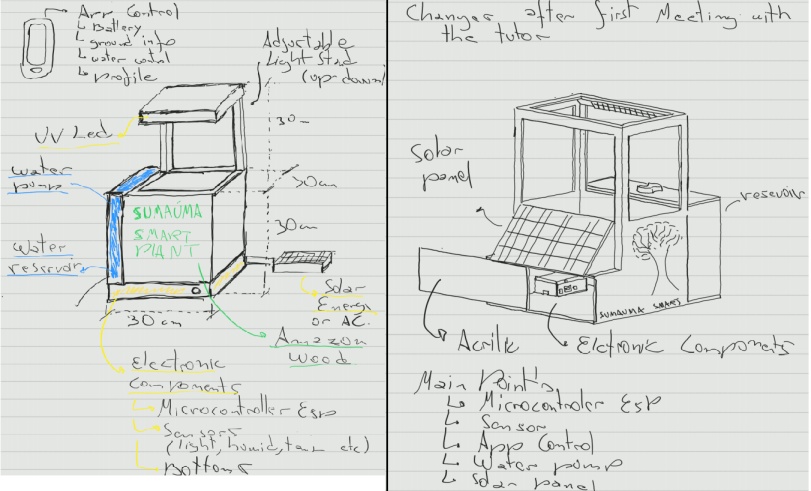
Image1 - Final Project Sketch
Note: This sketch was done in a 2D software name Samsung Note that I use in my Tablet.
I good tutorial of Samsung Note can be found in this video
Note 2: Fun fact, I stopped using conventional notebooks in 2008. It is possible to say that I am an early adopter of Digital notebooks. This technology improve a lot in the past few years.
In this new week I focused on the new assignment Computer Aided design (2D e 3D model)
Raster and Vector
I found a good definition about Raster and Vector in this Blog,
Raster Graphics
The particularity of a raster image is that it is made by little pieces, like a mosaic. These pieces are the pixels. The higher the resolution is, the bigger is the number of pixels for unitary area. For example: an image with 600x800px. Literally, it means that your image has 600 pixels vertically and 800 pixels horizontally. If you do not expand this image and look at your screen, your eyes will not notice the pixels. But if you print the image on a paper, like an A4 sheet, then you can see the mosaic.
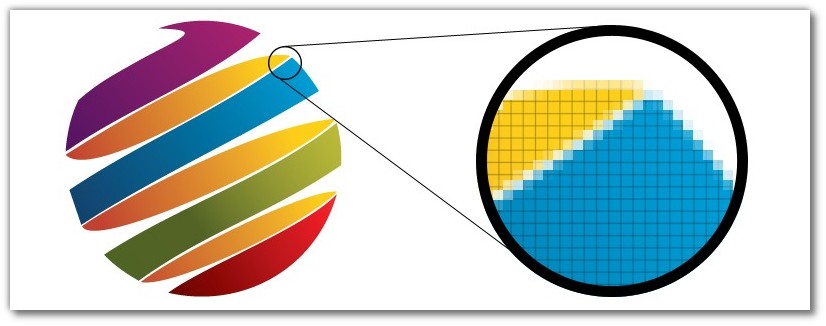
Image2 - Raster Graphic
In this site a good info about the definition of raster and vector.
Vector Graphics
Unlike the raster image, the vector is not composed by separated points – pixels. The logic in a vector image is a little bit different. In vector graphics, there are the control points, as they are called, and there are curves between them. The curvature inside of each curve is defined by a mathematical formula. That doesn’t mean the designer needs to be a mathematician and remember all the formulas for hyperboles and parables. This kind of work stays with the graphic program.

Image3 - Vector Graphic
SolidWorks
For the project modeling the software SolidWorks was used since I had a license of this software and have some practical experience with it.
About 10 year ago in college I used SolidWorks, o before I started using it again I decided to take a free online basic course in the render website. I used this course to familiarize myself with the commands again.
Note: Render has free and paid courses of SolidWorks, the course that I did was a free one named “SolidWorks 2014 Básico”
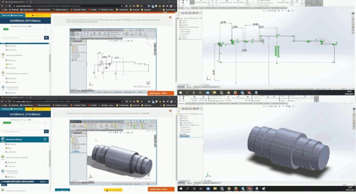
Image4 - Render SolidWorks Course
There is no mystery in understanding what SolidWorks really is. In short, it is a CAD (Computer-Aided Design) program which allows the object creation with 3D modeling. Its main goal is to help technical professionals, mainly from the industrial, medical, construction, transport, and production sectors in general. Through the software, you can:
- Make sketches;
- Build machines and observe its operation;
- Simulate movements and observe possible failures;
- Create project animations;
- Render jobs realistically, etc.
3D Modeling
With the project sketch in hands, it was possible to improve the initial idea using 3D modeling.
To demonstrate the step by step of a 3D model creation using the SolidWorks software, I will show some basic operations for a less complex section, like the project for the water tank. First, you must select the “Part” creation option, then select the “Sketch” tab and the “Sketch” option. In this moment, you can choose in which three-dimensional space plan you want to start to build your part.
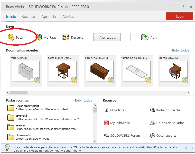
Image5 - Selecting "Part"
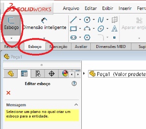
Image6 - Selecting "Sketch"
Choosing the upper plan, I’ll start the construction of the part. For that, still in the “Sketch” tab, first selected the rectangle construction tool. Then, designed an 300x100mm outer rectangle and an 290x90mm inner rectangle, assigning these measures through the “Smart Dimension” tool, as shown in the picture below.
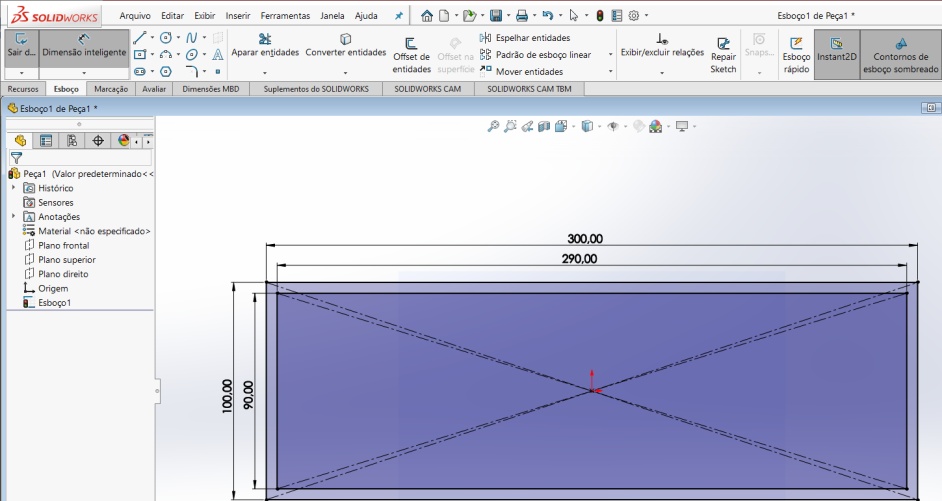
Image7 - Rectangle
After this, selected the “Features” tab and the “Extruded Boss/Base” option. Thus, just define the desired height for the extrusion, in this case 250mm.
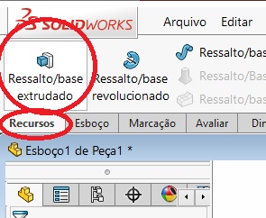
Image8 - Extruded Boss/Base
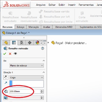
Image9 - Height
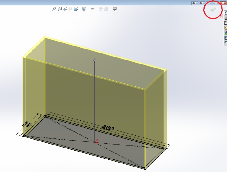
Image10 - Result
So, I obtained the following part, still without cover and without texture.
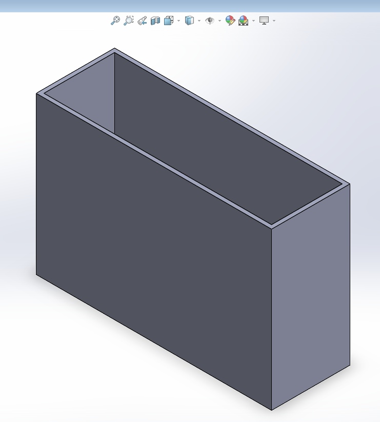
Image11 - Result2
It is very simple to add some appearance to a 3D object. In the toolbar above the part, select the “Edit Appearance” tool and many appearance options will appear. I choose the “Plastic” – “Transparent Plastic” – “Translucent Plastic” ones.
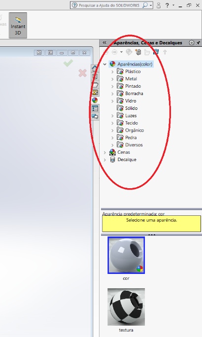
Image12 - Edit Appearance
And then, was obtained the following final 3D object.
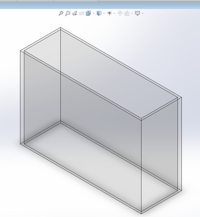
Image13 - Part with Transparent Plastic appearance
The same logic was used to build the other parts of the project.
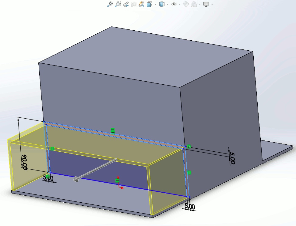
Image14 - Other parts of the project
Again we add some appearance to the 3D object In the toolbar above the part, select the “Edit Appearance” tool and many appearance options will appear. I choose to the body of the project “Organic” – “Wood” – “polished walnut 2d” ones.
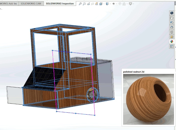
Image15 - Sketch with polished walnut 2d appearance
After that, all of them were grouped using the “Assembly” option, which puts all the project components together according to the designer’s interest, using basically two tools – “Insert Component” and “Position”. The “Insert Component” tool adds several parts of your interest in the same three-dimensional space, and the “Position” tool attaches these parts together through points, edges, planes etc. By that way, I obtained the following final model of our 3D project and a 2D model which shows the used measurements.
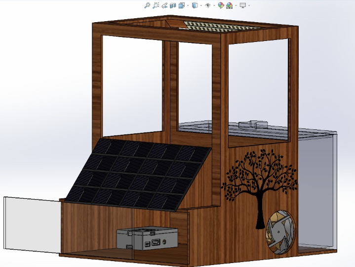
Image16 - Final 3D Model
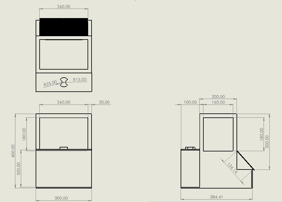
Image17 - 2D Model with measures
Video of the Project with SolidWorks
Note: The electronics components (raspberry case and Cooler) shown in the picture of the final 3D project were imported from the 3D model platform GrabCad. Below I small tutorial how to use GrabCad
2D Modeling
Another possible way to develop the project is starting with a 2D modeling and migrating the results to 3d Modeling. On SolidWorks, I searched for the option “Design” and created the first design area, then selected the paper format to be used. After that, I went to the sketch options tab, where there are several geometric parameters, selecting the best options and editing them according to our project. This way we obtained the isometric view of the project.
Image18 - Selecting Design
Image19 - Selecting Sketch
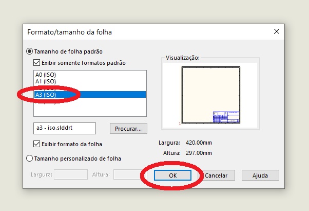
Image20 - Sheet size and shape
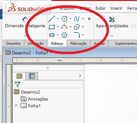
Image21 - Geometric parameters
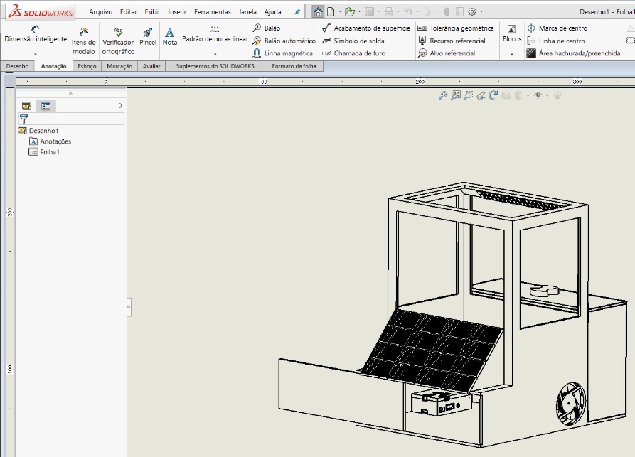
Image22 - 2D Sketch
Following the same logic, it was possible to sketch each one of the parts of the project in front, upper, side, and isometric views separately. Amongst them, these main parts are the Plant Vase/Component Compartment, the Water Tank, and the photovoltaic panels support.
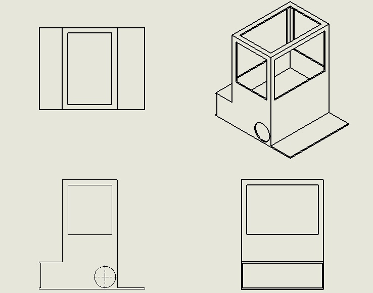
Image23 - Isometric View 1
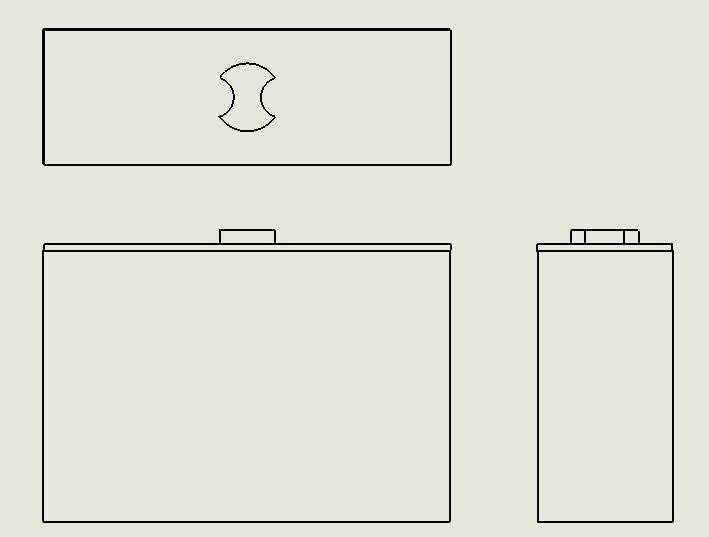
Image24 - Isometric View 2
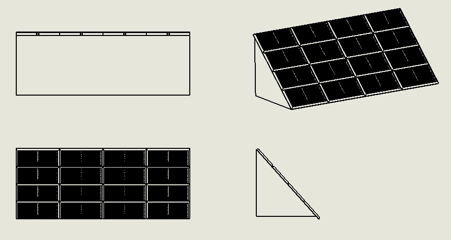
Image25 - Isometric View 3
Inkscape
The other 2D software that I tried to use was Inkscape a Free and open source vector graphics editor for GNU/Linux, Windows and MacOS X. My goal using this software was to vectorize the Sumaúma tree image of the project.
First I watched a nice YouTube tutorial by Ardente Designs
The first step was to open the image in the software then the following prompt appeared
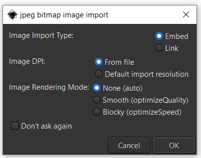
Image26 - Inkscape prompt
I used the default settings.
Second, I selected the image, then in the top of Inkscape toolbar, I clicked on Trace Bitmap, this will bring up a new window, as show in the picture Below. You can push the update bottom to preview the results
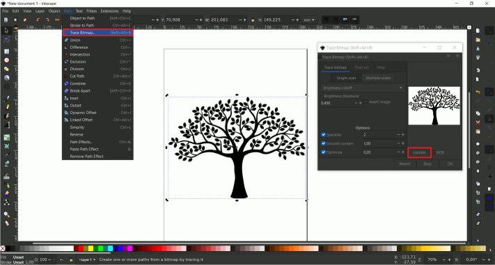
Image27 - Inkscape window interface
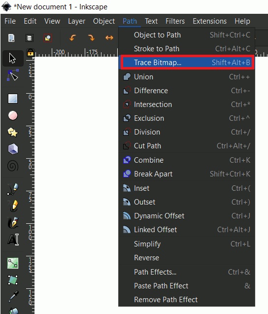
Image28 - Selecting Trace Bitmap
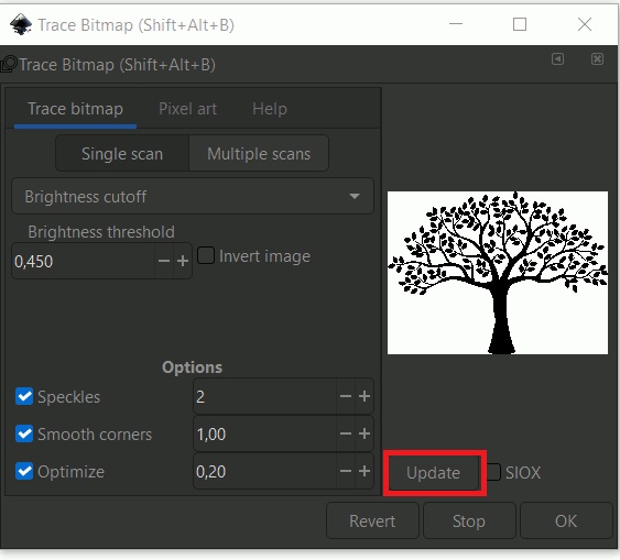
Image29 - Trace Bitmap window
Once you click OK in the Trace Bitmap window, Inkscape will take a few moments and vectorize your image.
GrabCad
In the GrabCad site in the search field show in the picture below you put the name of the Cad component that you want to use in your project.
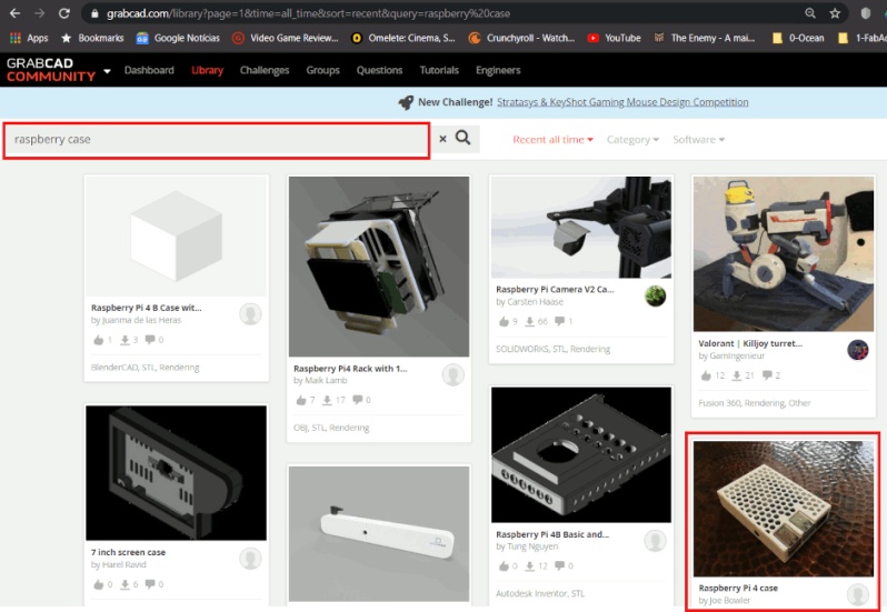
Image30 - GrabCad
Then you choose the CAD that you want and push the download button. As show below
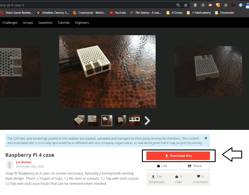
Image31 - Raspberry Pi 4 Case
Usually the download file will have a CAD files, some jpg and STL file.
We use in the project 2 GrabCad files:
Conclusions
3D data modeling for my final project
-
3D data - Final Project: the size of the CAD files in SolidWorks was around 50mb, so because of that I prefer to put all the files in my Dropbox repository
-
2D data- Sumaúma tree SVG and PDF files in my Dropbox repository
MEMO: What I wanted to learn more
- Using spiral management I will try to use others software to model my final Project as Freecad, Eagle and for personal interest ZBrush